Sign In
Upload
Manuals
Brands
Tektronix Manuals
Inverter
B020000
Tektronix B020000 Manuals
Manuals and User Guides for Tektronix B020000. We have
5
Tektronix B020000 manuals available for free PDF download: Service Manual, Instruction Manual, User Manual
Tektronix B020000 Service Manual (350 pages)
Waveform/Vector Monitors
Brand:
Tektronix
| Category:
Monitor
| Size: 5 MB
Table of Contents
Table of Contents
6
Table 1- 1: Waveform Vertical Deflection
21
Table 1- 2: External Reference
24
Table 1- 3: Waveform Horizontal Deflection
24
Table 1- 4: Measurement Cursors
25
Table 1- 6: Calibrator
26
Table 1- 7: Vector Mode
26
Table 1- 8: Audio Mode
27
Table 1- 9: Time Code
28
Table 1- 10: SCH Phase Mode (1750 Series and 1760 Option SC Only)
28
Table 1- 11: Component Vector Mode (1760 Series Only)
30
Table 1- 12: Lightning Mode (1760 Series Only)
30
Table 1- 13: Bowtie Mode (1760 Series Only)
31
Table 1- 14: Transcoded GBR Outputs
31
Table 1- 15: CRT Display
32
Table 1- 16: Power Source
32
Table 1- 17: Environmental Characteristics
32
Table 1- 18: Physical Characteristics
33
Table 1- 19: Certifications and Compliances
34
Figure 2- 1: Dimensions of the 1700F00 Plain Cabinet
38
Figure 2- 2: 1700F02 Portable Cabinet
39
Figure 2- 3: Rear View Showing the Securing Screws
40
Figure 2- 4: the WFM7F05 Side-By-Side Rack Adapter
41
Figure 2- 5: a WFM7F05 with a Blank Front Panel (1700F06)
41
Figure 2- 6: WFM7F05 Rack Mount Cabinet with a 1700F07 Utility Drawer
42
Figure 2- 7: Custom Installation of an Instrument
43
Figure 2- 8: Rear Panel Connectors
45
Figure 2- 9: Rear Panel REMOTE Connector
46
Table 2- -1: Remote Connector
48
Figure 2- 11: Rear Panel RS232 Connector
49
Figure 2- -12: Standard and Alternate Hookups for the 9-Pin
52
Figure 2- 13: Standard and Alternate Hookups for 25-Pin PC Connector
53
Figure 2- 14: 1760 Front Panel
58
Table 2- 2: the Available Display Modes
61
Diagram <11> Z-Axis & Control
81
Diagram <12> Front Panel
82
Diagram <13> Dacs & Digital Control
82
Diagram <14> Subcarrier Regenerator
83
Diagram <15> Phase Shifter
85
Diagram <16> Demodulator
86
Diagram <17> Internal SCH
87
Diagram <18> Reference SCH
90
Diagram <19> Component Inputs, Transcoders, & RGB Outputs
92
Table 3- 1: Transcoder Signal Mixing
93
Diagram <20> Component Control and Switching (1760 Series Only)
94
Table 3- 2: Component Display Output Switching
94
Diagram <21> Low Voltage Power Supply
96
Diagram <22> High Volts Power Supply
99
Figure 3- 3: Pinout of the CRT Socket
100
Performance Verification
101
Recommended Equipment List
101
Figure 4- 1: External Horizontal or RGB/YRGB Cable Adapter
104
Figure 4- 2: Remote Sync Cable Adapter
105
Figure 4- 3: Audio and Timecode Cable Adapter
105
Performance Check Procedure Short-Form Reference
106
Table 4- 1: Short-Form Performance Check
106
Performance Check Procedure
109
Figure 4- 4: Timing Cursor Check
116
Table 4- 2: Vector Cursor Readout Values
117
Figure 4- 5: Fast DC Restorer Response
124
Figure 4- 6: R- y Display
127
Table 4- 3: Audio and Timecode Values
132
Figure 4- 7: Audio Display
133
Figure 4- 8: Option Blanking Pulse
136
Figure 4- 9: Bowtie Common Mode Rejection Ratio
138
Adjustments
141
Required Equipment
141
Figure 5- 1: External Horizontal/Rgb and YRGB Cable Adapter
145
Figure 5- 2: Remote Sync Cable Adapter
145
Figure 5- 3: Audio and Timecode Cable Adapter
146
Initial Setup
149
Functional Description of PC Display
150
Circuit Board Adjustment Locations
152
Waveform Illustrations
155
Maintenance
159
Preventing ESD
159
Preventive Maintenance
159
Performance Checks and Adjustments
160
Inspection and Cleaning
160
Table 6- 1: External Inspection Check List
161
Replacing the Line Fuse
163
Troubleshooting
163
Table 6- 2: Power Supply Fault Symptoms
164
Table 6- 3: Low Volts Supply Voltages
164
Table 6- 4: Control Circuit Test Points
166
Table 6- 5: Shut down Logic Levels
167
Corrective Maintenance
170
Circuit Boards
170
Mechanical Disassembly/Assembly
171
Removing the Bezel
171
Replacing the Graticule Light
172
Removing the CRT
174
Removing the Rear Panel
177
Removing the Front Panel and the Front Panel Circuit Board
179
Removing the Main Board
180
Removing the Power Supply Board
182
Removing the Vector Board
183
Removing the SCH Board
184
Removing the Component Board
184
(1760 Series Only)
184
Repackaging
185
Connector
274
Advertisement
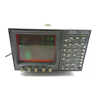
Tektronix B020000 Instruction Manual (212 pages)
Component/Composite Waveform Monitor (SN B020000 and Up)
Brand:
Tektronix
| Category:
Monitor
| Size: 7 MB
Table of Contents
Instruction Manual
1
Contacting Tektronix
5
General Safety Summary
15
Service Safety Summary
55
Using the Replaceable Electrical Parts List
139
Section 8 Replaceable Electrical Parts
139
Column Descriptions
140
Replaceable Electrical Parts
141
Block Diagram
176
Vertical Input
179
Vertical Gain
181
Vertical Output
183
Using the Replaceable Mechanical Parts List
203
Section 10 Replaceable Mechanical Parts
203
Tektronix B020000 User Manual (144 pages)
Component Digital Sync Generator
Brand:
Tektronix
| Category:
Inverter
| Size: 0 MB
Table of Contents
Table of Contents
7
Figure 1-1: Front and Rear Panels of the SPG 422
17
Figure 1-2: Illustration of the SPG 422 Front Panel
18
Figure 1-3: Illustration of the SPG 422 Rear Panel
19
Table 1-1: Front Panel Control, J13
21
Table 1-2: Front Panel Timeout, S1-2
21
Figure 1-4: Front Rail Mount
22
Figure 1-5: Deep Rackmount and Shallow Rackmount
23
Figure 1-6: Assembly of Rackmounting Hardware
23
Figure 1-7: Installing the Instrument in the Rack Slides
24
Figure 2-1: Front Panel of the SPG 422
27
Figure 2-2: Various Ways to Configure the Genlock Input
28
Figure 2-3: Illustration of the SPG 422 Timing
31
Figure 3-1: Illustration of the SPG 422 Main Menu
36
Figure 3-2: How to Access Menus with the Select Buttons
47
Figure 3-3: the Genlock Menu Structure
49
Figure 3-4: the Serial Bars Menu Structure
50
Figure 3-5: the Serial Audio Menu
53
Table 3-1: Audio Sets Output for each Channel
58
Figure 3-6: Black 1 and 2 Menu Structure
59
Figure 3-7: Black 3 through 6 Menu Structure
60
Figure 3-8: the Serial Signals Menu Structure
61
(Reference for Line Scanning) in the 525/60 System
98
Figure A-1: Timing Relationship between the Digital Video Data
98
Figure A-2: Timing Relationship between the Digital Video Data and the Analog Line Synchronization (Reference for Line Scanning) in the 625/50 System
99
Figure A-3: Relationship between the Digital and Analog Fields, Showing also the Position of the Digital Field-Blanking Interval in the 625 System
100
Figure A-4: Relationship of Video Data/Vertical Sync in the 525 System
101
Table A-3: Output Characteristics for Serial Digital Video Signals
102
Table A-4: Signal Characteristics for Analog Black Outputs
103
Figure A-5: 60 Hz Black Burst with 7.5 IRE Setup
106
Figure A-6: 60 Hz Black Burst with no Setup
107
Figure A-7: 50 Hz Black Burst
107
Table A-6: Signal Characteristics for Serial Bars Output
108
Table A-7: Signal Characteristics for Serial Test Signal
109
Table A-8: Signal Characteristics for AES/EBU Serial
110
Table A-9: Signal Characteristics for AES/EBU Serial
111
Table A-10: Signal Characteristics for Embedded Serial Audio
112
Table A-11: 20-Bit Audio Signal Sample Distribution for
113
Table A-12: 20-Bit Audio Signal Sample Distribution for
114
Table A-13: Audio Channel Status Bits
115
Table A-14: Genlock Function
116
Table A-15: Power Supply
117
Table A-16: Mechanical (Physical) Characteristics
118
Table A-17: Environmental Characteristics
118
Table A-18: Certifications and Compliances
119
Figure A-8: 75% Color Bars - y Channel
121
Table A-1: Encoding Parameters for Serial Digital Video Outputs
96
Table A-2: Timing Relationships for Serial Digital Video Outputs
97
Advertisement
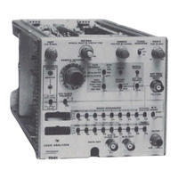
Tektronix B020000 Instruction Manual (134 pages)
LOGIC ANALYZER
Brand:
Tektronix
| Category:
Measuring Instruments
| Size: 77 MB
Table of Contents
Table of Contents
3
Safety Summary
5
Packaging for Shipment
8
Standard Accessories
15
Section 2 Operating Instructions
17
Front Panel Controls
17
Detailed Operating Information
17
Connectors and Indicators
17
Auxiliary Functions
17
Internal Strap Selections
20
Displaying Data
23
Asynchronous and Synchronous
25
Data Sampling
25
Operational Analysis
26
Delay by Words
29
Delay by Events
30
State Table and Mapping Displays
30
Microprocessor Analysis
32
Storage Buffer Analysis
33
Functional Check
33
Section 3 Theory of Operation
39
Block Diagram Description
39
Detailed Circuit Description
41
Front Panel Wiring
41
Vertical Output
47
Horizontal Output
48
Section 4 Maintenance
51
Preventive Maintenance
51
Cleaning . 0
51
Visual Inspection
51
Lubrication
51
Semiconductor Checks
52
Troubleshooting Equipment
53
Troubleshooting Techniques
53
Obtaining Replacement Parts
57
Soldering Techniques
57
Component Removal and Replacement
58
Adjustment after Repair
64
Section 5 Performance Check and Adjustment
65
Preliminary Information
65
Test Equipment Required
65
Preliminary Procedure
67
Performance Check and Adjustment Procedure
69
Section 6 Replaceable Electrical Parts
75
Section 7 Instrument Options
95
Tektronix B020000 Instruction Manual (39 pages)
LOGIC ANALYZER
Brand:
Tektronix
| Category:
Measuring Instruments
| Size: 16 MB
Table of Contents
Table of Contents
3
Glossary
7
Packaging for Shipment
8
7D01 Dimensional Drawing
14
Standard Accessories
15
Section 2 Operating Instructions
17
Front Panel Controls, Connectors and Indicators
17
Detailed Operating Information
17
Auxiliary Functions
17
Front-Panel Controls, Connectors, and
17
Internal Strap Selections
20
Internal Display Clock Source and Full Display/First Trigger Selectors
20
Signal Connections
22
Pin Assignments for Data out
22
Displaying Data
23
Suggested Method for Assembling a
23
Remote Manual Reset Button
23
Clock Qualifier Operation
24
Asynchronous and Synchronous
25
Operational Analysis
26
Applications
29
Fault Identification
29
Delay by Words
29
State Table and Mapping Displays
30
Microprocessor Analysis
32
Typical Setup for Troubleshooting a
32
Storage Buffer Analysis
33
Functional Check
33
Typical Setup and Display for Trouble
33
Section 3 Instrument Options
37
Advertisement
Related Products
Tektronix B020765
Tektronix B086084
Tektronix B040000
Tektronix BPA105
Tektronix B2
Tektronix BB1000-UK
Tektronix BERTScope BSA85C
Tektronix BERTScope BSA175C
Tektronix BERTScope BSA175CPG
Tektronix BERTScope BSA260C
Tektronix Categories
Test Equipment
Measuring Instruments
Amplifier
Portable Generator
Printer
More Tektronix Manuals
Login
Sign In
OR
Sign in with Facebook
Sign in with Google
Upload manual
Upload from disk
Upload from URL