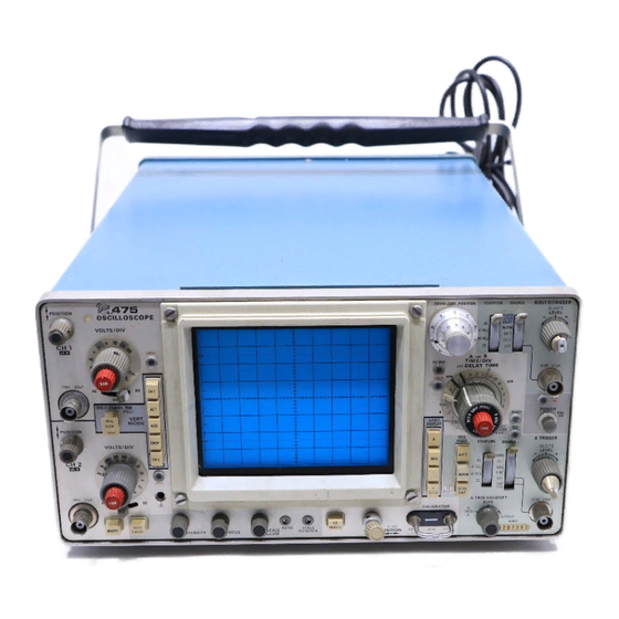
Sign In
Upload
Manuals
Brands
Tektronix Manuals
Test Equipment
475
Tektronix 475 Manuals
Manuals and User Guides for Tektronix 475. We have
6
Tektronix 475 manuals available for free PDF download: Instruction Manual, Technical Manual
Tektronix 475 Instruction Manual (251 pages)
Brand:
Tektronix
| Category:
Test Equipment
| Size: 45.24 MB
Table of Contents
Table of Contents
3
Specification
7
Introduction
7
Vertical Deflection System
7
Triggering
7
Horizontal Deflection System
8
Y Operation
9
Calibrator
9
Z Axis Input
9
Signal Outputs
9
Power Source
9
Cathode-Ray Tube
10
Environmental
10
Supplemental Information
10
Operating Information
13
Introduction
13
Operating Voltage
13
Cathode-Ray Tube (CRT) and Display
14
Controls and Connectors General
14
Vertical Deflection System
14
A and B Triggering
16
A and B Sweep
17
Calibrator and Power
18
Introduction
18
Normal Sweep Display
18
Obtaining Basic Displays
18
Rear Panel
18
Delayed Sweep Display
19
Magnified Sweep Display
19
Mixed Sweep Display
19
Y Display
19
Circuit Description
21
Introduction
21
Digital Logic
21
Block Diagram
22
General
22
Channel 1 Preamp
23
General
23
Input Attenuator
23
Input Coupling
23
First Cascode Amplifier
24
Second Cascode Amplifier
24
Third Cascode Amplifier
24
Channel 2 Preamp
25
Channel Switch 1C
25
First Cascode Amplifier
25
General
25
Vertical Channel Switching Circuit
25
Switching Logic Flip-Flops
26
Two-Megahertz Clock
26
Channel 2 Signal Output Amplifier
27
Chop Blanking Amplifier
27
General
27
Normal Trigger Pickoff Amplifier
27
Scale-Factor Switching Circuits
27
Vertical Output Amplifier
27
First 1C Amplifier
27
Second 1C Amplifier
27
A Trigger Generator
27
Trigger Source
28
Trigger Coupling
28
Input Source Follower
28
Paraphase Amplifier
28
Tunnel Diode Driver
29
Trigger View Amplifier
29
B Trigger Generator
29
General
29
Trigger Source
29
Sweep and Z Axis Logic Circuit
29
Main Gate Comparator
30
Delayed Gate Comparator
30
A Trigger TD Reset Circuit
30
Holdoff Start Circuit
30
Z Axis Logic Multivibrator
31
Delayed Sweep Latch
31
B Trigger TD Reset Circuit
31
Delayed Sweep Override Amplifier
31
A +GATE and B +GATE Amplifiers
31
Sweep Generators
32
General
32
Delaying Sweep Generator
32
Main Gate Amplifier
32
Sweep Disconnect Amplifier
32
Sawtooth Sweep Generator
33
Sweep Start Amplifier
33
Output Buffer Amplifier
33
Logic Comparator
33
Delay Pickoff Comparator
33
Non-Delaying Sweep Generators
34
B " Gate Amplifier
34
Non-Delaying Sweep Generator Differences
34
Mixed Mode Operation
34
Logic Comparator
34
Horizontal Amplifier
35
General
35
Input Paraphase Amplifier
35
Gain Setting Amplifier
35
Output Amplifier
36
CRT Circuit
36
High-Voltage Oscillator
36
High-Voltage Regulator
38
High-Voltage Rectifiers and Output
39
CRT Control Circuits
39
Z-Axis Amplifier
39
DC Restorer Circuit
40
Calibrator
40
General
40
Multivibrator
40
Output Amplifier
40
Fan Motor Circuit
40
Maintenance
41
Cabinet Removal
41
Low-Voltage Power Supply
36
General
36
Power Input
36
Secondary Circuit
36
Preventive Maintenance
41
General
41
Cleaning
41
Lubrication
42
Transistor Checks
42
Recalibration
42
Corrective Maintenance General
42
Obtaining Replacement Parts
42
Soldering Techniques
43
Component Replacement
43
Vertical Preamp Circuit Board Removal
43
Vertical Mode Switch Circuit Board Removal
44
Trigger Generator and Sweep Logic Circuit Board Removal
44
Sweep Timing Circuit Board Removal
45
Recalibration after Repair
45
Instrument Repackaging
45
Calibration
47
Calibration Interval
47
Tektronix Field Service
47
Using this Procedure
47
Test Equipment Required
47
General
47
Special Calibration Fixtures
47
Calibration Equipment Alternatives
47
Preliminary Control Settings
50
Performance Check/Introduction
51
Performance Check
51
Introduction
51
Preliminary Procedure
51
Vertical System Check
52
Check Beam Finder Operation
52
And 2 Gain
53
And 2 Position Range
53
Check Add Mode Operation
53
Check Alternate Mode Operation
54
Check Chop Mode Operation
54
Check Vertical Amplifier Bandwidth
54
Trigger System Check
55
Tr Ig G E R System Check
55
Check Cascaded Bandwidth
55
Check a Triggering
55
Check B Triggering
56
Check a Normal Mode Operation
56
Horizontal System Check
57
H O R Iz O N T a L System Check
57
Check Single Sweep Operation
57
Check Trigger View Operation
57
Check Variable Time/Division Range
57
Check Timing Accuracy
58
Check Delay Time Accuracy
58
Check Delay Time Jitter
59
Check Mixed Sweep Timing Accuracy
59
Check X -Y Phasing and Bandwidth
59
Check X Gain
59
Short-Form Calibration
60
Introduction
60
Preliminary Procedure
60
Power Supplies & Display Calibration
60
Allow at Least 20 Minutes Warmup before Proceeding
60
Set the Controls as Given under Preliminary Control
60
Vertical System Calibration
61
Trigger System Calibration
64
Horizontal System Calibration
65
Calibration
68
Introduction
69
Preliminary Procedure
70
Power Supply C a L Ib R a T Io N
71
Power Supply Calibration
71
Display & Z-Axis Calibration
72
Check High Voltage Power Supply
72
DISPLAY and Z-A XIS CALIB R a TIO N
72
Adjust CRT Grid Bias
72
Adjust Geometry
73
Adjust Trace Alignment
73
Adjust Y-Axis Alignment
73
Check ASTIG Control
73
Check Display Controls
73
Vertical System Calibration
74
Adjust Z-Axis Compensation
74
Adjust Vertical Output Bias
74
Adjust Delay-Line Driver Centering
75
Adjust Vertical Shield Voltage
75
Check BEAM FIN D Operation
75
Check AC-GND-DC Switches
76
Check Probe Indicator Lights
76
Check Channel 2 in V E R T Balance
77
Adjust Vertical Output Amplifier
80
Check a LT Mode Operation
80
Check ADD Mode Operation
80
Check CHOP Mode Operation
80
Check Compression and Expansion
80
Check Cascaded Bandwidth
84
Check Vertical Amplifier Bandwidth
84
Check Bandwidth Limit Operation
85
Check Vertical Channel Isolation
85
T R Ig G E R System C a Lib R a Tio N
86
Adjust a Trigger Sensitivity
86
Adjust B Trigger Sensitivity
86
Trigger System Calibration
86
Adjust a Trigger Centering and
87
Adjust B Trigger Centering and
87
Adjust Trigger DC Balance
87
Check a Internal 40 Megahertz
88
Check B Internal 40 Megahertz
88
Check B Trigger DC Balance
88
Check a External 40 Megahertz
89
Check B External 40 Megahertz
89
Check a Internal 200 Megahertz
90
Check B Internal 200 Megahertz
90
Check HF REJ Triggering
91
Check B 60 Hertz and LF REJ
92
Check a LEV E L Control External
93
Check B le V E L Control External
93
Check Single Sweep Operation
93
Adjust Trigger View Centering
94
Check Automatic Recovery Time
94
Check LINE Triggering
94
Check Normal Mode Operation
94
Adjust Delay Start and Delay Stop
95
Check Trigger View Deflection
95
H O R Iz O N T a L System C a Lib R a Tio N
95
Horizontal System Calibration
95
Adjust Horizontal Amplifier Gain
96
Adjust Magnifier Registration
97
Check VA R T IM E /D IV Range
97
Check Horizontal POSITION Control
97
Adjust 10 Microsecond Timing
97
Adjust 0.1 Microsecond Timing
98
Adjust Horizontal Output Centering
98
Adjust High-Speed Timing-Visual
99
Check Differential Time Accuracy
96
Adjust High-Speed Timing-Current
100
Check T IM E /D IV Accuracy
101
Check a INTEN Timing Accuracy
102
Check Magnified Timing Accuracy
102
Check Delay Time Accuracy
102
Check Delay Time Jitter
103
Check Mixed Sweep Timing Accuracy
103
Adjust X Gain
103
Adjust X -Y Phasing and Bandwidth
104
Check B ENDS a Operation
104
Check a TR IG HO LDOFF Operation
104
C a L IB R a T O R , + GATES, and E X T Z-A XIS CALIB RA
105
Adjust CALIBRATO R Amplitude
105
Check a and B + GATE Outputs
105
Check EXT Z-A XIS Operation
105
Advertisement
Tektronix 475 Technical Manual (217 pages)
Brand:
Tektronix
| Category:
Test Equipment
| Size: 4.87 MB
Table of Contents
Table of Contents
12
Oscilloscope OS-261B(V)1/U and OS-261C(V)1/U
16
Introduction
17
Os-261B(V)1/U
17
General Information and Installation
19
Introduction
19
Characteristics
19
Delay Time and Differential Time Measurement
25
Installation
31
2 Operating Information
33
Preliminary Instructions
33
Introduction
33
Safety Information
33
Operating Power Sources
33
Line Voltage and Regulating Range
33
Options
34
Controls and Connectors
34
General
34
Cathode-Ray Tube (CRT) and Display
34
Vertical Deflection System
34
A and B Triggering
37
Calibrator and Power
39
Rear Panel
40
Obtaining Basic Displays
40
Introduction
40
Normal Sweep Display
40
Magnified Sweep Display
41
Delayed Sweep Displays
41
Mixed Sweep Display
41
X-Y Display
41
Circuit Description
43
Digital Logic
43
Introduction
43
Outline for Circuit Description
43
Basic Block Diagram of the
44
Preamplifier Circuit
44
Instrument
44
Channel 1 Preamp
46
General
46
Input Coupling
47
Input Attenuator
47
First Cascode Amplifier
47
Channel 2 Preamp
48
Second Cascode Amplifier
48
Third Cascode Amplifier
48
General
48
Vertical Channel Switching
49
First Cascode Amplifier
49
General
49
Channel Switch IC
50
Switching Logic Flip-Flops
50
Vertical Output Amplifier
51
Channel 2 Signal Output Amplifier
51
Chop Blanking Amplifier
51
First IC Amplifier
51
General
51
Normal Trigger Pickoff Amplifier
51
Scale-Factor Switching Circuits
51
Two Megahertz Clock
51
A Trigger Generator
52
Atrigger Generator
52
General
52
Second IC Amplifier
52
Input Source Follower
53
Paraphase Amplifier
53
Trigger Coupling
53
Trigger Source
53
Trigger View Amplifier
53
Tunnel Diode Driver
53
B Trigger Generator
54
Btrigger Generator
54
Sweep and Z-Axis Logic
54
General
54
Trigger Source
54
Sweep Control Integrated Circuit
55
A Trigger TD Reset Circuit
56
Delayed Gate Comparator
56
Holdoff Start Circuit
56
Main Gate Comparator
56
Z Axis Logic Multivibrator
56
A +GATE and B +GATE Amplifiers
57
B Trigger TD Reset Circuit
57
Delaying Sweep Latch Circuit
57
LOWLINE Indicator Circuit
57
Main Sweep Holdoff Gate and Delayed Sweep Override Amplifier
57
Sweep Generators (And) Timing
58
Switching
58
General
58
Sweep Generators
58
Delaying Sweep Generator
59
Main Gate Amplifier
59
Sweep Disconnect Amplifier
59
Delay Pickoff Comparator
60
Delaying Sweep End Difference Amplifier
60
Output Buffer Amplifier
60
Sawtooth Sweep Generator
60
Sweep Start Amplifier
60
B" Gate Amplifier
61
Mixed Mode Operation
61
Non-Delaying Sweep End Difference Amplifier
61
Non-Delaying Sweep Generator Differences
61
Non-Delaying Sweep Generators
61
Horizontal Amplifier
62
General
62
TIME/DIV Functions (Knobs Unlocked)
62
Low-Voltage Power Supply
63
Gain Setting Amplifier
63
General
63
Input Paraphase Amplifier
63
Output Amplifier
63
Switching Circuit
63
50-Volt Supply
65
Power Input
65
Secondary Circuit
65
Crt Circuit
66
110-Volt Supply
66
General
66
High-Voltage Oscillator
67
High-Voltage Regulator
67
Control-Grid DC Restorer
68
CRT Control Circuits
68
High-Voltage Rectifiers and Output
68
Z-Axis Amplifier
68
Calibrator
69
Fan Motor Circuit
69
General
69
Multivibrator
69
Output Amplifier
69
Block Diagram
44
Maintenance
71
Maintenance Section Outline
71
Cabinet and Rack Adapter Removal
72
Standard Cabinet Removal
72
Rack Adapter Removal
73
Rack Adapter Installation
74
Preventive Maintenance
74
Introduction
74
Cleaning
74
Air Filter
75
CRT Face, Filter and Shields
75
Exterior
75
General Interior
75
Switch Contacts
75
Visual Inspection
76
Lubrication
76
Semiconductor Checks
76
Troubleshooting
76
Introduction
76
Troubleshooting Aids
76
Recalibration
76
Troubleshooting Equipment
77
Diagrams
77
Diode Color-Code
77
Resistor Color-Code
77
Semiconductor Lead Configuration
77
Standard Cabinet Installation
73
Color Codes for Resistors and Capacitors
78
Troubleshooting Techniques
80
Check Associated Equipment
80
Check Control Settings
80
Check Instrument Calibration
80
Isolate Trouble to a Circuit
80
Multimeter
80
Semiconductor Tester
80
Test Oscilloscope
80
Variable Autotransformer
80
Visual Check
80
Check Circuit Board Interconnection
81
Check Individual Components
81
Check Voltages and Waveforms
81
Special Troubleshooting Information
84
General
84
Repair and Readjust the Circuit
84
Troubleshooting the L.V. Power Supplies
85
Troubleshooting the High-Voltage Circuit
86
Troubleshooting the Sweep Circuits
86
Corrective Maintenance
88
Introduction
88
Troubleshooting the Horizontal Amplifier
88
Troubleshooting the Vertical System
88
Troubleshooting the Z-Axis Circuit
88
Obtaining Replacement Parts
89
Soldering Techniques
89
Small Component Replacement
90
General
90
Transistor and I.C. Replacement
90
Interconnecting Pin Replacement
91
Circuit Board Replacement
92
Cam Switch Replacement
92
Fuse Replacement
92
Vertical Preamp Board Removal
94
Trigger Generator and Z-Axis Logic Board Removal
95
Fan Motor Board Removal
96
Timing Board Removal
96
Vertical Output Board Removal
96
Inverter Board Removal (Option 7 Only)
97
Power Supply Board Removal
97
Main Interface Board Removal
98
Power Transformer Removal
99
Cathode-Ray Tube Removal
100
Cathode-Ray Tube Installation
101
High-Voltage Multiplier Removal
101
Delay Line Removal
102
Recalibration after Repair
102
Instrument Repackaging
102
5 Performance Check Equipment Alternatives
105
Introduction
105
Using this Procedure
105
Test Equipment Required
105
General
105
Special Calibration Fixtures
105
Performance Check
105
Preliminary Procedure for Performance Check
108
Operating Temperature
108
Operating Voltage
108
Power Source
108
Warm up
108
Display and Vertical System Check
109
Trigger System Check
113
11. Check a Low-Frequency Triggering
113
12. Check B Low-Frequency Triggering
115
13. Check B 40 Megahertz Triggering
116
14. Check a 40 Megahertz Triggering
116
Check a 200 Megahertz Triggering
117
16. Check B 200 Megahertz Triggering
117
17. Check TRIG MODE NORM Operation
118
18. Check TRIG MODE SINGL SWP Operation
118
Check TRIG VIEW Operation
118
Horizontal System Check
119
20. Check VAR TIME/DIV Range
119
22. Check a Timing Accuracy
120
23. Check a INTEN Timing Accuracy
120
24. Check a INTEN Magnified Timing Accuracy
120
25. Check a Magnified Timing Accuracy
120
Check Sweep Length and Horizontal POSITION Range
120
26. Check Differential Delay Time Accuracy
121
27. Check Delay Time Jitter
122
28. Check MIX (Mixed Sweep) Timing Accuracy
122
Gate Outputs, External Z-Axis and Calibrator Checks
123
29. Check X Gain
123
30. Check X Bandwidth
123
31. Check a and B +GATE Outputs
124
32. Check CH 2 VERT SIGNAL out
124
33. Check EXT Z-AXIS Operation
124
34. Check CALIBRATOR Operation
124
6 Schematic Diagrams & Options 04 and
125
7 Replaceable Mechanical Parts
135
Appendix A References
169
Introduction
171
Integral Components of End Item
174
Maintenance Allocation
179
D-2 Maintenance Function
179
Column Entries
180
Tool and Test Equipment Requirement
180
Circuit
181
Appendix C Additional Authorization List
181
Maintenance Allocation Chart
181
Oscilloscope
183
Oscilloscope OS-261B(V)1/U and
184
Remarks
185
Appendix Eexpendable Supplies and Materials List Introduction
187
E-1 . Scope
187
Explanation of Columns
187
Expendable Supplies and Materials
188
Tektronix 475 Instruction Manual (72 pages)
Brand:
Tektronix
| Category:
Test Equipment
| Size: 14.17 MB
Table of Contents
Table of Contents
3
Before Operating
7
Introduction
7
Safety Information
7
Operating Voltage
8
Horizontal, Calibrator, and Power 1
8
Options
9
Vertical
10
Rear Panel 1
10
Display
13
Dm43 / Dm40
13
Delayed Sweep Display 1
13
Trigger
14
Mixed Sweep Display 1
14
Single Sweep Display 1
15
Side Panel 1
21
Basic Oscilloscope Displays
22
Normal Sweep Display 1
22
Y Display
24
Resistance
26
Volts
28
Temperature ( Dm43 Only)
30
Applications and Measurements
34
Preliminary
34
Operator's Adjustments and Checks
35
Peak- To- Peak Voltag Emeasurements Ac
37
Instantaneous Voltage Measurements -DC
38
Algebraic Addition
40
Common - Mode Rejection
41
Amplitude Comparison Measurements
42
Time Duration Measurements
43
Frequency Measurements
44
Risetime Measurements
45
Time- Difference between Two
46
Pulses from Different Sources
46
Time Comparison Measurements
47
Basic 475 Delayed or Mixed Sweep Time Measurements
48
Tim E DI Fference Bet Ween Repet It Ive Pulses ( Basic 475 )
48
Ti M E Durat Ion Measurem Ent S ( Basic 475 )
49
Frequency ( Basic 475 )
50
Ti M E DI Fference Bet Ween Two Pulses from Different Sources ( Basic 475 )
51
Riset IM E ( Basic 475 )
53
MIX ( Basic 475 )
54
Dm43 / Dm40 Delayed or Mixed
54
Sweep Time Measurements
54
Pulses ( DM43 / DM40 )
54
Ti M E Durat Ion ( DM43 / DM40 )
55
Frequency ( DM43 / DM40 )
56
Different Sources ( DM43 / DM40 )
57
Riset IM E ( DM43 / DM40 )
58
MIX ( DM43 / DM40 )
59
Delayed or Mixed Sweep Magnification
59
Magnified Sweep St Art S Aft er Delay
59
Tri Ggered Delayed Sweep Magnificat Ion
61
Phase Difference Measurements
62
High Resolution Phase Difference Measurements
63
Pulse Jitter Measurements
64
Operator's Specifications
65
Vertical
65
Triggering
66
Differential Time
66
Measurement ( Basic 475 )
66
Differential Time
67
Measurement ( Dm43 / Dm40 )
67
Horizontal
67
Calibrator
67
Z Axis Input
68
Outputs
68
Resistance Dm43 / Dm40
68
Time Dm43 / Dm40
68
Temperature- Dm43 Only, with Probe
69
DC Voltage Dm43 / Dm40
69
Ac Power Source
70
Environmental
70
Accessories
71
Standard Accessories Included
71
Optional Accessories
71
Options
72
Advertisement
Tektronix 475 Instruction Manual (55 pages)
Brand:
Tektronix
| Category:
Test Equipment
| Size: 14.47 MB
Table of Contents
Table of Contents
3
Introduction
4
Operating Voltage
4
Controls and Connectors
6
Applications
15
General
15
Peak-To-Peak Voltage Measurements-AC
15
Instantaneous Voltage Measurements-DC
17
Comparison Measurements
18
Time-Duration Measurements
21
Frequency Measurement
23
Risetime Measurements
23
Time-Difference Measurements
24
Delayed or Mixed Sweep Time Measurement
26
Delayed or Mixed Sweep Magnification
28
Pulse Jitter Measurements
31
Delayed Trigger Generator
32
Normal Trigger Generator
33
Multi-Trace Phase Difference Measurements
33
High Resolution Phase Measurements
35
X-Y Phase Measurement
36
Common-Mode Rejection
37
Operational Features
38
General
38
Intensity Control
39
Graticule
39
Vertical Mode of Operation
39
Deflection Factor
41
Ground Considerations
41
Input Coupling
42
Trigger Source
43
Trigger Coupling
44
Trigger Slope
44
Trigger Level
45
A Sweep Triggered Light
45
A Trigger Mode
45
A Trigger Holdoff
46
Horizontal Mode of Operation
47
Horizontal Sweep Rates
47
Sweep Magnification
48
External Horizontal (X-Y) Operation
49
Output Signals
49
Intensity Modulation
50
Calibrator
50
Obtaining Basic Displays Introduction
51
Normal Sweepdisplay
51
Magnified Sweep Display
52
Delayed Sweep Displays
52
Mixed Sweep Display
53
X-Y Display
53
User's Calibration
54
General
54
TRACE ROTATION Adjustment
54
Vertical GAIN
54
Probe Compensation
54
Basic Timing Accuracy
55
External Horizontal Gain Accuracy
55
Tektronix 475 Instruction Manual (39 pages)
Oscilloscope and digital multimeter
Brand:
Tektronix
| Category:
Measuring Instruments
| Size: 6.44 MB
Table of Contents
Table of Contents
2
List of Illustrations
3
List of Tables
4
Before Operating
5
Sa Fety Information
5
OP ERATING Voltage
5
Co Nn Ect O R S
6
Trigger
8
Trace Rota Tio N
8
Display
8
Controls,Co Nnectors,And
6
Tim Eand
8
Calib Rator
10
Rear Panel
11
Left Side Panel
11
Right Side Panel
11
Regulating Range Selector
11
(Co Ni)
12
Basic Oscilloscope Displays
12
Magn if Ied
13
Normal Sweep Display
13
Delayed Sweep Display
13
Mixed Sweep Display
13
A N D Mea Su Rements
14
Temperature
16
Accuracy Check
16
Applications and Measurements
18
Signal Ground
18
Input Coupling C Apacitor Precharging
18
Pro be Com Pensation
19
DM44 T Iming Chec K
19
Instantaneous Vo Ltag E
20
Measurements-DC
20
Sweep Display
20
Peak-To-Peak Voltage Measurements- Ac
20
Algebra IC Addition
21
Am Plitude Comparison
22
Measurements
22
Duration Mea Surements
23
Frequency Measurements (B.&.Sic 475)
23
Ti Me du Ra T Ion Me Asurements
23
Vertical
23
Difference
24
Different Sources
24
Fig
24
Pha Se
25
Itt er
26
Pulse Jitte R
26
Delay Ed
27
Magnif Ica T Ion
27
Bas IC 475)
28
TIME D if
28
Frequency Measurements
29
Time Duration Mea Surements
29
Pulses from Different
30
Riset IM
30
Dis Play
31
Frequ Ency Measur Ements
33
Ti Me Difference Bet Ween Two
30
475/DM44 Oper alors
34
Risetime (DM 44)
34
475 Oscilloscope
35
Operator's Specifications
35
DI Fferential Ti Me Mea Su Rem Ent
36
Ac Power Sou
37
DC Voltage
37
Outputs
37
Accessori es
38
Opt Io Na
38
Options
39
Rev Ajan
38
Tektronix 475 Instruction Manual (77 pages)
Oscilloscope, digital multimeter
Brand:
Tektronix
| Category:
Measuring Instruments
| Size: 15.77 MB
Table of Contents
Table of Contents
3
List of Illustrations
6
Basic
6
Before Operating
9
Safety Information
9
Operating Voltage
10
Controls, Connectors
12
Horizontal, Calibrator
20
Left Side Panel
22
Right Side Panel
22
Sweep Display
26
Mixed Sweep Display
26
Single Sweep Display
27
Dm44 Displays
28
Accuracy Check
32
Time and
35
Applications and Measurements
36
Signal Ground
36
Sweep Display
65
Advertisement
Related Products
Tektronix 475A
Tektronix 465
Tektronix 420
Tektronix 460
Tektronix 466
Tektronix 464
Tektronix 485
Tektronix 453A
Tektronix 455
Tektronix 432
Tektronix Categories
Test Equipment
Measuring Instruments
Amplifier
Printer
Portable Generator
More Tektronix Manuals
Login
Sign In
OR
Sign in with Facebook
Sign in with Google
Upload manual
Upload from disk
Upload from URL