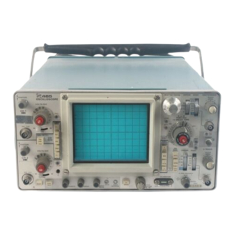
Sign In
Upload
Manuals
Brands
Tektronix Manuals
Test Equipment
465
Tektronix 465 Manuals
Manuals and User Guides for Tektronix 465. We have
2
Tektronix 465 manuals available for free PDF download: Instruction Manual
Tektronix 465 Instruction Manual (252 pages)
Wth Options, SN B250000 & Up
Brand:
Tektronix
| Category:
Test Equipment
| Size: 46.14 MB
Table of Contents
Table of Contents
3
List of Illustrations
7
List of Tables
7
Product View
8
Specifications
9
Vertical Deflection System
9
Triggering
9
Deflection Factor
9
Introduction
9
Horizontal Deflection System
10
X-Y Operation
10
Calibrated Sweep Range/Accuracy
10
Delay or Differential Time Jitter
10
Z-Axis Input
11
Signal Outputs
11
Supplemental Information
11
Calibrator
11
Power Source
11
Cathode Ray Tube (Crt)
11
Vertical Deflection System
11
Calibrator
12
External Z-Axis Input
12
Output Resistances
12
Cathode Ray Tube (CRT)
12
Triggering
12
Horizontal Deflection System
12
Operating Information
13
Instrument Repackaging
13
Operating Voltage
13
Regulating Ranges
13
Introduction
13
Controls and Connectors
14
Cathode Ray Tube (CRT) and Display
14
Power Supply Regulating Range Selector
14
Introduction
14
Vertical Deflection System
14
Front and Rear Panel Controls and Connectors
15
Operating Informatlon
16
A and B Triggering
16
A and B Sweep
17
Obtaining Basic Displays
18
Calibrator and Power
18
Rear Panel
18
Normal Sweep Display
18
Introduction
18
Magnified Sweep Display
19
Delayed Sweep Display
19
Mixed Sweep Display
19
X-Y Display
19
Circuit Description
20
Block Diagram
20
Digital Logic
20
Introduction
20
Basic Block Diagram of the 465
21
Channel 1 Preamp
22
Detailed Block Diagram of the Channel 1 Preamplifier
22
Introduction
22
Scale-Factor Switching Circuit
23
Input Coupling
23
Input Attenuator
23
Source Follower
23
Channel 2 Preamp
24
First Cascode Amplifier
24
Second Cascode Amplifier
24
Introduction
24
Third Cascode Amplifier
25
Diode Gates
25
Detailed Block Diagram Ol the Channel 2 Preamplifier
25
Vertical Switching Circuit
25
Introduction
25
Switching Multlvlbrator
26
Channel 2 Display Only
26
Alternate Trace Display
26
Detailed Block Diagram of the Vertical Switching Circuit
26
Diode Gates
26
Chopped Mode Operation
27
Effect of Diode Gates on Signal Path
27
Added Mode Operation
28
Delay -Line Driver
28
Reference Feedback Amplifier
28
Normal Trigger Pickoff
28
Introduction
28
Vertical Output Amplifier-Discrete Version
28
A and B Trigger Generators
29
Vertical Output Amplifier-IC Version
29
Trigger Source
29
Input Source Follower
29
Introduction
29
Trigger Coupling
29
Paraphase Amplifier
29
A and B Sweep Generator
30
Tunnel Diode Driver
30
Detailed Block Diagram of the a Sweep Generator
30
Introduction
30
Disconnect Amplifier
31
Sawtooth Generator
31
Output Buffer Amplifier
31
Sweep Start Amplifier
31
Logic Multivibrator
31
Sweep and Z Axis Logic Circuit
32
Sweep Control Integrated Circuit
32
Introduction
32
A Sweep Gate
32
B Sweep Gate
32
Holdoff Timing
33
A Sweep Holdoff Amplifier
33
B Sweep Holdoff Amplifier
33
B Sweep Latch
33
A Sweep Z Axis Gate
33
B Sweep Z-Axis Gate
34
A + Gate and B - Gate Emitter Followers
34
X- Axis Amplifier
34
Horizontal Amplifier
34
Introduction
34
Input Paraphase Amplifier
35
Gain Setting Amplifier
35
Output Amplifier
35
Detailed Block Diagram of the Horizontal Amplifier
35
CRT Circuit
36
Detailed Block Diagram of the CRT and Z-Axis Circuits
36
Introduction
36
High Voltage Oscillator
36
CRT Control Circuits
37
High Voltage Regulator
37
High Voltage Rectifier and Output
37
Z Axis Ampliflfer
37
DC Restorer Circuit
38
Multlvibrator
38
Detailed Block Diagram of the Calibrator Circuit
38
Introduction
38
Output Amplifier
38
A Trigger View Amplifier
39
Power Input
39
Secondary Circuit
39
Introduction
39
Low Voltage Power Supply
39
Detailed Block Diagram of the Low Voltage Power Supply
40
Fan Motor Circuit
41
Foldover Circuit Action
41
Preventive Maintenance
42
Cabinet Removal
42
Cleaning
42
Introduction
42
Visual Inspection
43
Switch Contacts
43
Exterior
43
Crt
43
Troubleshooting
44
Recalibration
44
Troubleshooting Aids
44
Troubleshooting Charts
44
Lubrication
44
Semiconductor Checks
44
Introduction
44
Color Codes
45
Troubleshooting Equipment
46
Troubleshooting Techniques
46
Capacitor Markings
46
Diode Color-Code
46
Check Instrument Calibration
47
Isolate Trouble to a Circuit
47
Check Voltages and Waveforms
47
Check Individual Components
47
Corrective Maintenance
48
Obtaining Replacement Parts
48
Repair and Readjust the Circuit
48
Standard Parts
48
Introduction
48
Soldering Techniques
49
Special Parts
49
Ordering Parts
49
Component Removal and Replacement
50
Circuit Boards
50
Vertical Preamp Assembly
50
Trigger Generator and Sweep Logic Circuit Board
51
Sweep Timing Circuit Board
51
Power Transformer
52
Cathode Ray Tube
52
High Voltage Multiplier
53
Transistors and Integrated Circuits
54
Interconnecting Pins
54
Recalibration after Repair
55
Ceramic Terminal Strips
55
Instrument Repackaging
55
Index to Performance Check
56
Equipment Required
56
Test Equipment Alternatives
56
Purpose
56
Limits and Tolerances
56
Line Voltage Selection
56
Special Fixtures
56
Triggers
57
Horizontal
57
Vertical
58
Control Settings
58
Check Trace Rotation
58
Check Alternate/Chop Mode
58
Check Ch 1 Balances
59
Check Ch 2 Balances
59
Check Position Range and Centering
59
Check Beam Finder Operation
59
Check Ch 1 and Ch 2 Deflection Factor
60
Check Ch 1 and CH 2 Variable Volts/Division Range
60
Check Output Amplifier Low Frequency Compensation
60
Check Ch 1 and Ch 2 Volts/Division Compensation
60
Check Ch 1 and Ch 2 Transient Response
61
Check Ch 1 and Ch 2 Bandwidth
61
Check Cascade Gain and Bandwidth
61
Check a and B Internal Triggering
62
Triggers
62
Check a and B External Triggering
63
Check a Normal Mode
63
Check Single Sweep
63
Check Trigger View
64
Check a and B Timing Accuracy
65
Horizontal
65
Check a Variable Time/Division Range
66
Check Delay or Differential Time Linearity
66
Check Delay or Differential Time Accuracy
66
Check Delay or Differential Jitter
67
Check Mixed Sweep Accuracy
67
Check a Intensified and B Ends a
67
Check X Gain
67
Check X Bandwidth
68
Calibration
69
Limits and Tolerances
69
Calibration Equipment Alternatives and Partial Procedures
69
Interactions
69
Purpose
69
Step Titles
69
Line Voltage Selectlon
69
Internal Adjustments
69
Display
69
Test Equipment Required
69
Adjustment Interactions
70
Test Equipment Required
71
Index to Calibration Procedure
73
Power Supply
76
Check/Adjust Power Supply DC Levels, Regulation and Ripple
76
Low Voltage Power Supply Limits
76
Check/Adjust High Voltagte Supply
77
Typical Low Voltage Power Supply Ripple
77
Display and Z Axis
78
Check/Adjust CRT Grid Blas
78
Check/Adjust Trace Alignment
78
Check/Adjust Y-Axis Alignment
79
Check/Adjust Geometry
79
Check/Adjust Z-Axis Compensation
79
Vertical
80
Check Probe Coding Indicator Lights
81
Check Ch 1 and Ch 2 Gate Current
81
Check AC-GND-DC Switches
81
Check Alternate Mode
81
Adjust Output Amplifier Bias
82
Check/Adjust Vertical Output Centering and Beam Finder
82
Check/Adjust Ch 1 Step Attenuator Balance
82
Check/Adjust Ch 1 Variable Volts Division Balance
82
Check/Adjust Ch 2 Step Attenuator Balance
83
Check/ Adjust Ch 2 Variable Volts/Division Balance
83
Check/Adjust Ch 2 Invert Balance
83
Check/Adjust CH 2 Position Centering
83
Check/Adjust Ch 1 and Vertical Output Gain
84
Check/Adjust Ch 2 Gain
84
Check Ch 1 Ch 2 Variable Volts/Division Range
84
Vertical Deflection Factor
84
Check Add Mode
85
Check Compression and Expansion
85
Check/Adjust Vertical Output Low Frequency Compensation
85
Check/ Adjust Ch 1 Volts/Division Compensation
86
Check/Adjust Ch 2 Volts/Division Compensation
86
Check/Adjust Ch 2 and Vertical Output High Frequency Compensation
87
Check Ch 2 Position Effect
87
Check/Adjust Ch 2 10 MV and 20 MV High Frequency Compensation
88
Check/Adjust Ch 1 High Frequency Compensation
88
Check Ch 1 Position Effect
89
Check/Adjust Ch 1 10 MV and 20 MV High Frequency Compensation
89
Check Bandwidth
89
Check Cascaded Gain and Bandwidth
90
Check Channel Isolation
90
Check Common-Mode Rejection Ratio
90
Check Bandwidth Limit Operation
91
Check/Adjust a Trigger Sensitivity and Triggered Lamp
92
Triggers
92
Check/Adjust B Trigger Sensitivity
93
Check/Adjust B Trigger Slope and Level Centering
94
Check/Adjust a Trigger Slope and Level Centering
94
Check/Adjust a Trigger DC Levels
94
Check B Trigger DC Levels
95
Check B Internal 25 Megahertz Triggering
95
Check a Internal 25 Megahertz Triggering
96
Check a External 25 Megahertz Triggering
96
Check B External 25 Megahertz Triggering
97
Check Band a External 100 Megahertz Triggering
97
Trigger Coupling
97
Check a Internal 100 Megahertz Triggering
98
Check B Internal 100 Megahertz Triggering
98
Check a and B High Frequency Reject Triggering
99
Check 60 Hertz Internal Triggering
99
Check 60 Hertz External Triggering
100
Check a and B External Trigger Level Ranges
101
Check Line Triggers
101
Check Auto Recovery Time
102
Check/ Adjust Trigger View Centering
102
Check Trigger View Gain
102
Check/Adjust Sweep Start and a Sweep Calibration
103
Horizontal
103
Check/Adjust Horizontal Amplifier Gain
104
Check Sweep Linearity
105
Check/Adjust Magnifier Registration
105
Check/Adjust B Sweep Calibration
105
Check a Sweep Length
105
Check/Adjust a 10 Microsecond Timing
106
Check/Adjust a Sweep High Speed Timing
106
Check/Adjust B Sweep High Speed Timing
106
Check a and B Time/Division Accuracy
107
Check/Adjust High Speed Magnified Timing
107
Check a and B Magnified Timing Accuracy
107
Check Delay or Differential Time Jitter
108
Differential Time Accuracy
108
Check/Adjust X Gain
109
Check X-Y Phasing and Bandwidth
109
Check B Ends a
109
Check a Trigger Holdoff
109
Gates, Calibration and Ext Z Axis
111
Check a and B Gates
111
Check/Adjust Calibrator DC Level
112
Check External Z Axis
112
Replaceable Electrical Parts
113
Parts Ordering Information
113
Special Notes and Symbols
113
Abbreviations
113
Electrical Parts List
113
Cross Index MFR. Code Number to Manufacturer
114
Option Information
144
465 Option 4 Primary Winding with Power Line Filter
145
Rerplaceable Parts List
146
Safety Considerations
147
Function of Controls and Connectors
147
Operation and Inspection
147
Mode Switch
147
Turn-Off Level Circuit
148
Simplified Block Diagram
148
Turn-Off Circuit
149
Start Circuit
149
Inverter Circuit
149
Option 7 DC Inverter
149
DC Input
150
Start-Stop Switch
150
Power- Mode Switch
150
Option 7 Primary Winding
150
Maintaining Replacement Parts
151
Circuit Board Chassis Removal
151
Typical Battery Pack Disc Discharge Curves
151
Operating Range
152
Inverter Balance
152
Turn -Off Level
152
Circuit Board Layout with Test Voltages
153
Typical Idealized Waveforms
153
Circuit Board Layout with Component Locator Grid
154
Additional Parts Added to Standard 465
155
Replaceable Mechanical Parts
157
Option 7 Exploded
158
Option 78
159
Parts List Changes
159
Semiconductor Lead Configurations
160
Diagrams and Circuit Board Illustrations
161
Symbols and Reference Designators
161
Waveforms
162
Recommended Test Equipment
162
465 Setup
162
465 Control Settings
162
Test Oscilloscope Setup
163
Test Oscilloscope Control Settings
163
DC Voltages
164
A1 and A2 Alternators and A-3 - Vertical Preamp Circuit Boards
166
A4-Vertical Mode Switch Circuit Board
167
Ch1 Vertical Preamp
169
A4 - Vertical Mode Switch Circuit Board
171
CH2 Vertical Preamp
173
Attentuators and A3-Vertical Preamp Circuit Boards
174
A4 Vertical Mode Switching Board
177
A5A - Vertical Output Amplifier Circuit Board
178
A5B-Vertical Output Amplifier Circuit Board
181
A5 Vertical Output Circuit Board
182
A8- Trigger Generator and Sweep Logic Circuit Board
184
AB Trigger Generators
187
A9 - Interface Circuit Board
188
AB Sweep Generators
191
A7 Timing Circuit Board
192
AB Timing Switch
193
A8 - Trigger Generator and Sweep Logic Circuit Board
194
Sweep Axis Logic
197
Horizontal Amplifier
201
A6 - Fan Circuit Board
206
Partial A8 - Trigger Generator and Sweep Logic Circuit Board
207
Partial A9 - Interface Circuit Board
208
A Trigger View, Calibrator Fan
210
Power Supply Isolation Procedure
215
+55 Volt Supply
215
+15 Volt Supply
217
+5 Volt Supply
217
-8 Volt Supply
217
110 Volt Supply Isolation Procedure
219
Interface Circuit Board Adjustment Locations
223
Vertical Preamplifier and Attentuator Circuit Board Adjustment
225
Vertical Output Amplifier Circuit Board Adjustment Locations
226
Trigger Generator and Sweep Logic Circuit Board Adjustment Locations
230
Timing Circuit Board Adjustment Locations
231
Parts Ordering Informations
232
Figure and Index Numbers
232
Indentation System
232
Item Name
232
Oscilloscope
238
Cabinet
247
Accessories
248
Manual Change Information
251
Advertisement
Tektronix 465 Instruction Manual (50 pages)
Brand:
Tektronix
| Category:
Test Equipment
| Size: 3.4 MB
Table of Contents
Table of Contents
3
Introduction
7
Vertical Deflection System
7
Triggering
7
Horizontal Deflection System
8
X-Y Operation
9
Calibrator
9
Z Axis Input
9
Signal Outputs
9
Power Source
9
Cathode-Ray Tube
9
Supplemental Information General
9
Vertical Deflection System
9
Triggering
10
Horizontal Deflection System
10
Calibrator
10
External Zaxis Input
10
Output Signals
10
Cathode-Ray Tube
10
2 Operating Information
11
Introduction
11
Instrument Repackaging
11
Operating Voltage
11
Controls and Connectors
12
General
12
Cathode-Ray Tube (CRT) and Display
12
Vertical Deflection System
12
A and B Triggering
14
A and B Sweep
15
Calibrator and Power
16
Rear Panel
16
Obtaining Basic Displays
16
Introduction
16
Normal Sweep Display
16
Magnified Sweep Display
17
Delayed Sweep Display
17
Mixed Sweep Display
17
X-Y Display
17
3 Circuit Description
18
Introduction
18
Digital Logic
18
Block Diagram
18
General
18
Channel 1 Preamp
20
General
20
Input Coupling
20
Input Attenuator
21
Scale-Factor Switching Circuit
21
Source Follower Stage
21
First Cascode Amplifier Stage
21
Channel 2 Preamp
22
General
22
Second Cascode Amplifier
22
Third Cascode Amplifier
22
CIRCUIT DESCRIPTION (Cont)
23
Vertical Switching Circuit
23
General
23
Diode Gates
23
Switching Multivibrator
24
Delay-Line Driver
25
Reference Feedback Amplifier
25
Normal Trigger Pickoff Amplifier
25
Vertical Output Amplifier General
25
Delay Line
26
Output Amplifier
26
A and B Trigger Generators
26
General
26
Trigger Source
26
Trigger Coupling
26
Input Source Follower
26
Paraphase Amplifier
26
Tunnel Diode Driver
27
A and B Sweep Generators
27
General
27
Disconnect Amplifier
27
Sawtooth Sweep Generator
28
Output Buffer Amplifier
28
Sweep Start Amplifier
28
Logic Multivibrator
28
B Sweep Generator Differences
28
Sweep and Z Axis Logic Circuit
28
General
28
A Sweep Gate
28
B Sweep Gate
29
Sweep Control Integrated Circuit
29
A Sweep Holdoff Amplifier
30
B Sweep Holdoff Amplifier
30
A Sweep 2-Axis Gate
30
B Sweep Z-Axis Gate
30
A GATE and +B GATE Emitter Followers
30
B Sweep Latch
31
Horizontal Amplifier
31
General
31
X-Axis Amplifier
31
Input Paraphase Amplifier
32
Gain Setting Amplifier
32
Output Amplifier
32
CRT Circuit
32
General
32
High-Voltage Oscillator
33
High-Voltage Regulator
33
High-Voltage Rectifiers and Output
34
CRT Control Circuits
34
2-Axis Amplifier
34
DC Restorer Circuit
34
Calibrator
35
General
35
Multivibrator
35
Output Amplifier
35
A Trigger View Amplifier
35
I General
35
Amplifier
35
CIRCUIT DESCRIPTION (Cont)
36
Low-Voltage Power Supply General
36
Power Input
37
Secondary Circuit
37
Fan Motor Circuit
37
General
37
Maintenance
38
Cabinet Removal
38
Preventive Maintenance General
38
Cleaning
38
Lubrication
39
Transistors Checks
39
Recalibration
39
Corrective Maintenance
39
General
39
Obtaining Replacement Parts
39
Soldering Techniques
40
Component Replacement
40
Advertisement
Related Products
Tektronix 465M
Tektronix 460
Tektronix 466
Tektronix 464
Tektronix 465B
Tektronix 442
Tektronix 475
Tektronix 4 B Series
Tektronix 432
Tektronix 455
Tektronix Categories
Test Equipment
Measuring Instruments
Amplifier
Printer
Portable Generator
More Tektronix Manuals
Login
Sign In
OR
Sign in with Facebook
Sign in with Google
Upload manual
Upload from disk
Upload from URL