Sign In
Upload
Manuals
Brands
Tektronix Manuals
Test Equipment
2232
Tektronix 2232 Manuals
Manuals and User Guides for Tektronix 2232. We have
6
Tektronix 2232 manuals available for free PDF download: Service Manual, User Manual
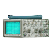
Tektronix 2232 Service Manual (366 pages)
Digital Storage Oscilloscope
Brand:
Tektronix
| Category:
Test Equipment
| Size: 31 MB
Table of Contents
Table of Contents
5
List of Illustrations
7
List of Tables
9
Operators Safety Summary
10
Servicing Safety Summary
11
Introduction
13
Standard Accessories
14
Performance Conditions
14
Electrical Characteristics
15
Performance Requirements
15
Vertical Deflection System
15
Peak Detect
17
Specification
18
Ext Input
19
Horizontal Deflection System
20
Environmental Characteristics
27
Physical Characteristics
29
Line Voltage
31
Power Cord
31
Line Fuse
31
Operating Information
32
Instrument Cooling
32
Repackaging
32
Theory of Operation
33
Section Organization
33
General Description
33
Integrated Circuit Descriptions
33
Digital Logic Conventions
33
MODE Switches
35
Power Supply
38
Communications Options
38
Detailed Circuit Description
39
Introduction
39
Vertical Attenuators
39
Paraphase Amplifier
40
Vertical Preamplifiers
41
Bandwidth Limit
41
Vertical Output Amplifier
44
Delay Line Driver
44
A/B Sweep Separation Circuit
45
Triggering
45
Internal Trigger Amplifier
45
A External Trigger Amplifier
47
Line Trigger Amplifier
48
A Sweep Generator and
49
B Timing and Alternate Bsweep
52
B Miller Sweep Generator
52
B Sweep Logic
54
Alternate Display Switching Logic
55
Horizontal
56
Horizontal Output Amplifier
56
Probe Adjust
58
Memory Space Allocation
60
Status Adc and Bus Interface
61
Storage Acquisition
61
Input Signal Conditioning
61
Analog-To-Digital Conversion
62
Digital Time Base
62
Clock Generator
63
Digital Display
63
Data Transceivers
64
Address Decoder
64
Display Controller
64
Vector Generator
65
Signal Conditioning
66
Digital Acquisition and Memory
66
Power Input, Preregulator and Inverter
67
Start-Up
68
High Voltage
68
Power Supply Secondaries, Z-Axis and Crt
70
External Clock
73
X-Y Plotter
73
Shield Ground
73
Signal Ground
73
Power Supplies
74
Performance Check Procedure
75
Introduction
75
Purpose
75
Performance Check Interval
75
Structure
75
Required
75
Limits and Tolerances
75
Preparation for Checks
75
Test Equipment Required
76
Low-Frequency
76
Vertical
77
Eee
77
Initial Control Settings
78
Procedure Steps
78
Storage Deflection Accuracy
79
Check Store Deflection Accuracy
79
Check Save Expansion and Compression
79
Settings for Bandwidth Checks
80
Check Position Range
80
Check Acquisition Position Registration
80
Check Bandwidth
80
Check Repetitive Store Mode and Bandwidth
81
Check Bandwidth Limit Operation
81
10. Check Common-Mode Rejection Ratio
82
Check Non--Store and Store Channel Isolation 2
82
12. Check Store Pulse Width Amplitude
83
Acquisition Mode
83
Horizontal
84
Settings
84
Procedure Steps
84
Check Timing Accuracy and Linearity
84
Settings for Timing Accuracy Checks
85
Check Store Differential and Cursor Time Difference Accuracy
85
Check Variable Range and Sweep Separation
86
Settings for Delay Time Differential Checks
87
Check Delay Jitter
87
Check Store Expansion Range
88
Check 4K to 1K Display Compress
88
Check Non-Store Sweep Length
88
Check X Gain
88
Check X Bandwidth
88
Trigger
89
Procedure Steps
89
Switch Combinations for a Triggering Checks
89
Check Internal a and B Triggering
89
Check LF Reject a Triggering
90
Check External Triggering
91
Check Single Sweep Operation
91
Trigger Points
92
Check Trigger Level Readout
92
External Z-Axis, Probe Adjust, External Clock, and X--Y Plotter
93
Initial Control
93
Procedure Steps
93
Check External Z-Axis Operation
93
Check Probe Adjust Operation
93
Adjustment Procedure
95
Introduction
95
Purpose
95
Structure
95
Test Equipment Required
95
Limits and Tolerances
95
Adjustments Affected by Repairs
95
Preparation for Adjustment
96
Adjustments Affected by Repairs
96
Index to Adjustment Procedure Steps
97
Power Supply and Crt Display
98
Settings
98
Procedure Steps
98
Power Supply Limits
98
Check/Adjust Power Supply DC Levels
98
Adjust CRT Grid Bias
99
Adjust Astigmatism
99
4, Adjust Trace Alignment
99
Adjust Geometry
99
Vertical
100
Initial Control Settings
100
Procedure Steps
100
Adjust Step Attenuator Balance
100
Adjust 2/5 MV DC Balance
100
Adjust Channel 1 Variable Balance
101
Adjust MF/LF Compensation and Gain Balance
101
Adjust Vertical Gain
101
Adjustment Procedure -2232 Service
101
Deflection Accuracy Limits
102
Check Deflection Accuracy and Variable Range
102
Adjust Acquisition Position Registration
102
Adjust-Ch1 Gain
103
Adjust-Ch2 Gain
103
Check Store Deflection Accuracy
103
Store Deflection Accuracy
104
Adjust Store y Offset and Gain
104
Adjust Acquisition Position Offset
104
Attenuator Compensation Adjustments
105
Adjust Attenuator Compensation
105
Adjust High-Frequency Compensation
105
Compensation
106
Adjust 2 MV Peaking Compensation
106
Adjust Acquisition High-Frequency Peaking
106
Check Bandwidth Limit Operation
107
Check Bandwidth
107
Check Repetitive Store Mode and Bandwidth
107
Horizontal
109
Initial Control Settings
109
Procedure Steps
109
Adjust Horizontal Amplifier Gain
109
Adjust X10 Horizontal Amplifier
109
Adjust Magnifier Registration
110
Adjust/Check 4K to 1K Display Compress
110
Adjust High-Speed Timing
111
Adjust 5 Ns Timing and Linearity
111
Check Timing Accuracy and Linearity
111
Settings for Timing Accuracy Checks
112
Check Delay Time Differential ACCUIACY
112
Adjust Vector Generator
113
Adjust Store X Offset and Gain
113
Adjust Horizontal Position Registration
113
Check Store Differential and Cursor Time Difference Accuracy
113
Adjustx Gain
114
Check A-Sweep Holdoff
114
Trigger
115
Initial Control Settings
115
Procedure Steps
115
Adjust Channel 1 Trigger Offset
115
Adjust a and B Trigger Sensitivity
116
Adjust P-P Auto Level
116
Adjust Trigger Level Readout
116
Maintenance
117
Static-Sensitive Components
117
Relative Susceptibility to Static-Discharge Damage
117
Preventive Maintenance
118
Introduction
118
General Care
118
Inspection and Cleaning
118
External Inspection Checklist
118
Internal Inspection Checklist
119
Lubrication
120
Semiconductor Checks
120
Periodic Readjustment
121
Troubleshooting
121
Introduction
121
Troubleshooting Aids
121
Troubleshooting Equipment
126
Troubleshooting Techniques
126
AC GND DC Switch Interface Voltages
127
Power Supply Voltage and Ripple Limits
129
Diagnostics
131
Diagnostic Tests and Messages
131
Advanced Functions
132
Error Codes for PU Test
134
Probe Coding
135
Corrective Maintenance
138
Introduction
138
Maintenance Precautions
138
Obtaining Replacement Parts
138
Specification
139
Maintenance Aids
139
Interconnections
140
Lithium Battery (Bt1101)
140
Transistors and Integrated Circuits
140
Soldering Techniques
140
Removal and Replacement Instructions
142
Cathode-Ray Tube
145
Power-Supply Shield
146
Graticule Intensity
151
Introduction
153
Options Description
153
International Power Cord
153
Options
153
Option 10
153
Option 12
153
Option 33
153
Servicing Information
153
Operation
153
Line Drivers
154
Parameter Buffer
154
GPIB Status Buffer Functions
155
Bus Buffers
155
Performance Check
156
Procedure
156
RS-232-C Status Buffer FUNCTIONS
156
Test Equipment Required
157
Adjustment Procedure
158
Information
158
Replaceable Electrical Parts
161
Change Information
161
Cross Index - Mfr. Code Number to Manufacturer
162
Diagrams and Circuit Board Illustrations
255
2232 Service
256
Mechanical Parts
325
Indentation System
325
Optional Accessories
342
Revision Information
344
Replaceable Mechanical Parts
345
Manual Change Information
348
Digital Acquisition
355
Acquisition Memory
355
External Clock Divider
355
Ram Registers
356
Delay Timer
357
Advertisement
Tektronix 2232 User Manual (388 pages)
PORTABLE OSCILLOSCOPE
Brand:
Tektronix
| Category:
Test Equipment
| Size: 9 MB
Table of Contents
Section 7-Performance Characteristics
7
Section 8-Options and Accessories
7
Change Information
9
Table of Contents
10
Terms in this Manual
15
Terms as Marked on Equipment
15
Symbols as Marked on Equipment
15
Use the Proper Fuse
16
Do Not Remove Covers or Panels
17
Accuracy and Resolution
23
Standard Accessories
25
Power Cord
29
Optional Power Cord Data
31
Instrument Cooling
32
Controls, Connectors and Indicators
35
Vertical Controls and Connectors
39
Save Reference/Menu Items Select Buttons
63
Rear Panel
65
Ext Clock
72
DISPLAY Menu
73
REFERENCE Menu (Format Selected)
78
PLOT Menu
80
Crt Readout
82
Crt Readout Display
83
Basic Operation
89
Coaxial Cables
91
Initial Setup
95
Trace Rotation Adjustment
96
Horizontal Accuracy Check
99
Graticule Measurement Markings
100
Normal Sweep Display
104
Single Sweep Display
107
STORE Mode Display
108
Ground-Referenced Voltage Measurement
115
Amplitude Comparison
119
Time Duration
121
Rise Time
123
Time Difference between Two Time-Related Pulses
125
Phase Difference
128
High-Resolution Phase Difference
130
Delayed-Sweep Magnification
134
Time Difference between Repetitive Pulses
138
Time Difference between Two Time-Related Pulses
141
Ground-Referenced DC Voltage, Cursor Method
148
Rise Time, Cursor Method
152
Waveform Comparison
153
Time Difference between Repetitive Pulses
155
Phase Difference
158
Anti-Aliasing
168
Glitch Display, ACCPEAK Store Mode
169
Peak Detect
182
Triggering System
185
EXT INPUT Connectors
186
Horizontal Deflection System
187
CHOP or ALT
190
X-Yoperation
195
Power Supply
197
Crt Display
197
Power Cord Options
206
Option 10 Gpib Operators Information
208
Standard Functions, Formats, and Features
208
Option 10 Side Panel
211
Option 12 Side Panel
211
GPIB Parameter Selection
216
GPIB Programming
221
Service Request
222
Option 12Rs-232-Coperators Information
223
Option 12 Interface Status Indicators
231
Remote-Local Operating States
235
Communication Commands
255
Performance Check Interval
297
Limits and Tolerances
300
Procedure Steps
304
Check Deflection Accuracy and Variable Range
304
Check Store Deflection Accuracy
305
Check Save Expansion and Compression
305
Check Position Range
307
Check Non-Store Aberrations
309
Check Store Aberrations
310
Check Bandwidth
311
Check Single Sweep Sample Acquisition
313
Check Bandwidth Limit Operation
313
Check Non-Store and Store Channel Isolation
315
Check Store Pulse Width Amplitude
316
Horizontal
318
Check Timing Accuracy and Linearity
319
Check Variable Range and Sweep Separation
323
Check Delay Time Differential Accuracy
324
Check Delay Jitter
325
Check Position Range
326
Check Store Expansion Range
326
Check 4K to IK Display Compress
327
Check Non-Store Sweep Length
327
Check X Gain
328
Check X Bandwidth
328
Initial Control Settings
329
Check Internal a and B Triggering
330
Check HP Reject a Triggering
332
Check LF Reject a Triggering
333
Check External Triggering
334
Check External Trigger Ranges
334
Check Single Sweep Operation
335
Check Acquisition Window Trigger Points
336
Check Trigger Level Readout
337
Check Probe Adjust Operation
339
Check External Clock
340
Check XY Plotter
341
Rs-232-C Device Interconnection
345
Interconnection Rules
346
Rs-232-C Interconnection Cable-Type Illustrations
348
Plotter Types
358
Using the Power Cord Wrap
383
Installing the Accessory Pouch
385
Tektronix 2232 Service Manual (423 pages)
DIGITAL STORAGE OSCILLOSCOPE
Brand:
Tektronix
| Category:
Test Equipment
| Size: 22 MB
Advertisement
Tektronix 2232 User Manual (184 pages)
Digital Storage Oscilloscope
Brand:
Tektronix
| Category:
Test Equipment
| Size: 4 MB
Table of Contents
Warranty
3
Related Manuals
5
Welcome
6
Table of Contents
7
Glossary and Index
10
Symbols and Terms
13
Specific Precautions
14
Installation
15
Initial Setup
16
Setting up the Display
16
Adjusting Trace Rotation
17
Checking the Probe Compensation
18
Installing the Accessory Pouch
19
At a Glance
22
Front Panel
22
Power Switch
24
CRT Display
25
Display Mode
26
CRT Display Controls
28
Trace Rotation
29
Vertical Controls and Connections
30
Horizontal Controls
34
Trigger Controls
36
Ext Input
39
Cursor Controls
40
Select Waveform
40
Acquisition Controls
41
Save Reference Memory Buttons
42
Setup Menus
45
Acquisition Menu
46
Display Menu
48
Format Reference Menu
49
Nvmem Reference Menu
50
Advanced Functions Menu
53
Select Setup
54
Save Setup
55
Applying Signals to the Vertical Inputs
57
Connecting Signals
57
Coupling Signals
58
Precharging the Signal Input
58
Selecting the Display Mode (STORE/NON-STORE)
59
Selecting the Trigger Mode
60
Selecting the Horizontal Mode and Scale
60
Setting the Display Intensity and Focus
62
Finding "Lost" Displays
63
Digitizing Signals
64
Selecting the Acquisition Mode
65
Selecting the High-Speed Storage Mode
65
Viewing Slowly Occurring Events
66
Capturing Random Events
68
Accumulating Signal Peaks (ACCPEAK)
69
Detecting Signal Glitches
69
Averaging Signals
70
Sampling Signals
70
Clocking Acquisitions
71
Selecting the Acquisition Record Length (1K/4K)
71
Compressing the Acquisition Record Length (4K Compress)
72
Positioning the Acquisition Record
73
Preventing Signal Aliases
74
Using the X10 Magnifier
75
Displaying Two Channels
76
Comparing Two Signals
76
Subtracting Signals or Signal Components (Common Mode Rejection)
76
Limiting Bandwidth
81
Modulating the Display Intensity
81
Triggering on Repetitive Signals
82
Triggering on Low-Frequency Signals
83
Triggering on Random or Infrequent Events
83
Triggering on Complex or Non-Repetitive Signals
84
Triggering on Line Frequency
85
Triggering with an External Signal
85
Triggering on TV Signals
85
Vertical Mode
86
Removing Unwanted Trigger Signal Components
87
Measuring with the Graticule
89
Positioning the Cursors
90
Measuring Voltage
90
Measuring Voltages in Reference to Ground
91
Measuring Time with the Graticule or Cursors
93
Measuring Frequency
95
Measuring Trigger Level
98
Measuring Phase Difference
98
Saving and Recalling
101
Saving the Current Acquisition
101
Recalling a Waveform from SAVE REF
102
Comparing Saved Waveforms
102
Saving a Setup
105
Recalling a Setup from Memory
105
Recalling a Power up State
105
Communicating Via Interface Options
107
OPTION 10: GPIB Interface
111
Option 12: Rs-232-C Interface
111
Appendix A: Options and Accessories
112
Other Accessories
113
Vertical System
115
Horizontal System
115
Appendix B: Specification
116
User Interface
116
Measurement Features
117
Characteristic Tables
118
Performance Requirements
118
Vertical Deflection System
118
Peak Detect
120
Trigger System
122
Horizontal Deflection System
124
General Information
135
Performance Check Interval
135
Structure
135
Limits and Tolerances "0.0.0
135
Test Equipment Required
136
Appendix C: Performance Veritication
138
Initial Setup Procedure
138
Vertical System Checks
138
Horizontal System Checks
147
Trigger System Checks
155
Step 5: Check External Trigger Ranges
158
Appendix D: Storage Modes
166
Tektronix 2232 User Manual (186 pages)
Digital Storage Oscilloscope
Brand:
Tektronix
| Category:
Test Equipment
| Size: 35 MB
Table of Contents
Welcome
5
Related Manuals
5
Table of Contents
7
List of Figures
11
Figure 2-24: Nvmem Reference Menu
12
Product Description
15
Before You Begin
16
Symbols and Terms
17
Specific Precautions
18
Setting up the Display
20
Adjusting Trace Rotation
21
Figure 1-2: Initial Setup Display
21
Figure 1-3: Checking Probe Compensation
22
Installing the Accessory Pouch
23
Figure 1-4: Installing the Accessory Pouch
23
Front Panel
26
Power Switch
29
CRT Display Controls
30
Figure 2-5: CRT Graticule
30
Figure 2-7: Digital (STORE) Mode Display
32
Figure 2-8: CRT Display Controls
33
Vertical Controls and Connections
35
Figure 2-10: Vertical Controls and Connections (Cont.)
37
Horizontal Controls
39
Trigger Controls
41
Figure 2-13: Trigger Controls (Cont.)
43
Figure 2-14: Cursor Controls
45
Memory Buttons
47
Figure 2-18: 4K Two-Channel Acquisition, Memory Location 4K
48
Setup Menus
50
Figure 2-20: Setup Menu Example (Display)
51
Figure 2-21: Acquisition Menu
51
Figure 2-22: Display Menu
53
Figure 2-23: Format Reference Menu
54
Figure 2-26: Advanced Functions Menu
58
Save Setup Menu
58
Figure 2-27: Save Setup Menu
60
Displaying Signals
63
Applying Signals to the Vertical Inputs
63
Figure 3-1: Input Connection and Coupling Switch
63
Connecting Signals
63
Coupling Signals
64
Precharging the Signal Input
64
Building a Basic Display
65
Presetting the Controls
65
Selecting the Display Mode (STORE/NON-STORE)
65
Selecting the Horizontal Mode and Scale
66
Figure 3-2: Horizontal Display Controls
66
Selecting the Vertical Mode and Scale
67
Figure 3-3: Vertical Display Controls
68
Setting the Display Intensity and Focus
68
Finding "Lost" Displays
69
Figure 3-4: CRT Display Controls
69
Selecting the Acquisition Mode
71
Selecting Slow-Speed Storage Modes
71
Viewing Slowly Occurring Events
72
Capturing Random Events
74
Accumulating Signal Peaks (ACCPEAK)
75
Detecting Signal Glitches
75
Clocking Acquisitions
77
Selecting the Acquisition Record Length (1K/4K)
77
Compressing the Acquisition Record Length
78
Positioning the Acquisition Record
79
Preventing Signal Aliases
80
Displaying Magnified Sweeps
81
Using the X10 Magnifier
81
Subtracting Signals or Signal Components (Common Mode Rejection)
82
Displaying Two Sweeps
84
Limiting Bandwidth
87
Modulating the Display Intensity
87
Triggering on Signals
88
Triggering on Low-Frequency Signals
89
Triggering on Random or Infrequent Events
89
Triggering on Complex or Non-Repetitive Signals
90
Triggering on Line Frequency
91
Triggering with an External Signal
91
Triggering on TV Signals
91
Removing Unwanted Trigger Signal Components
93
Measuring Signals
95
Measuring with the Graticule
95
Measuring Voltage
96
Measuring Time with the Graticule or Cursors
99
Measuring Frequency
101
Measuring Trigger Level
104
Measuring Phase Difference
104
Saving and Recalling
107
Saving Waveforms and Setups
107
Saving and Recalling Setups
111
Communicating Via Interface Options
113
Transmitting Waveforms
113
Appendix A: Options and Accessories
118
Option 12: Rs-232-C Interface
118
Other Accessories
120
General Product Description
122
Vertical System
122
Horizontal System
122
Characteristic Tables
125
Vertical Deflection System
125
Trigger System
129
Horizontal Deflection System
131
Probe Adjust
136
Power Supply
137
Appendix C: Performance Verification
142
General Information
142
Performance Check Interval
142
Limits and Tolerances
142
Test Equipment
143
Procedures
145
Initial Setup Procedure
145
Vertical System Checks
145
Horizontal System Checks
154
Trigger System Checks
162
External Z-Axis, Probe Adjust, External Clock, and
168
Appendix D: Storage Modes
172
Tektronix 2232 User Manual (187 pages)
Digital Storage
Brand:
Tektronix
| Category:
Test Equipment
| Size: 5 MB
Table of Contents
Table of Contents
11
Figure 2-23: Format Reference Menu
14
Figure 2-25: Plot Menu
14
Figure 1-1 : Installing the Power Cord
21
Table 1-1 : Basic Analog Display Setup
22
Figure 1-2: Initial Setup Display
23
Figure 1-3: Checking Probe Compensation
24
Figure 1-4: Installing the Accessory Pouch
25
Figure 1-5: Using the Power Cord Wrap
26
Figure 2-1 : Front Panel Control Sections
28
Figure 2-4: Power Switch
31
Figure 2-5: CRT Graticule
32
Figure 2-7: Digital (STORE) Mode Display
34
Figure 2-8: CRT Display Controls
35
Figure 2-1 0: Vertical Controls and Connections (Cont.)
39
Figure 2-1 1 : Horizontal Controls
41
Figure 2-1 3: Trigger Controls (Cont.)
45
Figure 2-1 4: Cursor Controls
47
Figure 2-15: Acquisition Controls
48
Figure 2-1 6: Save Reference Memory Buttons
49
Figure 2-1 7: 1 K Two-Channel Acquisition, Memory Location 1
50
Figure 2-1 8: 4K Two-Channel Acquisition. Memory Location 4K
50
Figure 2-19: Setup Buttons
52
Figure 2-22: Display Menu
55
Figure 2-26: Advanced Functions Menu
60
Figure 2-27: Save Setup Menu
61
Figure 3-3: Vertical Display Controls
69
Figure 3-4: CRT Display Controls
70
Figure 3-5: Beam Find
71
Figure 3-6: Scan Mode
74
Figure 3-7: Roll Mode
75
Figure 3-8: Accumulate Peak Mode Display
76
Triggering on Line Frequency
92
Triggering on TV Signals
92
Triggering with an External Signal
92
Removing Unwanted Trigger Signal Components
94
Measuring Signals
96
Measuring with the Graticule
96
Measuring with STORE Mode Cursors
96
Positioning the Cursors
97
Measuring Voltage
97
Measuring Voltages in Reference to Ground
98
Measuring Time with the Graticule or Cursors
100
Measuring Time Using the Delay Time Readout
101
Measuring Frequency
102
Measuring Rise Time and Fall Time
103
Measuring Trigger Level
105
Measuring Phase Difference
105
Saving Waveforms and Setups
108
Saving and Recalling Waveforms
108
Saving the Current Acquisition
108
Saving Waveforms in SAVE REF Memory
108
Recalling a Waveform from SAVE REF
109
Comparing Saved Waveforms
109
Formatting Saved Waveforms
109
Saving Waveforms in Long-Term Memory
110
Saving and Recalling Setups
112
Saving a Setup
112
Recalling a Setup from Memory
112
Recalling a Power up State
112
Transmitting Waveforms
114
Communicating Via Interface Options
114
Plotting or Printing a Waveform
115
Appendix A: Options and Accessories
119
Options
119
Table A-1 : International Power Cords
119
Standard Accessories
120
Table A-2: Standard Accessories
120
Other Accessories
121
Table A-3: Optional Accessories
121
Appendix B: Specification
123
General Product Description
123
Options and Accessories
125
Performance Conditions
125
Characteristic Tables
126
Table A-4: Electrical Characteristics
126
Table A-5: Environmental Characteristics
140
Table A-6: Physical Characteristics
141
Appendix C: Performance Verification
143
General Information
143
Purpose
143
Performance Check Interval
143
Structure
143
Limits and Tolerances
143
Test Equipment Required
144
Table A-7: Test Equipment Required
144
Procedures
146
Initial Setup Procedure
146
Vertical System Checks
146
Table A-8: Deflection Accuracy Limits
148
Table A-9: Storage Deflection Accuracy
149
Table A-1 0: Settings for Bandwidth Checks
151
Horizontal System Checks
155
Table A-1 1 : Settings for Timing Accuracy Checks
158
Table A-12: Settings for Delay Time Differential Checks
161
Trigger System Checks
163
Table A-13: Switch Combinations for a Triggering Checks
164
External Z.axis. Probe Adjust. External Clock. and X-Yplotterchecks
169
Appendix D: Storage Modes
173
Glossary
175
Index
181
Advertisement
Related Products
Tektronix 2230
Tektronix 2235
Tektronix 2236
Tektronix 2235A
Tektronix 2236A
Tektronix 2213
Tektronix 2246 2R
Tektronix 2245A
Tektronix 222
Tektronix 2220
Tektronix Categories
Test Equipment
Measuring Instruments
Amplifier
Portable Generator
Printer
More Tektronix Manuals
Login
Sign In
OR
Sign in with Facebook
Sign in with Google
Upload manual
Upload from disk
Upload from URL