Sign In
Upload
Manuals
Brands
System Sensor Manuals
Control Panel
PDRP-2001E
System Sensor PDRP-2001E Manuals
Manuals and User Guides for System Sensor PDRP-2001E. We have
2
System Sensor PDRP-2001E manuals available for free PDF download: Instruction Manual
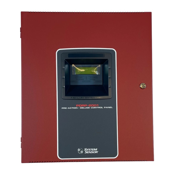
System Sensor PDRP-2001E Instruction Manual (140 pages)
Brand:
System Sensor
| Category:
Control Panel
| Size: 2 MB
Table of Contents
Table of Contents
4
SECTION 1: Product Description
11
Product Features
11
Specifications
13
Controls and Indicators
14
Components
15
Optional Modules and Accessories
16
SECTION 2: Installation
17
Backbox Mounting
17
Operating Power
20
Input Circuits
21
Output Circuits
23
1: Outputs/Notification Appliance/Releasing Circuits
23
2: Special Application DC Power Output Connections
24
3: Relays - Programmable
24
Power-Limited Wiring Requirements
25
Installation of Optional Modules
26
1: CAC-5X Class a Converter Module
26
Installation
26
Wiring Nacs and Idcs for Class a
27
2: 4XTM Municipal Box Transmitter Option Module
28
4XTM Transmitter Module Installation
29
ANN-BUS Devices
30
1: ANN-BUS Wiring
30
Calculating Wiring Distance for ANN-BUS Modules
30
Wiring Configuration
32
Powering ANN-BUS Devices from Auxiliary Power Supply
33
2: ANN-BUS Device Addressing
33
3: ANN-80 Remote LCD Annunciator
34
4: Specifications
34
5: Installation
34
Mounting
34
Opening/Closing Annunciator
34
Wiring ANN-80 to FACP
35
6: ANN-S/PG Serial/Parallel Printer Interface Installation
37
Specifications
37
Printer Installation
37
Connecting PRN-6 Printer
38
Setting Printer Options
38
7: ANN-I/O LED Driver Module
39
ANN-I/O Board Layout
39
Specifications
39
ANN-I/O Connection to FACP
40
ANN-I/O Module LED Wiring
41
8: ANN-LED Annunciator Module
41
ANN-LED Board Layout
42
Specifications
42
Mounting/Installation
42
ANN-LED Connection to FACP
43
9: ANN-RLY Relay Module
44
ANN-RLY Board Layout
44
Specifications
44
Mounting/Installation
44
ANN-RLY Connection to FACP
45
SECTION 3: Programming
46
User Programming
46
Initial Power-Up
47
Programming Screens Description
47
Programming and Passwords
48
Master Programming Level
49
1: FACP CONFIG (Application Templates)
50
2=Input Zones
50
3=Output Circuits
57
Enabled
58
Type
58
Release Circuit 1 or Release Circuit 2
58
Release Stage NAC
59
Silence
59
Auto Silence
60
Silence Inhibited
60
Coding
61
Synchronized NAC Operation
62
4: Cross Input Zones
63
5: On-Board Relays
64
6: System Setup
64
Timers
65
Soak 1 or Soak 2
66
Waterflow Delay
66
AC Loss Delay
67
Banner
67
Time-Date
68
Time
69
Date
69
Clock Format
69
Daylight Savings Time
70
Trouble Reminder
70
Charger Disable
70
7: Ann-Bus
71
ANN-BUS Enabled
71
ANN-BUS Modules
72
Auto-Configure
73
Ann-S/Pg Options
73
ANN-I/O LED Zone Assignments
75
Options
76
ANN-RLY Options
77
8: History
78
View Events
78
Erase History
78
9: Walktest
79
10: Clear Program
80
11: Password Change
80
Maintenance Programming Level
81
1: Input Zones - Enable/Disable
82
2: History
82
3=Walktest
83
4: Time-Date
84
SECTION 4: Operating Instructions
85
Panel Control Buttons
85
1: Acknowledge/Step
85
2: Alarm Silenced
85
3: Drill/Hold 2 Sec
85
4: Reset
85
Indicators
86
Normal Operation
86
Trouble Operation
87
Alarm Operation
88
Supervisory Operation
89
Disable/Enable Operation
89
Waterflow Circuits Operation
89
2Nd-Shot Water Switch
90
Detector Functions
90
Time Functions: Real-Time Clock
90
Coded NAC Operation
90
Release Stages
91
Special System Timers
91
1: Silence Inhibit Timer
91
2: Autosilence Timer
91
3: Trouble Reminder
91
4: Soak Timers
91
5: Waterflow Delay Timer
91
Walktest
91
Read Status
92
2=Input Zones
92
1: FACP Configuration
93
3=Output Circuits
94
4: Cross Input Zones
94
5: On-Board Relays
95
6: System Settings
95
7: Timers
96
8: Daylight Savings
96
9: History
97
10: Ann-S/Pg
97
11: Ann-Bus
98
SECTION 5: Power Supply Calculations
99
Overview
99
Calculating the AC Branch Circuit
99
Calculating the System Current Draw
100
1: Overview
100
2: How to Use Table 5-3 on Page 101 to Calculate System Current Draw
100
Calculating the Battery Size
102
1: NFPA Battery Requirements
102
2: Selecting and Locating Batteries
102
APPENDIX A Circuit Mapping and Cross-Zoning
103
A.1: Input-To-Output Circuit Mapping and Cross-Zone Operation
103
A.1.1: Mapping Input Zones to Output Circuits for Direct Activation
104
A.1.2: Mapping Input Zones to Release Circuits for Cross Zone
105
Activation
105
Release Circuits
107
APPENDIX B: FACP Configuration Templates
108
B.1: Template 7: Single Hazard - 3 Zone
109
B.2: Template 8: Single Hazard - Cross-Zone with Manual Release
110
B.3: Template 9: Dual Hazard - Combined Release
111
B.4: Template 10: Dual Hazard - Split Release
112
B.5: Template 11: Single Hazard - 3 Zones and Low Pressure
113
B.6: Template 12: Single Hazard - 2 Zones Cross-Zoned with All Active
114
B.7: Template 13: Single Hazard - Dual Zone
115
APPENDIX Cnfpa Standard-Specific Requirements
116
C.1: NFPA 72 Auxiliary Fire Alarm System
119
Connection to FACP Dry Contacts
122
APPENDIX D: FACP with Keltron
123
APPENDIX E: Testing & Maintenance
124
E.1: Testing
124
E.1.1: Inspection
124
E.1.2: Alarm Test
124
3: Detector Testing
124
E.2: Maintenance
125
APPENDIX F: Compatible Devices
126
APPENDIX F: Compatible Two-Wire Smoke Detectors (UL Listed)
126
APPENDIX F: Maximum Number of Detectors Per Zone
127
APPENDIX F: Four-Wire Smoke Detectors/Devices (UL Listed)
128
APPENDIX F: Notification Appliances (UL Listed)
129
System Sensor - 24VDC
129
Releasing Applications
130
Door Holders (UL Listed)
130
Relays (UL Listed)
130
Advertisement
System Sensor PDRP-2001E Instruction Manual (132 pages)
PRE-ACTION/DELUGE CONTROL PANEL PDRP-2001 Series
Brand:
System Sensor
| Category:
Control Panel
| Size: 2 MB
Table of Contents
Installation Precautions
3
Table of Contents
5
Section 1: Product Description
12
Product Features
12
Specifications
13
Controls and Indicators
16
Function Keys
16
Components
17
Optional Modules and Accessories
17
Section 2: Installation
19
Backbox Mounting
19
Operating Power
22
Input Circuits
24
Output Circuits
26
1: Outputs/Notification Appliance/Releasing Circuits
26
2: Special Application DC Power Output Connections
27
3: Relays - Programmable
27
Power-Limited Wiring Requirements
28
Installation of Optional Modules
29
1: CAC-5X Class a Converter Module
29
Installation
29
Wiring Nacs and Idcs for Class a
30
2: 4XTMF Municipal Box Transmitter Option Module
31
4XTMF Transmitter Module Installation
31
3: ANN-SEC Option Card
33
ANN-BUS Devices
33
Guidelines
33
1: ANN-BUS Wiring
34
Calculating Wiring Distance for ANN-BUS Modules
34
Wiring Configuration
36
Powering ANN-BUS Devices from Auxiliary Power Supply
36
2: ANN-BUS Device Addressing
37
3: ANN-80 Remote LCD Annunciator
37
Specifications
37
Installation
37
Wiring ANN-80 to FACP
38
4: ANN-S/PG Serial/Parallel Printer Interface Installation
39
Specifications
40
Printer Installation
40
PRN-6F Printer Installation
41
5: ANN-I/O LED Driver Module
42
ANN-I/O Board Layout
43
Specifications
43
ANN-I/O Connection to FACP
44
ANN-I/O Module LED Wiring
44
6: ANN-LED Annunciator Module
45
Specifications
45
Mounting/Installation
45
ANN-LED Board Layout and Connection to FACP
46
7: ANN-RLY Relay Module
46
Specifications
46
Mounting/Installation
47
ANN-RLY Board Layout and Connection to FACP
47
Section 3: Programming
48
User Programming
48
Initial Power-Up
49
Programming Screens Description
49
Programming and Passwords
50
Master Programming Level
51
1: FACP CONFIG (Application Templates)
51
2: Input Zones
52
3=Output Circuits
56
Enabled
56
Type
56
Silence
57
Auto Silence
58
Silence Inhibited
58
Coding
58
Synchronized Nac Operation
59
4: Cross Input Zones
60
5: On-Board Relays
60
6: System Setup
61
Timers
62
Banner
63
Time-Date
64
Trouble Reminder
65
Charger Disable
65
Canadian Option
66
Secondary ANN-BUS Option
66
7: Ann-Bus
66
ANN-BUS Enabled
66
ANN-BUS Modules
67
Auto-Configure
67
ANN-S/PG Options
67
ANN-I/O LED Zone Assignments
68
Options
69
ANN-RLY Options
69
8: History
70
View Events
70
Erase History
71
9: Walktest
71
10: Clear Program
72
11: Password Change
72
Maintenance Programming Level
72
1: Input Zones - Enable/Disable
73
2=History
73
3: Walktest
74
4: Time-Date
74
Section 4: Operating Instructions
76
Panel Control Buttons
76
1: Acknowledge/Step
76
2: Alarm Silenced (Domestic/Export Versions)/Signal Silence (Canadian Version)
76
3: Drill/Hold 2 Sec (Domestic/Export Versions)/Alarm Signal (Canadian Version)
76
4: Reset
76
Indicators
77
Normal Operation
77
Trouble Operation
78
Alarm Operation
79
Supervisory Operation
80
Disable/Enable Operation
80
Waterflow Circuits Operation
80
2Nd-Shot Water Switch
81
Detector Functions
81
Coded NAC Operation
81
Release Stages
81
Special System Timers
82
1: Silence Inhibit Timer
82
2: Autosilence Timer
82
3: Trouble Reminder
82
4: Soak Timers
82
5: Waterflow Delay Timer
82
Walktest
82
Read Status
83
1: FACP Configuration
83
2=Input Zones
84
3=Output Circuits
84
4: Cross Input Zones
84
5: On-Board Relays
85
6: System Settings
85
7: Timers
85
8: Daylight Savings
85
9: History
86
10: Print
86
11: Ann-Bus
86
Section 5: Power Supply Calculations
87
Overview
87
Calculating the AC Branch Circuit
87
Calculating the System Current Draw
88
1: Overview
88
2: How to Use Table 5.3 on Page 89 to Calculate System Current Draw
88
Calculating the Battery Size
90
1: NFPA Battery Requirements
90
2: Selecting and Locating Batteries
90
Appendix A: Circuit Mapping and Cross-Zoning
91
A.1: Input-To-Output Circuit Mapping and Cross-Zone Operation
91
A.1.1: Mapping Input Zones to Output Circuits for Direct Activation
92
A.1.2: Mapping Input Zones to Release Circuits for Cross Zone Activation
93
A.1.3: Complex Examples of Cross Zoning and I/O Mapping for Release Circuits
95
Appendix B: FACP Configuration Templates
96
B.1: Template 1: Single Hazard - 3 Zone
97
B.2: Template 2: Single Hazard - Cross-Zone with Manual Release
99
B.3: Template 3: Dual Hazard - Combined Release
101
B.4: Template 4: Dual Hazard - Split Release
103
B.5: Template 5: Single Hazard - 3 Zones and Low Pressure
105
B.6: Template 6: Single Hazard - 2 Zones Cross-Zoned with All Active
107
B.7: Template 7: Single Hazard - Dual Zone
109
Appendix C: NFPA Standard-Specific Requirements
111
C.1: NFPA 72 Auxiliary Fire Alarm System
114
C.2: Central Station/Remote Station Transmitter: Connection to FACP Dry Contacts
117
Appendix D: FACP with Keltron
118
Appendix E: Testing & Maintenance
119
E.1: Testing
119
E.1.1: Inspection
119
E.1.2: Alarm Test
119
E.1.3: Detector Testing
119
E.2: Maintenance
120
Appendix F: Wire Requirements
121
F.1: NAC Wiring
122
Index
123
Pdrp-2001, Pdrp-2001E, Pdrp-2001C
129
Pre-Action/Deluge Control Panel
129
Operating Instructions
129
Advertisement
Related Products
System Sensor PDRP-1001 Series
System Sensor PDRP-1001A
System Sensor PDRP-1001E
System Sensor PDRP-2001
System Sensor PDRP-2001C
System Sensor PDRP-1002 Series
System Sensor PDRP-1002E
System Sensor P2WLED-SP
System Sensor PC2RKLED-P
System Sensor PC2WKLED-P
System Sensor Categories
Smoke Alarm
Security Sensors
Control Unit
Accessories
Security System
More System Sensor Manuals
Login
Sign In
OR
Sign in with Facebook
Sign in with Google
Upload manual
Upload from disk
Upload from URL