Sign In
Upload
Manuals
Brands
Siko Manuals
Touch Panel
AP10
Siko AP10 Manuals
Manuals and User Guides for Siko AP10. We have
4
Siko AP10 manuals available for free PDF download: User Manual, Installation Instructions Manual
Siko AP10 User Manual (78 pages)
Brand:
Siko
| Category:
Measuring Instruments
| Size: 1 MB
Table of Contents
Table of Contents
2
General Information
5
Documentation
5
History
5
Intended Use
5
Switching on the Supply Voltage
6
Display and Control Keys
6
General
6
LCD Display
7
Extended Display Range
7
LED Display
7
Keys
7
Functional Description
8
Operating Modes
8
Position-Bound Operating Modes
9
Positioning
9
Loop Positioning
10
Alpha-Numeric Display Operating Mode
11
Battery Buffering
12
Parameterization of the Position Indicator
12
Manual Parameterization
12
Starting Parameterization
12
Value Input
13
Value Selection
13
Adjustable Parameters
13
Parameterization Via Interface
13
Warnings / Errors
13
Warnings
13
Errors
14
System Commands
14
Calibration
14
Restore Factory Settings
15
Diagnosis
16
Communication Via CAN Bus (Canopen)
16
Telegram Setup
16
Node Control
18
Network Management Services (NMT)
18
NMT Communication Statuses
18
Switching between NMT Communication States
19
Boot-Up
19
SYNC Object
19
Process Data Exchange
20
Transfer of Process Data Objects (PDO)
20
Transmit PDO (from AP10 to the Master)
20
Receive-PDO (from Master to AP10)
21
Control Word
21
Status Word
22
Parameter Data Exchange
23
Transfer of Service Data Objects (SDO)
23
Error Response
25
Examples of SDO Access
25
Node Monitoring
26
Emergency Service (EMCY)
26
Node Guarding
27
Heartbeat
28
External Heartbeat
28
Guarding Bit
28
Auto Functions
29
Auto-Baud
29
Auto-ID
29
Directory of Objects
31
Overview of Objects
31
Description of Objects
33
1000H: Device Type
33
1001H: Error Register
34
1002H: Manufacturer Status Register
34
1003H: Pre-Defined Error Field
34
1005H: COB-ID SYNC Message
35
1008H: Manufacturer Device Name
36
1009H: Manufacturer Hardware Version
36
100Ah: Manufacturer Software Version
36
100Ch: Guard Time
37
100Dh: Life Time Factor
37
1010H: Store Parameter
37
1011H: Restore Parameter
40
1014H: COB-ID Emergency Message
42
1017H: Producer Heartbeat Time
42
1018H: Identity Object
42
1200H: Server SDO Parameter
44
1400H: 1. Receive PDO Parameter
44
1401H: 2. Receive PDO Parameter
46
1600H: 1. Receive PDO Mapping Parameter
47
1601H: 2. Receive PDO Mapping Parameter
48
1800H: 1. Transmit PDO Parameter
49
1801H: 2. Transmit PDO Parameter
50
1A00H: 1. Transmit PDO Mapping Parameter
52
1A01H: 2. Transmit PDO Mapping Parameter
53
2001H: Application Offset
54
2002H: Calibrate Encoder Value
54
2003H: Calibration Enable
55
2004H: Incremental Measurement Enable
55
2005H: Configuration Enable Via Keyboard and Delay of Start of Configuration
55
5000H: Diagnosis of CAN Bus Errors
57
5F09H: External Heartbeat Timer and External Heartbeat Source
57
5F0Ah: Node-ID, Auto-ID and Baud Rate Bus CAN
58
5F0Bh: Display in the 2
59
Nd Row
59
5F0Ch: Control Word
59
5F0Dh: Differential Value and Difference Formation
60
5F10H: Target Window1 (Near Field)
60
5F11H: Decimal Places
61
5F12H: Display Orientation and Leds
61
5F13H: Display Divisor (ADI) and ADI Application
64
5F14H: Loop Length
65
5F15H: Positioning Type
65
5F16H: Read Target Value
65
5F19H: Status Word
67
5F1Bh: Sensor Type and Operating Mode
67
5F1Ch: Acknowledgement Settings
68
5F1Fh: Direction Indicators (CW, CCW)
68
5F21H: Target Window2 (Far) and Target Window2 Visualization
69
6000H: Operating Parameters
70
6001H: Measuring Steps Per Revolution (Display Per Revolution = APU)
70
6002H: Total of Measuring Steps
71
6003H: Preset Value (Calibration Value)
71
6004H: Position Value
71
6200H: Cycle Timer
72
6500H: Operating Status
72
6501H: Single-Turn Resolution
72
6502H: Number of Distinguishable Revolutions
73
6503H: Alarms
73
6504H: Supported Alarms
74
6505H: Warnings
74
6506H: Supported Warnings
75
6507H: Profile and Software Version
75
6508H: Operating Time
75
6509H: Encoder Calibration Value
76
650Ah: Module Identification
76
650Bh: Serial Number
77
Advertisement
Siko AP10 User Manual (50 pages)
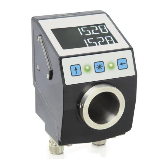
Absolute Position Indicator with RS485 / SIKONETZ5 interface
Brand:
Siko
| Category:
Touch Panel
| Size: 1 MB
Table of Contents
Table of Contents
2
1 General Informaton
5
Dokumentation
5
Definitions
5
2 Intended Use
5
Switching on the Supply Voltage
6
3 Display and Control Keys
6
General
6
LCD Display
6
Extended Display Range
7
LED Display
7
Keys
7
4 Functional Description
8
Operating Modes
8
Position-Bound Operating Modes
9
Positioning
9
Loop Positioning
10
Alpha-Numeric Display Operating Mode
11
Battery Buffering
12
Parameterization of the Position Indicator
12
Manual Parameterization
12
Starting Parameterization
12
Value Input
12
Value Selection
13
Adjustable Parameters
13
Parameterization Via Interface
13
Warnings / Errors
13
Warnings
13
Errors
14
System Commands
14
Calibration
14
Restore Factory Settings
15
Read Error Memory
15
Diagnosis of Bus Communication
15
General Communication
16
Data Scan
18
Telegram Scan
19
5 Overview of Parameters
19
6 Communication Via SIKONETZ 5
21
Interface
21
Data Exchange
21
Telegram Setup
22
Command
22
Node Address
22
Parameter Address
22
Control Word
23
Status Word
23
Data
24
Check Sum
24
Synchronization
25
Error Telegram
25
SIKONETZ5 Error Codes
25
Communication Errors
26
Communication Monitoring
26
Bus-Timeout
26
Programming Interlock
26
Auto-ID
27
Parameter Description
29
00H: Node Address
29
01H: Baud Rate
29
02H: Bus Timeout
29
03H: Response Parameter to a Set Point Write Access
30
04H: Keys Enable Time: Configuration Start Delay
30
05H: Key Function Enable1: Calibration Enable
30
06H: LED Flashing
31
07H: LED3 (Green Right)
31
08H: LED2 (Red Left)
31
09H: LED1 (Green Left)
32
0Ah: Decimal Places
32
0Bh: Display Divisor (ADI)
32
0Ch: Direction Indicators (CW, CCW)
33
0Dh: Display Orientation
33
0Eh: Configuration Programming Mode
33
1Bh: Counting Direction
34
1Ch: Resolution Per Revolution
34
1Eh: Offset Value
35
1Fh: Calibration Value
35
20H: Target Window1 (Near Field)
35
21H: Positioning Type (Loop Type)
36
22H: Loop Length
36
28H: Operating Mode
36
30H: Display in the 2
37
Row
37
31H: Target Window2 (Extended)
37
32H: Target Window2 Visualization
37
33H: Application of the Display Divisor (ADI Application)
38
34H: Formation of the Differential Value
38
35H: Key Function Enable2: Incremental Measurement Enable
39
39H: LED4 (Red Right)
39
3Ah: LCD Backlight Flashing
39
3Bh: LCD Backlight White
40
3Ch: LCD Backlight Red
40
3Dh: Key Function Enable3: Configuration Enable Via Keyboard
40
3Eh: Acknowledgement Settings
41
3Fh: Display Factor
41
63H: Battery Voltage
42
65H: Device Identification
42
67H: Software Version
43
80H: Number of Errors
43
81H until 8Ah: Errors
43
96H: Input Errors
44
A0H: System Commands
44
A7H: Calibration Travel
45
A8H: Programming Mode
45
Aah: Freeze Actual Value
45
C5H: ADC Values of the Sensor
46
Cfh: Period Counter
46
D0H: Response Delay
46
D2H: Auto-ID Assignment
47
Fah: Status Word
47
Fbh: Set Point1
47
Fch: Differential Value
48
Fdh: Error Telegram
48
Feh: Position Value
48
Ffh: Set Point2
49
7 Communication Via Service Standard Protocol
49
General
49
Error Number Encoding
49
Service Protocol Commands List
49
Siko AP10 User Manual (42 pages)
Absolute PositioAbsolute Position Indicator with IO-Link interfacen Indicator with interface
Brand:
Siko
| Category:
Measuring Instruments
| Size: 0 MB
Table of Contents
Table of Contents
2
General Information
5
Documentation
5
History
5
Definitions
5
Intended Use
5
Switching on the Operating Voltage
6
Display and Control Elements
6
LCD Display
7
Extended Display Range
7
LED Display
7
Device Status
7
Control Keys
8
Key Lock and Enable Time
8
Functional Description
8
Operating Modes
8
Absolute Position Operating Mode
8
Positioning
8
Loop Positioning
9
Controlword in Absolute Position Operating Mode
10
Statusword in Absolute Position Operating Mode
11
Alpha-Numeric Display Operating Mode
12
Controlword: Alpha-Numeric Display
12
Statusword: Alpha-Numeric Display
13
Battery Buffering
14
Parameterization of the Position Indicator
14
Manual Parameterization
14
Starting Parameterization
14
Value Input
15
Value Selection
15
Overview of the Operating Menu
16
Changeable Parameters" Menu
16
Positioning
17
Visualization
17
LED Function
17
Device Options
18
Parameterization Via Interface
18
Calibration
18
Additional Functions
18
Device Data
18
Restore Factory Settings
19
Warnings / Errors
19
Warnings
19
Errors
19
Corrective Actions
20
Parameter
20
Process Data
20
Controlword
20
Statusword
21
Targetvalue
21
Actualvalue
21
Displaydata
22
Targetvalueleft
22
Positioning
23
Resolution
23
Decimalplaces
23
Displaydivisor
24
Countingdirection
24
Calibrationvalue
25
Targetwindow
25
Looptype
26
Looplength
26
Visualization
27
Displayorientation
27
Leds
27
Ledmode
27
Led1Greenmode
28
Led2Greenmode
28
Led1Redmode
29
Led2Redmode
29
Activeledsflashing
30
Device Options
30
Keyenabletime
30
Keycalibration
31
Keyincremental
31
Operatingmode
32
Sensortype
32
Pinchange
33
Loaddefault
33
Code
33
IO-Link
34
Process Data Input / Output
34
Process Data in Absolute Position Operating Mode
35
Process Data Output (Master Device)
35
Process Data Input (Device Master)
36
Process Data in Alphanumeric Display Operating Mode
37
Process Data Output (Master Device)
37
Process Data Input (Device Master)
38
Directory of Objects
39
IO-Link Specific Objects
39
Systemcommands
40
Deviceaccesslocks
40
Eventcodes
40
Errorcodes
41
Block Diagram
41
Advertisement
Siko AP10 Installation Instructions Manual (44 pages)
Absolute / Electronic Position Indicator
Brand:
Siko
| Category:
Measuring Instruments
| Size: 4 MB
Table of Contents
Deutsch
2
Table of Contents
2
1 Dokumentation
3
2 Sicherheitshinweise
3
Bestimmungsgemäße Verwendung
3
Kennzeichnung von Gefahren und Hinweisen
3
Zielgruppe
4
Grundlegende Sicherheitshinweise
4
3 Identifikation
5
4 Installation
5
Mechanische Montage
6
Elektrische Installation
8
Anschlusskonzept (RS485, Canopen)
8
Anschlusskonzept (IO-Link)
11
5 Inbetriebnahme
13
Kalibrierung
15
6 Batteriewechsel
16
Art, Funktion und Lebensdauer der Batterie
16
Betriebszustand
16
Austausch der Batterieeinheit
17
Störung nach Batteriewechsel
18
7 Transport, Lagerung, Wartung und Entsorgung
18
8 Zubehör Anschluss-Stecker
19
Gegenstecker M8 Gerade Inkl. Kabel
19
Gegenstecker M8 Gerade
19
Gegenstecker M8 BUS-Abschluss (RS485, Canopen)
20
9 Technische Daten
20
English
23
1 Documentation
24
2 Safety Information
24
Intended Use
24
Identification of Dangers and Notes
24
Target Group
25
Basic Safety Information
25
3 Identification
26
4 Installation
26
Mechanical Mounting
27
Electrical Installation
28
Connection Concept (RS485, Canopen)
29
Connection Concept (IO-Link)
32
5 Commissioning
33
Calibration
36
6 Battery Change
36
Battery, Function and Service Life
37
Operating States
37
Changing the Battery Unit
37
Faults after Battery Change
38
7 Transport, Storage, Maintenance and Disposal
38
8 Accessory Connector
39
Mating Connector M8 Straight Inclusive Cable
39
Straight Matting Connector M8
39
Mating Connector M8 Bus Terminator (RS485, Canopen)
40
9 Technical Data
40
Advertisement
Related Products
Siko AP04
Siko AP10S
Siko AP05
Siko AP20
Siko AP20S
Siko AP10T
Siko AP10S-0023
Siko AP09
Siko AP04S
Siko AG02
Siko Categories
Media Converter
Accessories
Monitor
Measuring Instruments
Controller
More Siko Manuals
Login
Sign In
OR
Sign in with Facebook
Sign in with Google
Upload manual
Upload from disk
Upload from URL