Sign In
Upload
Manuals
Brands
Siemens Manuals
Engine
SIMOTICS FD 1MN1
Siemens SIMOTICS FD 1MN1 Manuals
Manuals and User Guides for Siemens SIMOTICS FD 1MN1. We have
1
Siemens SIMOTICS FD 1MN1 manual available for free PDF download: Operating Instructions Manual
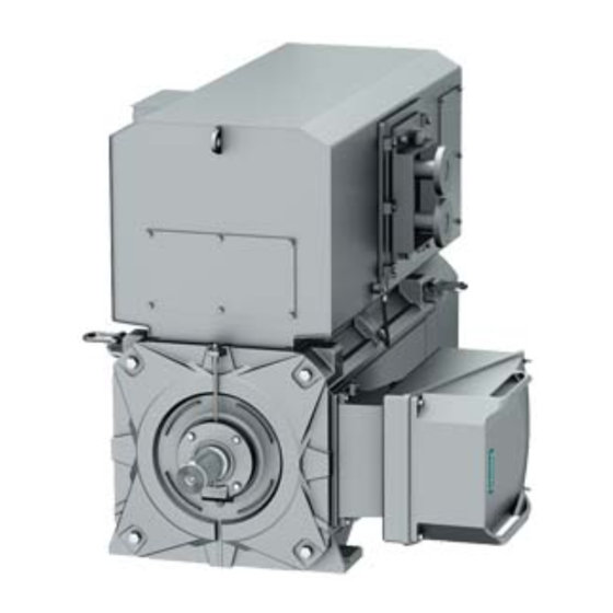
Siemens SIMOTICS FD 1MN1 Operating Instructions Manual (194 pages)
Low-voltage motor
Brand:
Siemens
| Category:
Engine
| Size: 4.49 MB
Table of Contents
Table of Contents
5
1 Introduction
13
About These Instructions
13
Compiling Personal Documents
13
2 Safety Information
15
The 5 Safety Rules
15
Qualified Personnel
15
Safe Handling
16
For Use in Hazardous Zone 2 or Zone 22
17
Electrostatic Sensitive Devices
18
Processes that Generate High Levels of Electrostatic Charge
19
Interference Immunity
20
Interference Voltages When Operating the Converter
20
Electromagnetic Fields When Operating Electrical Power Engineering Installations
20
3 Description
21
Table 3-1 Machine Design
21
Table 3-2 Machine Design with Type of Protection Ex Ec
22
Table 3-3 Data on the Rating Plate
25
Table 3-4 Rolling-Contact Bearing Variants
27
4 Preparations for Use
29
Safety-Related Aspects to Consider When Configuring the Plant
29
Observing the Operating Mode
29
Ensuring Cooling
29
Space Requirement
30
Table 4-1 Space Required for the Separately-Driven Fan
30
Table 4-2 Space Required for Removing/Installing the Water Cooler
30
Configuration of the Cooling Circuit and Coolant Supply
31
Material Selection for the Cooling Circuit
31
Pressures and Differential Pressures in the Cooling Circuit
32
Components and Materials of the Cooling Circuit
32
Table 4-3 Materials and Components of a Cooling Circuit
32
Potential Equalization on the Cooling Circuit Components
33
Coolant Specification
33
General Coolant Requirements
33
Table 4-4 Substances that Can Destroy the Cooling System
34
Coolant Specification
35
Inhibitors, Anti-Freeze, Biocides
36
Table 4-5 Overview and Application of Coolant Additives
36
Cooling Capacity Derating
37
Interlock Circuit for the Cooling-Water Monitoring
38
Interlock Circuit for the External Fan Motor
38
Thermal Motor Protection
38
Thermal Motor Protection Using PTC Thermistors (Option)
39
Interlock Circuit for the Automatic Regreasing System (Option)
39
Interlock Circuit for Anti-Condensation Heating
39
IM B5 Type of Construction with Support Foot
40
Noise Emissions
40
Rotational Speed Limit Values
40
Complying with Speed-Torque Curve
41
Voltage and Frequency Fluctuations During Line Operation
41
Phase Synchronization During Supply System Switching
41
System-Inherent Frequencies
41
Torsional Load of the Drive Train
42
Transport
42
Safety Instructions for Transport
42
Checking the Delivery
44
Securing the Rotor
45
Lifting and Transporting the Machine
47
Storage
47
Storing the Machine
47
Protecting the Cooling Water Circuit During Storage
50
Protection against Corrosion
51
Converter Operation
51
Converter Operation of Explosion-Proof Machines
51
Supply Line Configuration
52
Converter Input Voltage
52
Reducing Bearing Currents
53
Insulated Bearings When Operating the Converter
54
Converter Operation on a Grounded Network
55
5 Assembly
57
Safety Instructions for Mounting
57
Preparations for Installation
58
Requirements for Installation
58
Insulation Resistance and Polarization Index
59
Testing the Insulation Resistance and Polarization Index
59
Table 5-1 Stator Winding Insulation Resistance at 40° C
60
Prepare the Mating Faces (IM B3)
62
Prepare the Mating Face for a Flange Connection
62
Prepare the Mating Face for Wall Mounting
62
Lift the Machine to Where It will be Installed, and Position It
62
Preconditions for Correct Alignment and Secure Attachment
62
Checking the Load Handling Attachments
63
Removing the Rotor Shipping Brace
63
Removing the Rotor Shipping Brace from Machines in Vertical Type
63
Removing Anti-Corrosion Protection
64
Mounting the Output Elements
64
Lifting and Transportation
66
Putting the Machine down
67
Draining Condensation
68
Roughly Aligning the Machine
69
Installing the Machine
70
Preconditions for Smooth, Vibration-Free Operation
70
Aligning the Machine to the Driven Machine and Mounting (IM B3 / IM B35)
70
Table 5-2 Permissible Deviations for Aligning the Machine with Flexible Coupling
71
Aligning the Machine to the Driven Machine and Attaching It to It (IM B5)
72
Aligning the Machine to the Driven Machine and Attaching It to It (IM V1, IM V10)
73
Axial and Radial Forces
73
Connecting the Cooling Water Supply
74
6 Electrical Connection
77
Safety Instructions for the Electrical Connection
77
Basic Rules
77
Terminal Box
78
Terminal Box 1XB1621
79
Terminal Box 1XB1631
79
Terminal Box 1XB7730
80
Terminal Box 1XB7731
81
Terminal Box 1XB7740
81
Terminal Box 1XB7750
82
Rotating the Terminal Box
82
Mounting/Removing the Terminal Box
85
Preparation
86
Terminal Designation
86
Selecting Cables
86
Table 6-1 Terminal Designations Using the 1U1-1 as an Example
86
Connecting the Grounding Conductor
87
Connect Metal Shield in the Terminal Box
88
Connection Without Terminal Box
88
Connecting the Machine for a Specific Direction of Rotation
89
Undrilled Entry Plate
89
Inserting and Routing the Cables
90
Bringing Cables into the Terminal Box 1XB
90
Table 6-2 Connection Technology (with Cable Lug / Connection Without Cable Lug)
90
Bringing Cables into the Terminal Box 1XB
92
Certified Cable Entries, Thread Adapters and Sealing Plugs
92
Laying Cables
93
Connecting Cables with Cable Lugs
93
Connecting Cables Without Cable Lugs
94
Use of Aluminum Conductors
96
Using Single-Stranded Cables
97
Internal Equipotential Bonding
97
Stepless Mating Face for the Seal in the Terminal Box Cover
97
Minimum Air Clearances
98
Finishing Connection Work
98
Connecting the Auxiliary Circuits
99
Selecting Cables
99
Bringing Cables into the Auxiliary Terminal Box and Routing Them
99
Intrinsically Safe Circuits for Sensors or Probes
100
Connect Metal Shield in the Terminal Box
100
Connecting an External Fan Motor
100
Connecting Temperature Monitoring for the Stator Winding
101
Terminating the Connection Work (Auxiliary Circuit)
102
7 Start-Up
103
Checks to be Carried out Prior to Commissioning
103
Converter Operation
105
Measuring the Insulation Resistance before Commissioning
105
Greasing the Roller Bearings Prior to Commissioning
106
Setting the Automatic Regreasing System
107
Commissioning an External Fan
107
Setpoint Values for Monitoring the Bearing Temperature
108
Set Values for Monitoring the Winding Temperature
109
Test Run
109
Switching off
111
Setting the Motor Parameters at the Converter
111
Selecting the Motor Type and Motor Data in the STARTER Program
111
Commissioning at the SINAMICS S/G Converter Using the AOP30
114
Commissioning at the SINAMICS G120P Inverter Using the IOP
117
8 Operation
119
Safety Instructions for Operation
119
Operation in Hazardous Areas of Zone 2
121
Switching on the Machine
122
Regreasing Roller Bearings
122
Stoppages
122
Avoidance of Frost and Corrosion Damage in the Cooling System
123
Avoidance of Condensation or Formation of Condensation Within the Machine
123
Avoidance of Damage to Roller Bearings During Stoppages
124
Measurement of the Insulation Resistance after an Extended Stoppage
124
Decommissioning the Machine
125
Switch off the External Fan
125
Switching off the Water-Cooling System
125
Re-Commissioning the Machine
125
Switching on Again after an Emergency Switching-Off
125
Faults
126
Inspections in the Event of Faults
126
Electrical Faults
127
Mechanical Faults
127
Air-To-Water Cooler Faults
128
Faults at the External Fan
129
Roller Bearing Faults
130
9 Maintenance
131
Inspection and Maintenance
131
Safety Instructions for Inspection and Maintenance
131
Measuring the Insulation Resistance During the Course of Maintenance Work
133
Inspections in the Event of Faults
133
First Service after Installation or Repair
134
General Inspection
134
Inspection of the Cooling System
135
Servicing and Maintaining the Anti-Condensation Heating
135
Assessing the Roller Bearings
135
Roller Bearings with Automatic Regreasing System
136
Regreasing Intervals and Types of Grease for Operating Roller Bearings
136
Sealing the Rolling-Contact Bearings ("Increased Degree of Protection" Option)
140
Cleaning the Air-To-Water Heat Exchanger
140
Servicing the External Fan
140
Touch up any Damaged Paintwork
141
Repainting
141
Maintaining Terminal Boxes
142
Corrective Maintenance
143
Prepare Servicing Work
143
Screws with Precote Coating
144
External Fan
144
Replacing the External Fan
144
External Fan Unit
145
Adjusting the External Fan
145
Roller-Contact Bearings
147
Removing Roller Bearing
147
Remove V Ring
147
Removing the Labyrinth Sealing Ring
148
Installing Roller Bearings
149
Install the V Ring
150
Installing the V Ring ("Increased Degree of Protection" Option)
151
Installing the Labyrinth Sealing Ring
151
Top Enclosure
152
Removing and Installing the Air-To-Water-Cooler
152
Removing the Top Enclosure
153
Mounting the Top Enclosure
155
Seal the Motor
156
10 Spare Parts
157
Ordering Data
157
Ordering Spare Parts Via the Internet
158
Anti-Condensation Heating
159
Housing, Stators and Rotors
160
Top Enclosure
162
Roller Bearing Cartridge at the Drive and Non-Drive End
163
Roller Bearing Cartridge at the Drive and Non-Drive End
164
Terminal Box 1XB1621
165
Terminal Box 1XB1631
167
Terminal Box 1XB7730
168
Terminal Box 1XB7731
169
Terminal Box 1XB7740
170
Terminal Box 1XB7750
171
Auxiliary Terminal Box 1XB9014
172
Auxiliary Terminal Box 1XB9015
173
1XB9016 Auxiliary Terminal Box
174
Auxiliary Terminal Box 1XB302
175
11 Disposal
177
Rohs - Restricting the Use of Certain Hazardous Substances
177
Information According to Article 33 of the REACH Regulation
177
Preparing for Disassembly
178
Dismantling the Machine
178
Disposal of Components
178
Service and Support
181
Technical Data and Drawings
183
Tightening Torques for Screw and Bolt Connections
183
Quality Documents
185
Index
187
Advertisement
Advertisement
Related Products
Siemens SIMOTICS FD 1MH1
Siemens SIMOTICS FD 1MQ1
Siemens SIMOTICS FD 1LL1
Siemens SIMOTICS FD 1MM1 Series
Siemens SIMOTICS FD 1LH1
Siemens SIMOTICS FD 1LN1
Siemens SIMOTICS FD 1LM1
Siemens SIMOTICS FD 1LP1
Siemens SIMOTICS FD 1LQ1
Siemens SIMOTICS XP 1LA5
Siemens Categories
Industrial Equipment
Controller
Control Unit
Oven
Washer
More Siemens Manuals
Login
Sign In
OR
Sign in with Facebook
Sign in with Google
Upload manual
Upload from disk
Upload from URL