Sign In
Upload
Manuals
Brands
Siemens Manuals
Cell Phone Accessories
AC75
Siemens AC75 Manuals
Manuals and User Guides for Siemens AC75. We have
2
Siemens AC75 manuals available for free PDF download: User Manual, Hardware Interface Description
Siemens AC75 User Manual (123 pages)
Siemens Cell Phone Accessories User Manual
Brand:
Siemens
| Category:
Cell Phone Accessories
| Size: 6.35 MB
Table of Contents
Table of Contents
3
1 Preface
11
2 Overview
12
Related Documents
12
Figure 1: Overview
12
Terms and Abbreviations
13
3 Installation
15
System Requirements
15
Installation CD for AC65/AC75 and XT65/XT75
16
Installation CD for TC65
17
Components
18
Module Exchange Suite
18
Wtk
18
Sdk / Jdk
19
Netbeans IDE 5.0
19
Netbeans IDE 5.5.1
19
Eclipse 3.1.2 IDE and Eclipse ME Plugin 1.5.X
20
Eclipse 3.2.2 IDE and Eclipse ME Plugin 1.5.5 or 1.6.8
20
GPS Evaluation Software
21
Integrated Documentation Suite (IDS)
21
Set up Java Development Environment with Eclipse IDE (Quick Start-Up)
22
Figure 2: Installation of Eclipse ME-Plugin 1.2.3: Dialog Box Feature Updates
22
Figure 3: Installation of Eclipse ME-Plugin 1.2.3: Dialog Box Updates Sites to Visit
22
Figure 4: Installation of Eclipse ME-Plugin 1.2.3: Dialog Box Search Results
23
Figure 5: Installation of Eclipse ME-Plugin 1.2.3: Dialog Box Restart Eclipse
23
Siemens Mobility Toolkit Installation
24
Installing the Standard Development Toolkit
24
Installing the SMTK Environment
24
Installing Netbeans IDE 5.0 / Netbeans IDE 5.5.1
26
Installing Eclipse 3.0, Eclipse 3.1 or Eclipse 3.2
26
Installing Borland Jbuilder X, 2005 and 2006 Enterprise/Developer
27
Installing Module Exchange Suite (MES)
27
SMTK Uninstall
27
Upgrades
27
4 Software Platform
28
Software Architecture
28
Interfaces
29
ASC0 - Serial Device
29
General Purpose I/O
29
Dac/Adc
29
Asc1
29
Digital Audio Interface (DAI)
29
I2C/Spi
29
Gps
30
JVM Interfaces
31
IP Networking
31
Media
31
Other Interfaces
31
Figure 6: Interface Configuration
31
Data Flow of a Java Application Running on the Module
32
Figure 7: Data Flow of a Java Application Running on the Module
32
Handling Interfaces and Data Service Resources
33
Module States
33
State 1: Default - no Java Running
33
Figure 8: Module State 1
33
State 2: no Java Running, General Purpose I/O and I2C/SPI
34
State 4: Default - Java Application Active
34
State 5: Java Application Active, General Purpose I/O and I2C/SPI34
34
Figure 9: Module State 2
34
Figure 10: Module State 4
34
Figure 11: Module State 5
34
Module State Transitions
35
Figure 12: Module State Transition Diagram
35
5 Maintenance
36
IP Service
36
Remote SIM Access
37
Power Saving
37
Charging
38
Airplane Mode
38
Alarm
38
Shutdown
39
Automatic Shutdown
39
Manual Shutdown
39
Restart after Switch off
39
Watchdog
39
Special at Command Set for Java Applications
40
Switching from Data Mode to Command Mode
40
Mode Indication after Midlet Startup
40
Long Responses
40
Configuration of Serial Interface
40
Java Commands
41
Autoexec Function
41
System out
41
Serial Interfaces
41
File
42
Udp
42
Gpio
42
Restrictions
42
Flash File System
42
Memory
42
Performance
43
Java
43
Figure 13: Test Case for Measuring Java Command Execution Throughput
43
Pin I/O
44
Data Rates on RS-232 API
44
Figure 14: Test Case for Measuring Java Midlet Performance and Handling Pin-IO
44
Figure 15: Scenario for Testing Data Rates on ASC1
45
Figure 16: Scenario for Testing Data Rates on ASC1 with a Voice Call in Parallel
45
Plain Serial Interface
45
Scenarios with GPRS/EGDE Connection
45
Voice Call in Parallel
45
Table 1: GPRS Upload Data Rate with Different Number of Timeslots, CS2
46
Table 2: GPRS Upload Data Rate with Different Number of Timeslots, CS4
46
Table 3: EDGE Upload Data Rate with Two Timeslots, CS5
46
Table 4: EDGE Upload Data Rate with Two Timeslots, CS9
46
Upload
46
Download
47
Figure 17: Scenario for Testing Data Rates on ASC1 with GPRS Data Upload
47
Figure 18: Scenario for Testing Data Rates on ASC1 with GPRS Data Download
47
Table 5: GPRS Download Data Rate with Different Number of Timeslots, CS2
48
Table 6: GPRS Download Data Rate with Different Number of Timeslots, CS4
48
Table 7: EDGE Download Data Rate with Different Number of Timeslots, CS5
48
Table 8: EDGE Download Data Rate with Different Number of Timeslots, CS9
48
System Time
49
6 Midlets
50
Midlet Documentation
50
Midlet Life Cycle
50
Table 9: a Typical Sequence of Midlet Execution
51
Hello World Midlet
52
7 File Transfer to Module
53
Module Exchange Suite
53
Windows Based
53
Command Line Based
53
Over the Air Provisioning
53
Security Issues
54
Module Exchange Suite
54
Otap
54
8 Over the Air Provisioning (OTAP)
55
Introduction to OTAP
55
OTAP Overview
55
Figure 19: OTAP Overview
55
OTAP Parameters
56
Table 10: Parameters and Keywords
56
Short Message Format
57
Java File Format
58
Procedures
59
Install/Update
59
Figure 20: OTAP: Install/Update Information Flow (Messages in Brackets Are Optional)
59
Delete
60
Figure 21: OTAP: Delete Information Flow (Messages in Brackets Are Optional)
60
Time out Values and Result Codes
61
Tips and Tricks for OTAP
61
OTAP Tracer
62
Security
62
How to
62
9 Compile and Run a Program Without a Java IDE
64
Build Results
64
Compile
65
Run on the Module with Manual Start
65
Run on the Module with Autostart
66
Switch on Autostart
66
Switch off Autostart
66
10 Compile and Run a Program with a Java IDE
67
Eclipse 3.1.2 (with ME Plugin 1.2.3)
67
Setup a New Project
67
Figure 22: Create New Eclipse Project: Create a J2ME MIDP Midlet Suite
67
Figure 23: Create New Eclipse Project: New J2ME Project
67
Figure 24: Create New Eclipse Project: Midlet Suite Properties
68
Figure 25: Create New Eclipse Project: Work Area with New Created Project
68
Figure 26: Create New Eclipse Project: Create a J2ME Midlet
69
Figure 27: Create New Eclipse Project: Create a New J2ME Midlet
69
Figure 28: Create New Eclipse Project: Edit some Java Commands
70
Figure 29: Create New Eclipse Project: Edit "Deployed" Path to Jar File
70
11 Debug Environment
72
Data Flow of a Java Application in the Debug Environment
72
Figure 30: Data Flow of a Java Application in the Debug Environment
72
Emulator
73
Java IDE
75
Netbeans IDE 5.0, Netbeans 5.5 or Netbeans 5.5.X
75
Switching Emulator to IMP-NG Emulator
76
Figure 31: Netbeans IDE 5.0 - Installed Emulators
76
Figure 32: Netbeans IDE 5.0 - Switching to IMP-NG Emulator
76
Templates
77
Figure 33: Netbeans IDE 5.0 - Selecting an IMP-NG Midlet Template
77
Examples
78
Figure 34: Netbeans IDE 5.0 - Selecting Sample Project "Hello World Sample
78
Figure 35: Netbeans IDE 5.0 - Confirmation of Sample Project "Hello World Sample
78
Compile and Run
79
Starting Debug Session Without Downloading Java Files
79
Figure 36: Netbeans IDE 5.0 - Add Emulator Option "-Noload
79
Displaying Java "System.out" in Netbeans IDE Window
80
Figure 37: Netbeans IDE 5.0 - Displaying Java "System.out" in Netbeans IDE Window
80
Eclipse 3.0 and Eclipse 3.1
81
Eclipse 3.0
81
Eclipse 3.1
81
Eclipse 3.2
81
Using Eclipse with ME Plugin up to Version 1.2.3
82
Figure 38: Eclipse - Display of Different Integrated Emulators
82
Using Eclipse with ME Plugin 1.5.X
83
Figure 39: Eclipse - J2ME Platform
83
Figure 40: Eclipse with ME Plugin 1.5.0 - Display of Different Integrated Emulators
84
Using Eclipse with ME Plugin 1.6.X
85
Figure 41: Eclipse with ME Plugin 1.5.0 - J2ME Platform
85
Import Example
86
Figure 42: Eclipse - Project Import
86
Figure 43: Eclipse - Example
86
Compile and Debug
87
Figure 44: Eclipse - Create Package
87
Figure 45: Eclipse - Configuration
88
Starting Debug Session Without Downloading Java Files
89
Figure 46: Eclipse - Configuration
89
Figure 47: Eclipse 3.2.X Me1.5.X and 1.6.X Select System Java Thread for Showing Breakpoint Line in Java Source
90
Borland Jbuilder X
91
Figure 48: Jbuilder X - JDK Settings
91
Figure 49: Jbuilder X - Siemens Library
91
Examples
92
Figure 50: Jbuilder X - Sample Projects
92
Figure 51: Jbuilder X - Starting the Debugging Session
92
Figure 52: Jbuilder X - Edit Project Properties for Starting the Emulator
93
Figure 53: Jbuilder - Runtime Configuration
93
Starting Debug Session Without Downloading Java Files
93
Borland Jbuilder 2005 and Jbuilder 2006 Enterprise/Developer
94
Figure 54: Jbuilder 2006 Enterprise/Developer - JDK Settings
94
Figure 55: Jbuilder 2006 Enterprise/Developer - Siemens Library
94
Examples
95
Breakpoints
95
Figure 56: Jbuilder 2006 Enterprise/Developer - Sample Projects
95
Switching Java "System.out" to IDE Debug Window
96
Figure 57: Emulator Configuration File "Switching Java System.out to Serial Port
96
Important Information for Java Debugging on Windows Vista
97
Figure 58: Using Windows Vista: Set Eclipse.exe Perament to "Run as Administrator
97
12 Java Security
98
Secure Data Transfer
98
Figure 59: Mode 1 - Customer Root Certificate Does Not Exist
99
Figure 60: Mode 2 - Server Certificate and Certificate into Module Are Identical
99
Create a Secure Data Transfer Environment Step by Step
100
Figure 61: Mode 2 - Server Certificate and Self Signed Root Certificate in Module Form a Chain
100
Execution Control
103
Change to Secured Mode Concept
104
Figure 62: Insert Customer Root Certificate
104
Concept for the Signing the Java Midlet
105
Figure 63: Prepare Midlet for Secured Mode
105
Application and Data Protection
106
Structure and Description of the Java Security Commands
106
Structure of the Java Security Commands
107
Build Java Security Command
108
Figure 64: Build Java Security Command
108
Send Java Security Command to the Module
109
Create a Java Security Environment Step by Step
110
Create Key Store
110
Export X.509 Root Certificate
110
Create Java Security Commands
110
Sign a Midlet
112
Attention
112
13 Java Tutorial
113
Using the at Command API
113
Class Atcommand
113
Instantiation with or Without CSD Support
113
Sending an at Command to the Device, the Send() Method
114
Data Connections
115
Synchronization
117
Atcommandresponselistener Interface
117
Non-Blocking Atcommand.send() Method
117
Atcommandlistener Interface
118
Atevents
118
Implementation
119
Registering a Listener with an Atcommand Instance
120
Programming the Midlet
121
Threads
121
Example
121
14 Differences to the TC45
123
Advertisement
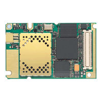
Siemens AC75 Hardware Interface Description (120 pages)
Cellular Engine
Brand:
Siemens
| Category:
Control Unit
| Size: 2.98 MB
Table of Contents
Table of Contents
3
Document History
7
1 Introduction
8
Related Documents
8
Terms and Abbreviations
9
Type Approval
12
Table 1: Directives
12
Table 2: Standards of North American Type Approval
12
Table 3: Standards of European Type Approval
13
Table 4: Requirements of Quality
13
Safety Precautions
14
2 Product Concept
16
Key Features at a Glance
16
AC75 System Overview
19
Figure 1: AC75 System Overview
19
Circuit Concept
20
Figure 2: AC75 Block Diagram
20
3 Application Interface
21
Operating Modes
22
Table 5: Overview of Operating Modes
22
Power Supply
24
Minimizing Power Losses
24
Monitoring Power Supply by at Command
25
Measuring the Supply Voltage
25
Batt
25
Figure 3: Power Supply Limits During Transmit Burst
25
Figure 4: Position of the Reference Points BATT+ and GND
25
Power-Up / Power-Down Scenarios
26
Turn on AC75
26
Turn on AC75 Using Ignition Line IGT
26
Figure 5: Power-On with Operating Voltage at BATT+ Applied before Activating IGT
27
Figure 6: Power-On with IGT Held Low before Switching on Operating Voltage at BATT
28
Configuring the IGT Line for Use as ON/OFF Switch
29
Figure 7: Timing of IGT if Used as ON/OFF Switch
29
Turn on AC75 Using the VCHARGE Signal
30
Reset AC75 Via AT+CFUN Command
30
Reset or Turn off AC75 in Case of Emergency
31
Using EMERG_RST Signal to Reset Application(S) or External Device(S)
31
Signal States after Startup
32
Table 6: Signal States
32
Turn off AC75
34
Turn off AC75 Using at Command
34
Leakage Current in Power-Down Mode
35
Figure 8: Signal States During Turn-Off Procedure
35
Turn On/Off AC75 Applications with Integrated USB
36
Automatic Shutdown
37
Thermal Shutdown
37
Deferred Shutdown at Extreme Temperature Conditions
38
Monitoring the Board Temperature of AC75
38
Undervoltage Shutdown if Battery NTC Is Present
38
Table 7: Temperature Dependent Behavior
38
Undervoltage Shutdown if no Battery NTC Is Present
39
Overvoltage Shutdown
39
Automatic EGPRS/GPRS Multislot Class Change
40
Charging Control
41
Hardware Requirements
41
Software Requirements
41
Battery Pack Requirements
42
Figure 9: Battery Pack Circuit Diagram
42
Batteries Recommended for Use with AC75
43
Table 8: Specifications of Battery Packs Suitable for Use with AC75
43
Charger Requirements
44
Implemented Charging Technique
44
Operating Modes During Charging
45
Table 9: at Commands Available in Charge-Only Mode
45
Table 10: Comparison Charge-Only and Charge Mode
46
Power Saving
47
Network Dependency of SLEEP Modes
47
Figure 10: Power Saving and Paging
47
Timing of the Ctsx Signal in CYCLIC SLEEP Mode 7
48
Timing of the Rtsx Signal in CYCLIC SLEEP Mode 9
48
Figure 11: Timing of Ctsx Signal (if CFUN= 7)
48
Figure 12: Timing of Rtsx Signal (if CFUN = 9)
48
Summary of State Transitions (Except SLEEP Mode)
49
Table 11: State Transitions of AC75 (Except SLEEP Mode)
49
RTC Backup
50
Figure 13: RTC Supply from Capacitor
50
Figure 14: RTC Supply from Rechargeable Battery
50
Figure 15: RTC Supply from Non-Chargeable Battery
50
SIM Interface
51
Table 12: Signals of the SIM Interface (Board-To-Board Connector)
51
Installation Advice
52
Serial Interface ASC0
53
Figure 16: Serial Interface ASC0
53
Table 13: DCE-DTE Wiring of ASC0
54
Serial Interface ASC1
55
Table 14: DCE-DTE Wiring of ASC1
55
Figure 17: Serial Interface ASC1
55
USB Interface
56
Figure 18: USB Circuit
56
Installing the USB Modem Driver
57
I 2 C Interface
59
Figure 19: I2C Interface Connected to VCC of Application
59
Figure 20: I2C Interface Connected to VEXT Line of AC75
60
SPI Interface
61
Figure 21: SPI Interface
61
Figure 22: Characteristics of SPI Modes
62
Audio Interfaces
63
Figure 23: Audio Block Diagram
63
Microphone Circuit
64
Speech Processing
64
Figure 24: Single Ended Microphone Input
65
Single-Ended Microphone Input
65
Differential Microphone Input
66
Figure 25: Differential Microphone Input
66
Figure 26: Line Input Configuration with Opamp
67
Line Input Configuration with Opamp
67
Figure 27: Differential Loudspeaker Configuration
68
Loudspeaker Circuit
68
Digital Audio Interface (DAI)
69
Table 15: Configuration Combinations for the PCM Interface
69
Figure 28: Master PCM Interface Application
70
Master Mode
70
Table 16: Overview of DAI Pin Functions
70
Figure 29: Short Frame PCM Timing
71
Figure 30: Long Frame PCM Timing
71
Figure 31: Slave PCM Interface Application
72
Slave Mode
72
Figure 32: Slave PCM Timing, Short Frame Selected
73
Figure 33: Slave PCM Timing, Long Frame Selected
73
GPIO Interface
74
Using the GPIO10 Pin as Pulse Counter
74
Control Signals
75
Synchronization Signal
75
Figure 34: SYNC Signal During Transmit Burst
75
Using the SYNC Pin to Control a Status LED
76
Figure 35: LED Circuit (Example)
76
Behavior of the RING0 Line (ASC0 Interface Only)
77
PWR_IND Signal
77
Figure 36: Incoming Voice/Fax/Data Call
77
Figure 37: URC Transmission
77
4 Antenna Interface
78
Table 17: Return Loss in the Active Band
78
Antenna Diagnostic
79
Table 18: Values of the AT^SAD Parameter <Diag> and Their Meaning
79
Figure 38: Resistor Measurement Used for Antenna Detection
79
Antenna Connector
80
Table 19: Product Specifications of Rosenberger SMP Connector
80
Figure 39: Datasheet of Rosenberger SMP MIL-Std 348-A Connector
81
5 Electrical, Reliability and Radio Characteristics
82
Absolute Maximum Ratings
82
Table 20: Absolute Maximum Ratings
82
Operating Temperatures
83
Table 21: Board Temperature
83
Table 22: Ambient Temperature According to IEC 60068-2 (Without Forced Air Circulation)
83
Table 23: Charging Temperature
83
Storage Conditions
84
Table 24: Storage Conditions
84
Reliability Characteristics
85
Table 25: Summary of Reliability Test Conditions
85
Pin Assignment and Signal Description
86
Figure 40: Pin Assignment (Component Side of AC75)
86
Table 26: Signal Description
87
Power Supply Ratings
93
Table 27: Power Supply Ratings
93
Table 28: Current Consumption During Tx Burst for GSM 850Mhz and GSM 900Mhz
94
Table 29: Current Consumption During Tx Burst for GSM 1800Mhz and GSM 1900Mhz
95
Electrical Characteristics of the Voiceband Part
96
Setting Audio Parameters by at Commands
96
Table 30: Audio Parameters Adjustable by at Command
96
Audio Programming Model
97
Figure 41: Audio Programming Model
97
Characteristics of Audio Modes
98
Table 31: Voiceband Characteristics (Typical)
98
Voiceband Receive Path
99
Table 32: Voiceband Receive Path
99
Voiceband Transmit Path
100
Table 33: Voiceband Transmit Path
100
Air Interface
101
Table 34: Air Interface
101
Electrostatic Discharge
102
Table 35: Measured Electrostatic Values
102
6 Mechanics
103
Mechanical Dimensions of AC75
103
Figure 42: AC75 - Top View
103
Figure 43: Dimensions of AC75
104
Mounting AC75 to the Application Platform
105
Board-To-Board Application Connector
106
Table 36: Technical Specifications of Molex Board-To-Board Connector
106
Figure 44: Molex Board-To-Board Connector 52991-0808 on AC75
107
Figure 45: Mating Board-To-Board Connector 53748-0808 on Application
108
7 Sample Application
109
Figure 46: AC75 Sample Application for Java
110
8 Reference Approval
111
Reference Equipment for Type Approval
111
Figure 47: Reference Equipment for Type Approval
111
Compliance with FCC Rules and Regulations
112
9 Appendix
113
List of Parts and Accessories
113
Table 37: List of Parts and Accessories
113
Table 38: Molex Sales Contacts (Subject to Change)
114
Fasteners and Fixings for Electronic Equipment
115
Fasteners from German Supplier ETTINGER Gmbh
115
Data Sheets of Recommended Batteries
118
Figure 48: Lithium Ion Battery from VARTA
119
Figure 49: VARTA Poliflex® Lithium Polymer Battery
120
Share and save
Advertisement
Related Products
Siemens AC65
Siemens AC43
Siemens AC45
Siemens AC165
Siemens ACUSON Cypress
Siemens AC5200
Siemens ACVATIX SQV..P Series
Siemens ACUSON S Series
Siemens SICHARGE CC AC22-MID
Siemens ACR12.3 1 Series
Siemens Categories
Controller
Control Unit
Industrial Equipment
Washer
Switch
More Siemens Manuals
Login
Sign In
OR
Sign in with Facebook
Sign in with Google
Upload manual
Upload from disk
Upload from URL