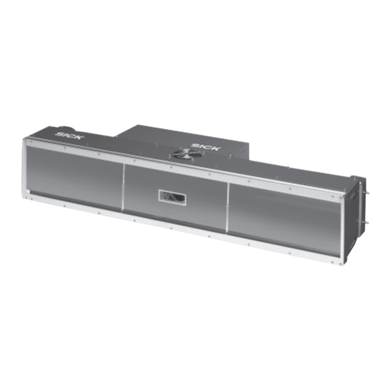
Sign In
Upload
Manuals
Brands
SICK Manuals
Security Camera
ICR890
SICK ICR890 Manuals
Manuals and User Guides for SICK ICR890. We have
3
SICK ICR890 manuals available for free PDF download: Operating Instructions Manual
SICK ICR890 Operating Instructions Manual (128 pages)
High-end CCD Camera System
Brand:
SICK
| Category:
Security Camera
| Size: 7 MB
Table of Contents
Table of Contents
5
Table of Contents
11
Notes on this Document
15
Information Content
15
Purpose
15
Tab. 1-1: Target Audience
15
Target Audience
15
Symbols Used
16
Safety Information
17
Authorized Users
17
Electrical Installation and the Replacement of System Components
17
Installation and Maintenance
17
Startup, Operation and Configuration
17
Intended Use
18
Electrical Installation Work
19
General Safety Precautions and Protection Measures
19
Installation Work
19
LED Radiation from the ICI890 Illumination
19
Radio Interferences
19
Quick Stop and Quick Start
20
Switch off the ICR890 System
20
Switch on the ICR890 System
20
Dispose of the Device after Decommissioning
21
Energy Requirements
21
Environmental Information
21
Product Description
23
Design
23
Device View
24
Included in Delivery
25
Tab. 3-1: Included in the Delivery of the ICR890 High-End CCD Camera System
25
Contents of the CD-ROM
26
Device Versions
26
General System Requirements
26
System Requirements
26
Tab. 3-2: System Component Versions
26
Installation Requirements
27
Tab. 3-3: General System Requirements (Standard Device)
27
Electrical Installation Requirements
28
Operation Requirements
28
Product Features and Functions (Overview)
29
Method of Operation
31
Reading Configuration
32
Focus Control
33
Illumination Control
33
Object Trigger Control
33
Increment Configuration
35
Position
35
Image Requirement
36
Code Configuration
37
Data Processing
37
Data Interfaces
39
Network
39
Output Format
39
Tab. 3-4: Data Interface Function
39
Digital Inputs
40
Digital Outputs
40
Indicators and Control Elements
41
User Interface
41
Leds of the ICD890 Camera
42
Tab. 3-5: LED Indications
42
Impacts on the Reading Quality
43
Installation
45
Installation Preparations
45
Layout Accessories
45
Layout the Components Which Are to be Installed
45
Overview of Installation Sequence
45
Selecting the Installation Location
46
Arrangement at the Conveyor System
47
Installing and Adjusting the Device
49
Installing the Deflection Mirror
50
Installing the ICI890 Illumination and the ICD890 Camera
50
External Sensors for Triggering
51
Installing External Components
51
Installing the Incremental Encoder
52
Installing the MLG Light Grid
52
Installing the MSC800 Controller
52
Removing the Device
52
Chapter 4 Installation
48
Electrical Installation
53
Overview of Installation Sequence
53
Electrical Installation of the ICR890 System (Without MSC800)
54
Electrical Installation Preparation
54
Tab. 5-1: ICR890 System (Stand-Alone Device) Without MSC800: Overview of the ICD890 Camera Connections Which Have to be Established
55
Electrical Installation of the ICR890 System with MSC800 (Single-Side Reading)
56
Tab. 5-2: ICR890 System (Stand-Alone Device) with MSC800: Overview of the ICD890 Camera Connections Which Have to be Established
56
Tab. 5-3: ICR890 System (Stand-Alone Device) with MSC800: Overview of the MSC800 Connections Which Have to be Established
57
Electrical Installation of the ICR890 System with MSC800 (Multi-Side Reading)
58
Tab. 5-4: ICR890 System with MSC800 (Multi-Side Reading): Overview of the ICD890 Camera Connections Which Have to be Established
58
Tab. 5-5: ICR890 System with MSC800 (Multi-Side Reading): Overview of the MSC800 Connections Which Have to be Established
59
Tab. 5-6: ICR890 System with MSC800 (Multi-Side Reading): Overview of the Vms4Xx/5Xx Connections Which Have to be Established
59
Electrical Connections and Cables
60
Electrical Connections of the ICD890 Camera
60
Electrical Connections of the ICI890 Illumination
61
Tab. 5-7: ICD890 Camera: Function of the Electrical Connections
61
Tab. 5-8: ICI890 Illumination: Function of the Electrical Connections
61
Electrical Connections of the MSC800 (Overview)
62
Tab. 5-9: MSC800-0000 Logic Controller: Function of the Electrical Connections (Overview)
62
Assembled Cables (Overview)
63
Tab. 5-10: Cables for Connecting the ICR890 System
63
Connecting the Power Supply Cable and the ICI890 Illumination Control Line
64
Performing Electrical Installation
64
Power Supply of the ICR890 System
64
Data Interfaces HOST/AUX
65
Tab. 5-11: Maximum Cable Lengths between ICR890 and the Host
65
Data Interface CAN 1-IN/OUT
66
Tab. 5-12: CAN Bus: Maximum Cable Lengths, Depending on the Data Transfer Rate
66
Tab. 5-13: CAN Bus: Maximum Stub Cable Lengths, Depending on the Data Transfer Rate
66
Tab. 5-14: CAN Bus: Required Wire Cross Section, Depending on the Data Cable Length
67
Wiring the Ethernet Interface HOST ETHERNET
68
Tab. 5-15: Ratings of the Switching Inputs IN1 and in 2
69
Wiring the Ethernet Interfaces GBIT 1 and GBIT 2
69
Wiring the Switching Inputs in 1 and in 2
69
Tab. 5-16: Ratings of the Switching Outputs Result 1 and Result 2
70
Wiring the Switching Outputs Result 1 and Result 2 (out Connection)
70
ICD890 Camera Connections
71
Pin Assignments and Conductor Colouring Assignment
71
Tab. 5-17: ICD890 Camera: Pin Assignment of the 8-Pole RJ-45 Sockets "GBIT1" and "GBIT2
71
Tab. 5-18: ICD890 Camera: Pin Assignment of the 5-Pole M12 Sockets
71
Tab. 5-19: ICD890 Camera: Pin Assignment of the 5-Pole M12 Plugs
72
Tab. 5-20: ICD890 Camera: Pin Assignment of the 8-Pole M12 Socket "ILLUMINATION
72
Tab. 5-21: ICD890 Camera: Pin Assignment of the 8-Pole M12 Plug "AUX
72
Tab. 5-22: ICD890 Camera: Pin Assignment of the 8-Pole M12 Plug "HOST
72
Tab. 5-23: ICD890 Camera: Pin Assignment of the 4-Pole M12 Plug "OUT
73
Tab. 5-24: ICD890 Camera: Pin Assignment of the 5-Pole M12 Socket "IN 1
73
Tab. 5-25: ICD890 Camera: Pin Assignment of the 5-Pole M12 Socket "IN 2
73
Tab. 5-26: ICD890 Camera: Pin Assignment of the 4-Pole M12 Socket "HOST ETHERNET
73
Tab. 5-27: ICD890 Camera: Pin Assignment of the 8-Pole Harting Hanq8 Plug
74
Tab. 5-28: ICD890 Camera: Pin Assignment of the 8-Pole Harting Hanq8 Socket
74
ICI890 Illumination Connections
75
Tab. 5-29: ICI890 Illumination: Pin Assignment of the 8-Pole Harting Hanq8 Plug
75
Tab. 5-30: ICI890 Illumination: Pin Assignment of the 8-Pole M12 Plug
75
Tab. 5-31: Wire Colours Assignment: Cable No. 6028420 (HOST/AUX), Standard
75
Wire Colours Assignment of Assembled Cables with Open End
75
Tab. 5-32: Wire Colours Assignment: Cables No. 6021166/No. 6021175
76
Tab. 5-33: Wire Colours Assignment: Cable No.6024861 (in 1/IN 2), Standard
76
Tab. 5-34: Wire Colours Assignment: Cable No. 6027559 (OUT), Standard
76
Tab. 5-35: Wire Colours Assignment: Cable No. 2039398 (ICD890 Camera Power Supply), Standard
77
Tab. 5-36: Wire Colours Assignment: Cable No. 2032926 (ICD890 Camera Power Supply), PVC-Free
77
Operation
79
Configuration Software SOPAS-ET
79
Functions of the SOPAS-ET Configuration Software for the ICR890 System/Msc800 (Overview)
79
Installation of the Configuration Software SOPAS-ET
79
Overview of the Startup Procedure
79
System Requirements for the SOPAS-ET Configuration Software
79
Default Setting for the SOPAS-ET Configuration Software
80
First Startup
80
Tab. 6-1: Default Setting for the SOPAS-ET Configuration Software (Excerpt)
80
Establishing Communication with the ICR890 System/Msc800
81
Overview of the Configuration Procedure
81
Tab. 6-2: Connection between the PC with the SOPAS-ET Configuration Software and the ICR890 System/Msc800
81
Configuring the ICR890 System/Msc800
83
Tab. 6-3: ICR890 System (Stand-Alone Device) with MSC800: Overview of Parameters Which Have to be Set
83
Tab. 6-4: ICR890 System (Stand-Alone Device) with MSC800: Overview of Parameters Which Have to be Set
85
Tab. 6-5: ICR890 System (Stand-Alone Device) Without MSC800: Overview of Parameters Which Have to be Set
86
Load Changed Parameter Sets into the Device
87
Save, Display and Print the Current Parameter Set
87
Changing the Device Password for the User Level "Authorized Client
88
Default Setting
88
Default Setting MSC800
88
Resetting the Default Setting in the ICR890 System
88
Maintenance
89
Cleaning the Front Window
89
Cleaning the ICR890 System
89
Maintenance During Operation
89
Cleaning the Housing
90
Cleaning the Deflection Mirror
91
Cleaning Further Optical Effective Surfaces
92
Replacing a System or a Component
93
Replacing the ICD890 Camera or ICI890 Illumination
93
Replacing the Deflection Mirror
94
Disposal
95
Troubleshooting
97
Configuration Error
97
Electrical Installation Error
97
Installation Error
97
Malfunctions During Operation
97
Overview of Errors and Malfunctions Which Could Occur
97
Detailed Malfunction Analysis
98
Leds at the Camera
98
Status Protocol
98
System Information
98
Tab. 8-1: Request "Query Warnings
99
Tab. 8-2: Answer to the Request "Query Warnings
99
Tab. 8-3: Request "Query Errors
100
Tab. 8-4: Answer to the Request "Query Errors
100
Tab. 8-5: Request "Query Fatal Errors
100
Tab. 8-6: Answer to the Request "Query Fatal Errors
100
Chapter 8 Troubleshooting
100
ST Error Status in the Reading Result of a 1-D Code (Bar Code)
101
Tab. 8-7: Meaning of the ST Error Status in the Reading Result
101
SICK Support
102
Technical Data
103
Data Sheet for ICR890 Camera
103
Tab. 9-1: Technical Specifications for the ICR890 Camera
103
Data Sheet for Deflection Mirror
105
Data Sheet for ICI890 Illumination
105
Tab. 9-2: Technical Specifications for the ICI890 Illumination
105
Tab. 9-3: Technical Specifications for Deflection Mirror
105
Reading Areas of the ICR890 System
106
Reading Conditions for the Diagram
106
Specification Diagram
106
Tab. 9-4: Reading Conditions for the Specification Diagram
106
Max. Resolution Across the Direction of Transport
107
Max. Resolution in the Direction of Transport
107
System Dimensional Drawing ICR890
108
Deflection Mirror Dimensional Drawing
110
Appendix
111
Appendix Overview
111
Configuring the ICR890 System with Command Strings
111
Calculating Code Length of a Bar Code
112
Tab. 10-1: Help Table for Calculating Code Length of a Bar Code
112
Ordering Information
113
ICR890 High-End CCD Camera System
113
Tab. 10-2: Ordering Information: ICR890 High-End CCD Camera System
113
Accessories: Controller and Object Distance Detector
114
Tab. 10-3: in Stock Accessories: Controller and Object Distance Detector
114
Accessories: Cables and Connectors
115
Tab. 10-4: in Stock Accessories: Cables and Connectors
115
Accessories: Cleaning Agents for Front Window of the Illumination
116
Accessories: Incremental Encoder
116
Tab. 10-5: in Stock Accessories: Incremental Encoder
116
Tab. 10-6: in Stock Accessories: Cleaning Agents for Front Window of the Illumination
116
Supplementary Documentation
117
Tab. 10-7: Supplementary Documentation for the ICR890 System
117
Glossary
118
EC Declaration of Conformity
124
Code Samples (Decodeable)
127
Advertisement
SICK ICR890 Operating Instructions Manual (115 pages)
Brand:
SICK
| Category:
Digital Camera
| Size: 6 MB
Table of Contents
Table of Contents
3
1 About These Operating Instructions
6
Purpose of this Document
6
Description of Software Status
6
Target Group
7
Information Depth
7
Abbreviations Used
8
Symbols Used
10
2 Safety
11
Qualified Safety Personnel
11
Intended Use
12
General Safety Notes and Protective Measures
13
Safety Notes and Symbols
13
General Safety Notes
14
Potential Sources of Danger
15
Fig. 1: LED Light Beams from the Illumination Unit
16
Fig. 2: Position of the Optional USB Connection on the Side of the Camera
19
Protecting the Environment
20
3 Product Description
21
Camera System Design
21
Fig. 3: Camera System Design
21
Fig. 4: Integrating the Camera System
21
Device View
22
Fig. 5: View of Camera System (from Above)
22
Fig. 6: View of Complete Camera (from Below)
22
Fig. 7: View of Camera (from Below)
23
Fig. 8: View of ICD890-Xxxxxxxs03 Camera (from Below)
23
Scope of Delivery
24
Device Types
25
System Requirements
26
Mounting Requirements
26
Fig. 9: Simple Mounting of the Camera System on the Mounting Frame
26
Electrical Installation Requirements
27
Commissioning and Configuration Requirements
27
Product Features and Functions
27
Operating Principle of the Reading System
29
Fig. 10: ICR880/890 Camera System on a Conveyor System, Single-Side Reading from above
29
Fig. 11: Function of External Sensors
29
Reading Configuration
30
Object Trigger Control
30
Focus Control
30
Illumination Control
30
Fig. 12: Diagram of Illumination Unit with Illumination Area
30
Position and Alignment
31
Increment Configuration
31
Fig. 13: Deflector Mirror Principle of Operation
31
Fig. 14: Inclination Angle of the Camera System
31
Image Request
32
Code Configuration
32
Network
32
Fig. 15: Captured Image for Analysis (Example)
32
Data Interfaces
33
Configuration with SOPAS-ET
33
Operating Elements and Displays
34
Operator Interface
34
Fig. 16: SD Memory Card for Parameter Set
34
Camera Leds
35
Fig. 17: Leds on the Camera
35
4 Mounting
36
Overview of the Mounting Steps
36
Preparing for the Mounting Procedure
36
Getting the Components and Accessories Ready
36
Tools and Auxiliary Equipment
37
Selecting the Mounting Location
37
Fig. 18: Terminal Compartment for Camera and Illumination Unit
37
Placement on the Conveyor System
38
Fig. 19: Single-Side Reading from Above: Placement of the Camera System above the Conveyor System
38
Fig. 20: Multi-Side Reading: Placement of Several Camera Systems with Vms4Xx/5Xx on Conveyor System
38
Fig. 21: Underside Reading: Placement of the Camera System Underneath the Conveyor
39
Fig. 22: Cleaning Unit for Underside Reading
39
Mounting and Adjustment
40
Fig. 23: Alignment of the Camera System and Deflector Mirror
40
Fig. 24: Position of the Components of the Camera System
40
Mounting Brackets
41
Fig. 25: 180° Mounting Bracket for Camera System and Deflector Mirror
41
Mounting the Deflector Mirror
42
Fig. 26: Mounting the Deflector Mirror: Attaching the 180° Mounting Bracket
42
Fig. 27: Mounting the Deflector Mirror: Inserting the Deflector Mirror
42
Mounting the Camera System
43
Fig. 28: Mounting the Deflector Mirror: Using the Hole Pattern
43
Fig. 29: Mounting the Camera System: Securing the 180° Mounting Bracket
44
Fig. 30: Mounting the Camera System: Inserting the Illumination Unit Without the Camera
44
Fig. 31: Mounting the Camera System: Securing the Illumination Unit
44
Fig. 32: Mounting the Camera System: Inserting the Camera
45
Fig. 33: Mounting the Camera System: Inserting the Screw into the Fitting
45
Dismantling
46
5 Electrical Installation
47
Typical Connection Variants
47
Connecting a Camera System to a Controller Unit
47
Fig. 34: Connection Principle of a Camera System and Controller Unit
47
Connecting Several Camera Systems to a Controller Unit
48
Fig. 35: Connection Principle of Several Camera Systems (Multi-Side Reading)
48
Connecting Several Camera Systems in Line Topology
49
Fig. 36: Connection Principle of Several Camera Systems in Line Topology
49
Electrical Connections and Cables
50
Electrical Connections on the ICD880/890 Camera
50
Fig. 37: Camera - Position of the Electrical Connections (Standard System)
50
Fig. 38: Camera - ICD890-Xxxxxxxs03 Electrical Connections
51
Electrical Connections on the ICI890 Illumination Unit
52
Pre-Wired Cables (Overview)
52
Fig. 39: Illumination Unit - Electrical Connections
52
Performing the Electrical Installation
55
Connecting the Voltage-Supply Cable and Control Cable for the Illumination Unit
55
Connecting the Camera System to the Controller Unit's Voltage Supply
57
Fig. 40: Connecting the Camera System to the Controller Unit's Voltage Supply
57
AUX" Data Interface
58
Fig. 41: Wiring the AUX Data Interface
58
CAN 1-IN"/"CAN 1-OUT" Data Interface
59
Fig. 42: Wiring the "CAN 1-IN"/"CAN 1-OUT" Data Interface
60
Fig. 43: Connecting Several Camera Systems in Conjunction with Other Sensors
60
Wiring the "HOST ETHERNET" Ethernet Interface
61
Wiring the Gbit Ethernet Interfaces
61
Fig. 44: Wiring the "HOST ETHERNET" Ethernet Interface
61
Special Devices: Connecting a Dongle
62
Fig. 45: Position of the Optional USB Connection on the Side of the Camera
62
Pin Assignment of the Connecting Cables
63
Pin Assignment of Wire Colors of Assembled Cables with Open End
64
6 Commissioning and Configuration
66
Starting up the Camera System
66
Fig. 46: Checking the Operational Readiness
66
Connecting the Configuration PC
67
Establishing a Connection with the Configuration PC
67
Fig. 47: Establishing a Connection between the Configuration PC and the
67
Installing SOPAS-ET
68
Starting SOPAS-ET
69
Starting the Device Search
69
Transferring the Camera System to a SOPAS Project
71
Loading Device Drivers into the SOPAS Project
72
Changing the IP Address
73
Setting the Camera System to Online
74
Configuring the Camera System in SOPAS-ET
75
Logging into the Device
75
Configuring the Parameters
76
Saving the Parameters Permanently
77
Restoring the Default
78
Restarting the Camera System
78
7 Maintenance and Care
79
Cleaning the Camera System
79
Cleaning the Front Screen
79
Cleaning the Air Inlets and Outlets
81
Fig. 48: Camera System: Cleaning the Front Screen
81
Fig. 49: Cleaning the Air Inlets and Outlets on the Illumination Unit
81
Cleaning the Deflector Mirror
82
Maintaining the Cleaning Unit Fan
83
Fig. 50: Changing the Air Filter Mat in the Cleaning Unit
83
Replacing a Camera System or Component
84
Fig. 51: Camera System Replacement - Removing Connecting Cables on the Camera System
85
Fig. 52: Camera System Replacement - Loosening the Clamping Screws in the
85
Fig. 53: Camera System Replacement - Removing the Camera from the
85
Fig. 54: Camera System Replacement - Pulling the Illumination Unit from the 180° Mounting Brackets
86
Fig. 55: Camera System Replacement - Replacing a Faulty Camera
86
Fig. 56: Camera System Replacement - Assembling Components Following Component Replacement
87
Fig. 57: Camera System Replacement - Fastening Screw in the Fitting
87
Fig. 58: Replacing the Deflector Mirror - Loosening the Clamping Screws
88
Fig. 59: Replacing the Deflector Mirror - Removing the Mirror from the
88
Fig. 60: Replacing the Deflector Mirror (Underneath the Conveyor) - Components
89
Fig. 61: Replacing the Deflector Mirror (Underneath the Conveyor) - Unlocking the Mirror
90
Fig. 62: Replacing the Deflector Mirror (Underneath the Conveyor) - Removing the Mirror
90
Fig. 63: Replacing the Cleaning Unit Fan
91
Disposal
92
8 Troubleshooting
93
Overview of Potential Errors and Faults
93
Errors During Mounting
93
Error During Electrical Installation
93
Errors During Configuration
93
Faults During Operation
93
Detailed Fault Analysis
93
Leds on the Camera
93
System Information
94
Status Log
94
SICK Support
95
9 Technical Data
96
Data Sheet for ICD880/ICD890 Camera
96
Technical Specifications for the ICD880/ICD890 Camera
96
Data Sheet for the ICI890-0X / ICI890-1X Illumination Unit
98
Technical Specifications for ICI890-0X/Ici890-1X Illumination Units
99
Data Sheet for ICI890-2X / ICI890-3X / ICI890-4X Illumination Unit
100
Deflector Mirror Data Sheet
101
Technical Specifications for ICI890-2X, ICI890-3X, ICI890-4X Illumination Units
101
Technical Specifications for Deflector Mirror
101
Specifications Diagrams
102
Reading Conditions for Diagrams
102
Read Ranges of the Camera Systems
102
Reading Conditions for Specifications Programs
102
Fig. 64: Reading Ranges of the Camera System 1: ICD880 Camera with ICI890- X1Xxx / ICI890-X4Xxx Illumination Unit
102
Fig. 65: Reading Ranges of the Camera System 2: ICD890 Camera with ICI890- X1Xxx / ICI890-X4Xxx Illumination Unit
103
Fig. 66: Reading Ranges of the Camera System 3: ICD890 with ICI890-X0Xxx
103
Dimensional Drawing of the ICR880/890 Camera Systems
104
Fig. 67: Dimensions of the ICR880/890 Camera System
104
Fig. 68: Overall Dimensions of the ICR880/890 Camera System and Required Terminal Compartment
105
Dimensional Drawing of the Deflector Mirror
106
Fig. 69: Dimensional Drawing of the Deflector Mirror
106
Fig. 70: Dimensional Drawings of the Mirror Module Mounted Underneath the Conveyor
107
Fig. 71: Dimensional Drawing of the Base Support (Mirror Module Mounted Underneath the Conveyor)
108
Compliance with EU Directives
109
10 Figures and Tables
110
List of Tables
110
Figures and Tables 10.2 List of Figures
112
List of Figures
112
SICK ICR890 Operating Instructions Manual (30 pages)
Camera Systems for Reading 1D/2D Codes with Superb Image, Quality suitable for OCR and Video Coding Applications
Brand:
SICK
| Category:
Digital Camera
| Size: 3 MB
Advertisement
Advertisement
Related Products
SICK ICR803
SICK ICR 84x
SICK ICR845-2
SICK ICR880 Generation 3
SICK ICR620E
SICK ICD880 Series
SICK ICD880-4515 02 Series
SICK ICD890-4434 02 Series
SICK ICI890-24 Series
SICK ICI890-25 Series
SICK Categories
Accessories
Security Sensors
Measuring Instruments
Scanner
Barcode Reader
More SICK Manuals
Login
Sign In
OR
Sign in with Facebook
Sign in with Google
Upload manual
Upload from disk
Upload from URL