SICK ICR890 Operating Instructions Manual
High-end ccd camera system
Hide thumbs
Also See for ICR890:
- Operating instructions manual (115 pages) ,
- Operating instructions manual (30 pages)

Related Manuals for SICK ICR890


Summary of Contents for SICK ICR890
- Page 1 O P E R A T I N G I N S T R U C T I O N S ICR890 High-end CCD Camera System Camera System for Reading 1-D and 2-D Codes with Superb Image Quality suitable for OCR and Video Coding Applications...
- Page 2 SOPAS-ET Configuration software From version 2.10 RF interference in case of use in residential areas. ICR890 High-end CCD Camera System is exclusively intended for use in an industrial environment. Copyright Copyright © 2006 SICK AG Waldkirch Auto Ident, Reute Plant...
- Page 3 Chapter 6.3.3 Configuring the ICR890 System/MSC800, page 83 • Assistance in case of problems – Chapter 8 Troubleshooting, page 97 • Where is everything? – Chapter Contents, page 5 8011325/0000/2006-10-24 © SICK AG · Division Auto Ident · Germany · All rights reserved...
- Page 4 (position of the ICR890 in relation to conveyor system, focus control, code configuration, reading pulse, etc.). 20. Trigger the ICR890 System (start reading pulse). To achieve this, move the object into the range of the photoelectric reflex switch and keep it in this position.
-
Page 5: Table Of Contents
Indicators and control elements ..............41 3.5.1 User interface .....................41 3.5.2 LEDs of the ICD890 Camera..............42 Impacts on the reading quality...............43 Installation ........................45 Overview of installation sequence ..............45 Installation preparations ................45 8011325/0000/2006-10-24 © SICK AG · Division Auto Ident · Germany · All rights reserved... - Page 6 Changing the device password for the user level "Authorized Client"..88 Default setting ....................88 6.4.1 Resetting the default setting in the ICR890 System ....... 88 © SICK AG · Division Auto Ident · Germany · All rights reserved 8011325/0000/2006-10-24...
- Page 7 10.4.5 Accessories: Cleaning agents for front window of the illumination ..116 10.5 Supplementary documentation..............117 10.6 Glossary ......................118 10.7 EC Declaration of Conformity ..............124 10.8 Code samples (decodeable)................ 127 8011325/0000/2006-10-24 © SICK AG · Division Auto Ident · Germany · All rights reserved...
- Page 8 Contents Operating Instructions ICR890 High-end CCD Camera System © SICK AG · Division Auto Ident · Germany · All rights reserved 8011325/0000/2006-10-24...
- Page 9 Engineering Tool (PC software for Windows for configuration of the ICR890 System and the MSC800) rogrammable ogic ontrollers TCP/IP ransmission ontrol rotocol/ nternet rotocol atagram rotocol olume easuring System 8011325/0000/2006-10-24 © SICK AG · Division Auto Ident · Germany · All rights reserved...
- Page 10 SICK Open Portal for Application and Systems Engineering Tool, simplified: SOPAS-ET Configuration Software The register tabs for configuration of the ICR890 System are referred to in the SOPAS-ET Configuration Software online help as "device pages". © SICK AG · Division Auto Ident · Germany · All rights reserved...
- Page 11 ICR890 Tables Tab. 1-1: Target audience ....................15 Tab. 3-1: Included in the delivery of the ICR890 High-end CCD Camera System ..25 Tab. 3-2: System component versions ................26 Tab. 3-3: General system requirements (standard device) ........... 27 Tab. 3-4: Data interface function..................
- Page 12 In stock accessories: Incremental encoder ..........116 Tab. 10-6: In stock accessories: Cleaning agents for front window of the illumination ..................... 116 Tab. 10-7: Supplementary documentation for the ICR890 System......117 © SICK AG · Division Auto Ident · Germany · All rights reserved 8011325/0000/2006-10-24...
- Page 13 Work area of the ICR890 System (standard device)........26 Fig. 3-4: Example of simple system installation on the installation frame....27 Fig. 3-5: The ICR890 System at a conveyor system, single-side reading from above 31 Fig. 3-6: System diagram for single-side reading from above ........32 Fig. 3-7: Diagram of the illumination with illuminated area .........
- Page 14 (page 1, scaled down version)............... 125 Abb. 10-3: Code samples of 1-D codes of various module widths (print ratio 2:1) and 2-D code of various cell sizes ........127 © SICK AG · Division Auto Ident · Germany · All rights reserved 8011325/0000/2006-10-24...
-
Page 15: Notes On This Document
This document contains all the required information for installation, electrical installation and operation of the ICR890 System at the installation location. The factory configuration (default setting) of the ICR890 System as a stand-alone device is optimized to a single-side reading (from above or from the side). -
Page 16: Symbols Used
Operational instructions comprising several steps are denoted using consecutive numbers. This symbol indicates a glossary entry. © SICK AG · Division Auto Ident · Germany · All rights reserved 8011325/0000/2006-10-24... -
Page 17: Safety Information
For correct and safe functioning, the ICR890 System must be installed, operated and maintained by sufficiently qualified staff. Repairs to the ICR890 System should only be carried out by qualified and authorized SICK AG service staff. The operating instructions should be made available to the end user. -
Page 18: Intended Use
PC connection to the MSC800 (serial RS 232 or Ethernet). Any warranty claims against SICK AG shall be deemed invalid in the case of other system use or system modifications, this includes modifications during installation and electrical installation or changes to the SICK software. -
Page 19: General Safety Precautions And Protection Measures
System activities. Also observe the warning notices above the operational instructions of each chapter. 2.3.1 Radio interferences RF interference in case of use in residential areas. ICR890 High-end CCD Camera System is exclusively intended for use in an industrial environment. 2.3.2 Installation work Risk of injuries due to falling components! The combined weight of the ICD890 Camera and the ICI890 Illumination is approx. -
Page 20: Quick Stop And Quick Start
3 seconds. Quick stop and quick start The ICR890 System is operated via the MSC800 Controller as standard and can be switched on and off using the controller main switch. 2.4.1 Switch off the ICR890 System Switch off the power supply of the MSC800. -
Page 21: Environmental Information
MSC800-0000 logic controller: typically 10 W with 24 V DC ± 10 % 2.5.2 Dispose of the device after decommissioning At present SICK AG will not accept the return of any devices which can no longer be operated or repaired. Inoperable or irreparable devices must be disposed of in an environmentally friendly manner and in accordance with valid country-specific waste disposal guidelines. - Page 22 Safety information Chapter 2 Operating Instructions ICR890 High-end CCD Camera System Notes: © SICK AG · Division Auto Ident · Germany · All rights reserved 8011325/0000/2006-10-24...
-
Page 23: Product Description
Chapter 3 ICR890 Product description This chapter describes the design, the features and the functions of the ICR890 System. For installation, electrical installation and startup assistance as well as system configuration using the SOPAS-ET Configuration Software, please read this chapter prior to carrying out any of the tasks. -
Page 24: Device View
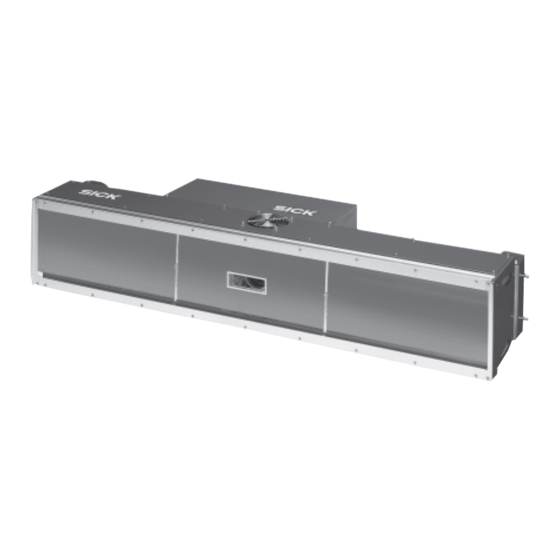
SD memory card for parameter cloning Fixing for bracket (2 x) 180° bracket Lens protection tube Fig. 3-2: View of the ICD890 camera and the ICI890 Illumination © SICK AG · Division Auto Ident · Germany · All rights reserved 8011325/0000/2006-10-24... -
Page 25: Included In Delivery
German and/or English issues explicitly ordered upon purchase Tab. 3-1: Included in the delivery of the ICR890 High-end CCD Camera System An overview of system components, in stock installation accessories, incremental encoders, cables and plug connections is available in Chapter 10.4 Ordering information,... -
Page 26: Contents Of The Cd-Rom
“SOPAS-ET Engineering Tool“: Configuration software for Windows PCs with integrated online help system (HTML files) • ICR890 Operating Instructions: PDF version in German and English as well as further publications for MSC800, VMS4xx/5xx • “Acrobat Reader“: Freely available PC software for reading PDF files... -
Page 27: Installation Requirements
Stable installation frames with sufficient load capacity and measurements suited to the ICR890 System (see Chapter 9.5 System dimensional drawing ICR890, page 108) • Four 180° brackets for the ICR890 System and the deflection mirror (included in delivery) • Shock absorbent and vibration free attachment Note An installation frame made of 80 mm (3.15 in) item aluminium profiles can be used for... -
Page 28: Electrical Installation Requirements
– Two 1 GBit Ethernet “IntelPro/1000 network card“ interface cards with 8254x (x = 0, 1, 2, 4, 5, 6, 7) chip set – GigE vision standard licence for real time image data transfer © SICK AG · Division Auto Ident · Germany · All rights reserved 8011325/0000/2006-10-24... -
Page 29: Product Features And Functions (Overview)
• Configuration mode • Reading operation Reading operation modi • Start/Stop operation • Object tracking (max. 10 objects per second, minimum gap 50 mm (1.97 in)) 8011325/0000/2006-10-24 © SICK AG · Division Auto Ident · Germany · All rights reserved... - Page 30 AUX data interface: RS 232, RS 422/485 serial, Ethernet or CAN (permanent transfer rate, data format and protocol) • CAN interface for integration into SICK CAN-SENSOR Network with the MSC800 or into a CAN Open Network • Ethernet interface (10/100 MBps), TCP/IP and FTP •...
-
Page 31: Method Of Operation
Chapter 3 ICR890 Method of operation This ICR890 System is an intelligent sensor system for automatic and non-contact detection and decoding of 1-D/2-D codes. In principle, the codes can be detected on any side of moving objects in a conveyor system. -
Page 32: Reading Configuration
(dynamic scanning frequency in lpi) can be configured: , ICR890, P , register tab I ROJECT ARAMETER EADING CONFIGURATION MAGE CAPTURING PROPERTIES © SICK AG · Division Auto Ident · Germany · All rights reserved 8011325/0000/2006-10-24... -
Page 33: Object Trigger Control
3.4.2 Object trigger control In order to initiate a reading process, the ICR890 System requires an appropriate signal (trigger). The start signal is emitted via an external reading pulse sensor (photoelectric reflex switch) as standard. As soon as an object has passed the reading pulse sensor, an “internal reading gate“... - Page 34 The illumination mode and the timeout for the ICI890 Illumination can be configured using the SOPAS-ET Configuration Software: , ICR890, P , register tab ROJECT ARAMETER EADING CONFIGURATION ONTROL LLUMINATION MODE © SICK AG · Division Auto Ident · Germany · All rights reserved 8011325/0000/2006-10-24...
-
Page 35: Position
ICR890 3.4.5 Position To ensure correct functioning of the ICR890 System, the position and angle of the camera and the deflection mirror have to be adjusted to the conveyor level. Fig. 3-9: Position of the ICR890 System and the tilt angle... -
Page 36: Image Requirement
ROJECT ARAMETER MAGE CQUISITION EQUEST Decoding The recorded image is analyzed by the ICR890 System. This identifies regions of interest in which codes are suspected. blue rectangle green rectangle green line Fig. 3-11: Image analysis (blue rectangle: Regions of interest; green rectangle: Successful decoding;... -
Page 37: Code Configuration
(the rear edge of the object has left the end of the reading area) or during the reading pulse if certain parameterizable conditions have been fulfilled. 8011325/0000/2006-10-24 © SICK AG · Division Auto Ident · Germany · All rights reserved... - Page 38 Tracking operation During the reading process, a maximum of 10 objects can be simultaneously situated, one behind the other, in the tracking operation, i. e. the ICR890 System must be able to unambiguously assign the read codes to the objects (Fig.
-
Page 39: Output Format
Network Although all important interfaces for displaying the reading results are available at the ICR890 System, the system is operated via the MSC800 Controller as standard. The MSC800 assumes system coordination for multi-side readings. The ICR890 System and the MSC800 can be networked via the CAN bus. -
Page 40: Digital Outputs
The digital inputs can be configured using the SOPAS-ET Configuration Software: , ICR890, P , register tabs S 1 and S ROJECT ARAMETER IGITAL NPUTS ENSOR ENSOR © SICK AG · Division Auto Ident · Germany · All rights reserved 8011325/0000/2006-10-24... -
Page 41: Indicators And Control Elements
The configured parameter values are saved as a parameter set in the internal EEPROM of the ICR890 System and on the SD memory card of the ICD890 Camera (cloning). If the camera needs replacing, the memory card allows convenient and rapid transfer of the parameter set to a new device (also see Chapter 7.3 Replacing a system or a component,... -
Page 42: Leds Of The Icd890 Camera
• DATA yellow Flashes during reading operation if data is being transferred between the ICR890 System and the main data interface at the host Tab. 3-5: LED indications © SICK AG · Division Auto Ident · Germany · All rights reserved... -
Page 43: Impacts On The Reading Quality
19.1 kHz. CCD line Conveyor speed (m/s) lpi = line per inch Fig. 3-16: Line resolution in the direction of transport (standard device, 8,192 pixels CCD sensor) 8011325/0000/2006-10-24 © SICK AG · Division Auto Ident · Germany · All rights reserved... - Page 44 Product description Chapter 3 Operating Instructions ICR890 High-end CCD Camera System Notes: © SICK AG · Division Auto Ident · Germany · All rights reserved 8011325/0000/2006-10-24...
-
Page 45: Installation
Installation preparations 4.2.1 Layout the components which are to be installed The following components of the ICR890 System have to be placed ready for installation: • Deflection mirror with protective film • ICI890 Illumination with protective caps •... -
Page 46: Selecting The Installation Location
(position of the components, distances, angles, etc.) are contained in a dimensional sheet and have to be adhered to when installing components. Abb. 4-1: Example of a project-specific dimensional sheet for installation © SICK AG · Division Auto Ident · Germany · All rights reserved 8011325/0000/2006-10-24... -
Page 47: Arrangement At The Conveyor System
The arrangement of the components above the conveyor system depends on the project- specific requirements and the number of systems. Abb. 4-3: Arrangement above the conveyor system for single-side reading from above 8011325/0000/2006-10-24 © SICK AG · Division Auto Ident · Germany · All rights reserved... -
Page 48: Chapter 4 Installation
90° 90° 90° 90° Arrangement for reading Arrangement for side reading from above/below (side view) (top view) Abb. 4-5: Arrangement at the conveyor system © SICK AG · Division Auto Ident · Germany · All rights reserved 8011325/0000/2006-10-24... -
Page 49: Installing And Adjusting The Device
After loosening the clamping screws, the angle of the brackets can be adjusted from 0° to 180° as required. To achieve this, the clamping screws can be screwed into the various threaded holes. 8011325/0000/2006-10-24 © SICK AG · Division Auto Ident · Germany · All rights reserved... -
Page 50: Installing The Deflection Mirror
4. Use four fastening screws to attach the illumination to the 180° brackets. 5. Remove the protective cap from the illumination and ensure that the sealing ring on the illumination is positioned correctly. © SICK AG · Division Auto Ident · Germany · All rights reserved 8011325/0000/2006-10-24... -
Page 51: Installing External Components
49). The photoelectric reflex switch has to be aligned as vertically as possible in the direction of transport. Install the photoelectric reflex switch onto the conveyor system. 8011325/0000/2006-10-24 © SICK AG · Division Auto Ident · Germany · All rights reserved... -
Page 52: Installing The Incremental Encoder
Chapter 7.2.3 Cleaning the deflection mirror, page 91). This prevents dirt from entering into the illumination housing. Carry out environmentally friendly disposal after decommissioning according to Chapter 7.4 Disposal, page © SICK AG · Division Auto Ident · Germany · All rights reserved 8011325/0000/2006-10-24... -
Page 53: Electrical Installation
54). Once electrical installation has been completed, the system is started up, adjusted and configured (see Chapter 6.1 Overview of the startup procedure, page 79). 8011325/0000/2006-10-24 © SICK AG · Division Auto Ident · Germany · All rights reserved... -
Page 54: Electrical Installation Preparation
ICR890 High-end CCD Camera System Electrical installation preparation The ICR890 System can be used for single-side reading with or without the MSC800 or for multi-side reading with the MSC800. These three possibilities of use are described in the following chapters, each one by means of a block diagram and a table of connections. -
Page 55: Tab. 5-1: Icr890 System (Stand-Alone Device) Without Msc800: Overview Of The Icd890 Camera Connections Which Have To Be Established
(3 m (9.84 ft)) no. 6029630 (5 m (16.4 ft)) Tab. 5-1: ICR890 System (stand-alone device) without MSC800: Overview of the ICD890 Camera connections which have to be established 8011325/0000/2006-10-24 © SICK AG · Division Auto Ident · Germany · All rights reserved... -
Page 56: Electrical Installation Of The Icr890 System With Msc800 (Single-Side Reading)
6029776 (10 m (32.8 ft)) Tab. 5-2: ICR890 System (stand-alone device) with MSC800: Overview of the ICD890 Camera connections which have to be established © SICK AG · Division Auto Ident · Germany · All rights reserved... -
Page 57: Tab. 5-3: Icr890 System (Stand-Alone Device) With Msc800: Overview Of The Msc800 Connections Which Have To Be Established
Cable provided by the USB or client ETHERNET Tab. 5-3: ICR890 System (stand-alone device) with MSC800: Overview of the MSC800 connections which have to be established Note Please refer to the MSC800 Operating Instructions (no. 8011540) for connection to the MSC800. -
Page 58: Electrical Installation Of The Icr890 System With Msc800 (Multi-Side Reading)
6029776 (10 m (32.8 ft)) Tab. 5-4: ICR890 System with MSC800 (multi-side reading): Overview of the ICD890 Camera connections which have to be established © SICK AG · Division Auto Ident · Germany · All rights reserved... -
Page 59: Tab. 5-5: Icr890 System With Msc800 (Multi-Side Reading): Overview Of The Msc800 Connections Which Have To Be Established
Cable provided by the USB or client ETHERNET Tab. 5-5: ICR890 System with MSC800 (multi-side reading): Overview of the MSC800 connections which have to be established Note Please refer to the MSC800 Operating Instructions (no. 8011540) for connection to the MSC800. -
Page 60: Electrical Connections And Cables
– RJ-45 connections: Grey, fixed to the device via a strap (cannot be lost) – Power supply: black RF interference in case of use in residential areas. ICR890 High-end CCD Camera System is exclusively intended for use in an industrial environment. 5.3.1... -
Page 61: Electrical Connections Of The Ici890 Illumination
8, plug Control data interface ICD890 Camera Harting 8, plug Power supply input 24 V DC HanQ8 Tab. 5-8: ICI890 Illumination: Function of the electrical connections 8011325/0000/2006-10-24 © SICK AG · Division Auto Ident · Germany · All rights reserved... -
Page 62: Electrical Connections Of The Msc800 (Overview)
12, terminals Input/Output CAN-SENSOR network 1 POWER Block 8, terminals Power supply input 24 V DC Tab. 5-9: MSC800-0000 logic controller: Function of the electrical connections (overview) © SICK AG · Division Auto Ident · Germany · All rights reserved 8011325/0000/2006-10-24... -
Page 63: Assembled Cables (Overview)
See Chapter 5.5.3 Wire colours assignment of assembled cables with open end, page 75 for the wire colour assignment of cables with open cable end. 8011325/0000/2006-10-24 © SICK AG · Division Auto Ident · Germany · All rights reserved... -
Page 64: Performing Electrical Installation
Power supply of the ICR890 System Power supply requirements A supply voltage of 24 V DC ± 10 % is required for the operation of the ICR890 System (functional extra-low voltage according to standard IEC 364-4-41 (VDE 0100 (Part 410)). -
Page 65: Data Interfaces Host/Aux
Both the HOST data interface (main data interface) as well as the AUX data interface (auxiliary data interface) of the ICR890 System can be operated as RS 232 version or as RS 422/485 version or be rerouted to the Ethernet interface. -
Page 66: Data Interface Can 1-In/Out
5.4.4 Data interface CAN 1-IN/OUT General conditions of the CAN interface The SICK-specific CAN-SENSOR network is based on the CAN bus, which is structured in line topology. Tab. 5-12 shows the maximum permissible CAN bus length, depending on the selected data transfer rate. -
Page 67: Tab. 5-14: Can Bus: Required Wire Cross Section, Depending On The Data Cable Length
The signals for the reading pulse and increment are transmitted to the ICR890 System via the CAN bus. Direct connection to the ICR890 System is, thus, not required. The HOST and AUX data interfaces as well as the signals of both switching outputs (for single-side reading) are accessible via the CAN bus at the MSC800. -
Page 68: Wiring The Ethernet Interface Host Ethernet
Connect the ICD890 Camera to the Ethernet network using the standardized data cable (patch ) no. 6029630. cable Chapter 6.3.2, page 81 for required settings at the PC and the ICR890 System. © SICK AG · Division Auto Ident · Germany · All rights reserved 8011325/0000/2006-10-24... -
Page 69: Wiring The Ethernet Interfaces Gbit 1 And Gbit 2
2. Connect the incremental encoder to switching input IN 2, as shown in Fig. 5-8. 3. For power supply via the ICD890 Camera, additionally establish connections between SGND and GND in the connector of the connection cable. 8011325/0000/2006-10-24 © SICK AG · Division Auto Ident · Germany · All rights reserved... -
Page 70: Wiring The Switching Outputs Result 1 And Result 2 (Out Connection)
Fig. 5-9. Note In the "Device Ready" function, the output supplies a static pulse if the ICR890 System is in reading operation. Recommendation Wire the outputs with a load resistance to test the switching functions using a high- resistance digital voltmeter. -
Page 71: Pin Assignments And Conductor Colouring Assignment
Supply voltage 24 V CAN_GND Ground CAN_H CAN bus (IN/OUT) CAN_L CAN bus (IN/OUT) Tab. 5-18: ICD890 Camera: Pin assignment of the 5-pole M12 sockets “CAN 1-OUT“/“CAN 2-OUT“ 8011325/0000/2006-10-24 © SICK AG · Division Auto Ident · Germany · All rights reserved... -
Page 72: Tab. 5-19: Icd890 Camera: Pin Assignment Of The 5-Pole M12 Plugs
RD–/RxD (RS 485/RS 232) Receiver–/Receiver TD+ (RS 485) Transmitter+ TD–/TxD (RS 485/RS 232) Transmitter–/Transmitter Ground Shield Shielding Tab. 5-22: ICD890 Camera: Pin assignment of the 8-pole M12 plug “HOST“ © SICK AG · Division Auto Ident · Germany · All rights reserved 8011325/0000/2006-10-24... -
Page 73: Tab. 5-23: Icd890 Camera: Pin Assignment Of The 4-Pole M12 Plug "Out
“HOST ETHERNET“ connection (Ethernet 10/100 MBps) Signal Function Transmitter+ Receiver+ TD– Transmitter– RD– Receiver– Tab. 5-26: ICD890 Camera: Pin assignment of the 4-pole M12 socket “HOST ETHERNET“ 8011325/0000/2006-10-24 © SICK AG · Division Auto Ident · Germany · All rights reserved... -
Page 74: Tab. 5-27: Icd890 Camera: Pin Assignment Of The 8-Pole Harting Hanq8 Plug
+24 V DC (ICI890_2) Power supply OUT GND (ICI890_2) Ground Protective ground Tab. 5-28: ICD890 Camera: Pin assignment of the 8-pole Harting HanQ8 socket “POWER OUT“ © SICK AG · Division Auto Ident · Germany · All rights reserved 8011325/0000/2006-10-24... -
Page 75: Ici890 Illumination Connections
RD–/RxD (RS 485/RS 232) yellow TD+ (RS 485) grey TD–/TxD (RS 485/RS 232) pink blue Shield Tab. 5-31: Wire colours assignment: Cable no. 6028420 (HOST/AUX), standard 8011325/0000/2006-10-24 © SICK AG · Division Auto Ident · Germany · All rights reserved... -
Page 76: Tab. 5-32: Wire Colours Assignment: Cables No. 6021166/No. 6021175
Signal Wire colour Result 1+ brown Result 1– white Result 2– blue Result 2+ black Tab. 5-34: Wire colours assignment: Cable no. 6027559 (OUT), standard © SICK AG · Division Auto Ident · Germany · All rights reserved 8011325/0000/2006-10-24... -
Page 77: Tab. 5-35: Wire Colours Assignment: Cable No. 2039398 (Icd890 Camera Power Supply), Standard
+24 V DC (ICI890_2) Wire 5: black GND (ICI890_2) Wire 6: black green-yellow Tab. 5-36: Wire colours assignment: Cable no. 2032926 (ICD890 Camera power supply), PVC-free 8011325/0000/2006-10-24 © SICK AG · Division Auto Ident · Germany · All rights reserved... - Page 78 Electrical installation Chapter 5 Operating Instructions ICR890 High-end CCD Camera System Notes: © SICK AG · Division Auto Ident · Germany · All rights reserved 8011325/0000/2006-10-24...
-
Page 79: Operation
• Start up the ICR890 System with the factory default settings. • Connect the PC with the SOPAS-ET Configuration Software to the ICR890 System or the MSC800. • In order to optimize the functionality of the system, adjust, if necessary, the ICR890 System and optimize the configuration of the system or the MSC800. -
Page 80: Default Setting For The Sopas-Et Configuration Software
Tab. 6-1: Default setting for the SOPAS-ET Configuration Software (excerpt) First startup The ICR890 System is optimized to the reading conditions on site via the SOPAS-ET Configuration Software. Starting point for this is the factory default setting which can be adjusted to optimize the system. -
Page 81: Overview Of The Configuration Procedure
Connect the PC via the cable no. 6028420 to the AUX connection or the ICR890 System HOST. Tab. 6-2: Connection between the PC with the SOPAS-ET Configuration Software and the ICR890 System/MSC800 8011325/0000/2006-10-24 © SICK AG · Division Auto Ident · Germany · All rights reserved... - Page 82 OMMUNICATION 2. Click on the A button. 3. Enter the IP address of the ICR890 System and confirm it via OK in the dialog window. The dialog window closes. A new entry appears in the IP A list. DDRESS CONFIGURATION 4.
-
Page 83: Configuring The Icr890 System/Msc800
Bitmap scaling/JPEG Quality Activate Diagnosis Output Output limited by code position Tab. 6-3: ICR890 System (stand-alone device) with MSC800: Overview of parameters which have to be set 8011325/0000/2006-10-24 © SICK AG · Division Auto Ident · Germany · All rights reserved... - Page 84 Control Duration Digital Inputs Sensor 1/2 Control Inverted Debouncing Tab. 6-3: ICR890 System (stand-alone device) with MSC800: Overview of parameters which have to be set (cont.) © SICK AG · Division Auto Ident · Germany · All rights reserved 8011325/0000/2006-10-24...
-
Page 85: Tab. 6-4: Icr890 System (Stand-Alone Device) With Msc800: Overview Of Parameters Which Have To Be Set
Duration Digital Inputs Sensor 1/2 Control Inverted Debouncing Realtime clock Tab. 6-4: ICR890 System (stand-alone device) with MSC800: Overview of parameters which have to be set 8011325/0000/2006-10-24 © SICK AG · Division Auto Ident · Germany · All rights reserved... -
Page 86: Tab. 6-5: Icr890 System (Stand-Alone Device) Without Msc800: Overview Of Parameters Which Have To Be Set
Stopbits Databits/Parity Hardware Protocol Blockcheck Serial Serial Auxilliary Interface Mode Tab. 6-5: ICR890 System (stand-alone device) without MSC800: Overview of parameters which have to be set © SICK AG · Division Auto Ident · Germany · All rights reserved 8011325/0000/2006-10-24... -
Page 87: Load Changed Parameter Sets Into The Device
Sensor 1/2 Control Inverted Debouncing Tab. 6-5: ICR890 System (stand-alone device) without MSC800: Overview of parameters which have to be set (cont.) 6.3.4 Load changed parameter sets into the device Changed parameter values are immediately transferred to the ICR890 System depending on the option (“Download Immediately“). -
Page 88: Changing The Device Password For The User Level "Authorized Client
A message confirms successful device password changes. Default setting The values of the default setting are permanently saved in the ICR890 System (ROM) and in the database of the SOPAS-ET Configuration Software in the device-specific jar file (see Fig. 6-1, page 80). -
Page 89: Maintenance
Cleaning the ICR890 System Recommendation In order to make use of the full optical reading capacity of the ICR890 System, the front window should be checked regularly (e. g. weekly) for soiling. This is especially recommended when operating the device in harsh conditions (dust, abrasion, humidity, finger prints, etc.). -
Page 90: Cleaning The Housing
Note Electrostatic charges cause dust particles to stick to the front window. This effect can be combated by using anti-static SICK synthetic cleaner (no. 5600006) in combination with a SICK lens cloth (no. 4003353). Use a clean, soft brush to free the front window from dust. -
Page 91: Cleaning The Deflection Mirror
2. Use a paper towel (recommended: “Kleenex“) to wipe the affected area. Only apply slight pressure to the mirror. Do not scour. 3. Allow the mirror to dry. Do not wipe the mirror dry! 8011325/0000/2006-10-24 © SICK AG · Division Auto Ident · Germany · All rights reserved... -
Page 92: Cleaning Further Optical Effective Surfaces
: clean here Trigger stop (optional) Trigger start Abb. 7-3: Cleaning of the external optical sensors (reading pulse generator, detector for object distance) © SICK AG · Division Auto Ident · Germany · All rights reserved 8011325/0000/2006-10-24... -
Page 93: Replacing A System Or A Component
Incorrect or damaged system components have to be removed and replaced with either new or repaired components. Repairs to the ICR890 System should only be carried out by qualified and authorized SICK AG service staff. Risk of injuries due to falling components! The combined weight of the ICD890 Camera and the ICI890 Illumination is approx. -
Page 94: Replacing The Deflection Mirror
2. Reconnect all external cables to the camera. 3. Switch on the power supply to the ICR890 System. The ICR890 System starts up and loads the parameter set from the memory card into its permanent parameter memory (EEPROM) after initialisation. -
Page 95: Disposal
Inoperable or irreparable devices must be removed and disposed of in an environmentally friendly manner in accordance with valid country-specific waste disposal guidelines. At present SICK AG will not accept the return of any devices which can no longer be operated or repaired. - Page 96 Maintenance Chapter 7 Operating Instructions ICR890 High-end CCD Camera System Notes: © SICK AG · Division Auto Ident · Germany · All rights reserved 8011325/0000/2006-10-24...
-
Page 97: Troubleshooting
Troubleshooting Operating Instructions Chapter 8 ICR890 Troubleshooting This chapter describes how errors at the ICR890 High-end CCD Camera System can be recognised and eliminated. Overview of errors and malfunctions which could occur 8.1.1 Installation error • The ICR890 System has been unsuitably aligned to objects with 1-D/2-D codes (e.g. -
Page 98: Detailed Malfunction Analysis
The LEDs can display possible malfunctions or errors. Please refer to the system information for further details. 8.2.2 System information The ICR890 System displays errors in various ways. The error output is hierarchised and always allows a detailed analysis: • Communication errors can occur while transmitting telegrams to the ICR890 System. -
Page 99: Tab. 8-1: Request "Query Warnings
00A4h 0255h 0005h 00A4h 0256h 0006h 0256h 0000h 4C0ACC0Ch 00A4h 0255h 0005h 00A4h 0256h 0006h 0256h 0000h 4C0ACC0Bh 00A4h 0255h 0005h 00A4h 0256h 0006h 0256h 0000h 4C0ACC0Ch 00A4h 0255h 0005h 00A4h 0256h 0006h 0256h 0000h 8011325/0000/2006-10-24 © SICK AG · Division Auto Ident · Germany · All rights reserved... -
Page 100: Tab. 8-3: Request "Query Errors
0000h 0000h 0000h 0000h 0000h 0000h 0000h 0000h 00000000h 0000h 0000h 0000h 0000h 0000h 0000h 0000h 0000h 00000000h 0000h 0000h 0000h 0000h 0000h 0000h 0000h 0000h 00000000h 0000h 0000h 0000h 0000h 0000h 0000h 0000h 0000h © SICK AG · Division Auto Ident · Germany · All rights reserved 8011325/0000/2006-10-24... -
Page 101: St Error Status In The Reading Result Of A 1-D Code (Bar Code)
Chapter 8 ICR890 ST error status in the reading result of a 1-D code (bar code) With the respective configuration, the ICR890 System transfers the ST error status to the output string of the HOST data interface. Value Meaning Possible cause Remedy Error-free reading “Good Read“... -
Page 102: Sick Support
However, the camera or the illumination can be rapidly replaced by the user. See Chapter 7.3 Replacing a system or a component, page Please contact our local SICK office or subsidary if an error occurs which cannot be eliminated: •... -
Page 103: Technical Data
“GBit Ethernet“ data interface 2 x, 10 MBps to 1 GBps, real-time image output, FTP and Gig-E Vision standard, Half/Full duplex Tab. 9-1: Technical specifications for the ICR890 Camera 8011325/0000/2006-10-24 © SICK AG · Division Auto Ident · Germany · All rights reserved... - Page 104 1) Camera and illumination can be replaced independently of each other. 2) In preparation 3) Including decoder Tab. 9-1: Technical specifications for the ICR890 Camera (contd.) © SICK AG · Division Auto Ident · Germany · All rights reserved 8011325/0000/2006-10-24...
-
Page 105: Data Sheet For Ici890 Illumination
0 to +40 °C (+32 to +104 °F)/–20 to +70 °C (–4 to +158 °F) Ambient operating temperature/Storage temperature Max. rel. humidity 95 %, no condensation Colour SICK Blue (RAL 5012) Tab. 9-3: Technical specifications for deflection mirror 8011325/0000/2006-10-24 © SICK AG · Division Auto Ident · Germany · All rights reserved... -
Page 106: Specification Diagram
1,800 70.9 2,000 78.8 2,200 86.7 2,400 94.6 2,600 102.4 2,800 110.3 Reading distance (mm) 3,000 118.2 Abb. 9-1: Reading areas of the ICR890 System (standard) © SICK AG · Division Auto Ident · Germany · All rights reserved 8011325/0000/2006-10-24... -
Page 107: Max. Resolution Across The Direction Of Transport
Max. resolution in the direction of transport CCD line Conveyor speed (m/s) lpi = line per inch Abb. 9-3: Line resolution in the direction of transport (standard device, 8,192 pixels CCD sensor) 8011325/0000/2006-10-24 © SICK AG · Division Auto Ident · Germany · All rights reserved... -
Page 108: System Dimensional Drawing Icr890
System dimensional drawing ICR890 inch 0.35 1.58 1.97 13.7 1,190 46.9 1,224 48.2 1,400 55.2 3,000 118.2 All dimensions in mm Abb. 9-4: Dimensions of the ICR890 System © SICK AG · Division Auto Ident · Germany · All rights reserved 8011325/0000/2006-10-24... - Page 109 39.4 1,400 55.2 2,100 82.7 3,000 118.2 All dimensions in mm Abb. 9-5: Total dimensions of the ICR890 System and the free space required for connecting 8011325/0000/2006-10-24 © SICK AG · Division Auto Ident · Germany · All rights reserved...
-
Page 110: Deflection Mirror Dimensional Drawing
ICR890 High-end CCD Camera System Deflection mirror dimensional drawing inch 0.16 0.75 69.8 101.6 1125.6 44.3 All dimensions in mm Abb. 9-6: Dimensions of the deflection mirror © SICK AG · Division Auto Ident · Germany · All rights reserved 8011325/0000/2006-10-24... -
Page 111: Appendix
Parameter values altered via commands are at first only active in the current parameter set in the working memory (RAM) of the ICR890 System. To save in the permanent memory, the altered parameter set must be copied into the EEPROM using a special command, this ensures that the alterations are not lost when the power supply is switched off. -
Page 112: Calculating Code Length Of A Bar Code
2) Apart from a few exceptions, every printed character represents an ASCII character which has to be decoded. Extended for code 39. The number of characters in the ICR890 System data string may be greater than the number of characters in the print image for code 93, code 128 and EAN 128, since they are made up of several character sets. -
Page 113: Ordering Information
Tab. 10-2: Ordering information: ICR890 High-end CCD Camera System Note For an exact type designation of the ICR890 System, see the type plate on the device. 8011325/0000/2006-10-24 © SICK AG · Division Auto Ident · Germany · All rights reserved... -
Page 114: Accessories: Controller And Object Distance Detector
MLG Modular Light Grid On request VMS410/VMS510 Volume Measurement System On request VMS410/VMS510 Volume Measurement System Tab. 10-3: In stock accessories: Controller and object distance detector © SICK AG · Division Auto Ident · Germany · All rights reserved 8011325/0000/2006-10-24... -
Page 115: Accessories: Cables And Connectors
HanQ8 socket and open end (wire end ferrules), IP 65, PVC-free (32.8 ft) supply (open end) (11 AWG) Tab. 10-4: In stock accessories: Cables and connectors 8011325/0000/2006-10-24 © SICK AG · Division Auto Ident · Germany · All rights reserved... -
Page 116: Accessories: Incremental Encoder
10 to 30 V DC, operating temperature 0 to +60 °C (+32 to +140 °F). With fixing bracket and fixing material, 10 m (32.8 ft) connection cable with 5-pole M12 socket and open end. For operation with the ICR890 System and an MLG Light Grid. -
Page 117: Supplementary Documentation
3) see 1) and 2) 4) “Bar Code Scanners Manuals & Software“ on CD-ROM (no. 2029112), enclosed with CLV490 Tab. 10-7: Supplementary documentation for the ICR890 System 8011325/0000/2006-10-24 © SICK AG · Division Auto Ident · Germany · All rights reserved... -
Page 118: Glossary
Aperture angle α Aperture within the boundaries of which the ICR890 System is able to analyze codes (through the lenses). A V-shaped area appears radially in front of the reading window, across the direction of transport (reading from above), in which the codes to be read must be positioned. - Page 119 ICR890 Capture area Zone which the ICR890 System sets up around a moving code using the increment manager and the code position comparison. Allows, among other functions, the separation of codes with identical content, where the code type is the same.
- Page 120 Distance of the lens focal point in front of the reading window. The distance determines the DOF (depth of field) via the ICR890 System lenses, in which the code can be analyzed. The depth of field depends on the resolution.
- Page 121 Host/CAN or Ethernet interface in case of a no read. Consists of the reading data with/without defined error string or is completely eliminated. In its default setting, the ICR890 System generates the reading data as no read format with the "NOREAD" error string. Object distance Gauge for focusing the camera.
- Page 122 In the case of permanent storage, the parameter set is also transferred to the EEPROM of the ICR890 System and saved as a current data set after switching off. The default setting is deposited in a Read Only Memory (ROM) irrespective of this.
- Page 123 (data output) in the direction of transport of the MSC800 at the end of the reading area. Networking the ICR890 System to the MCS800 is carried out via the CAN interface. The ICR890 System manages recorded objects by means of an internal object tracking list.
-
Page 124: Ec Declaration Of Conformity
The complete EC Declaration of Conformity can be requested from SICK AG. Abb. 10-1: EC Declaration of Conformity for the ICD890 Camera (page 1, scaled down version) © SICK AG · Division Auto Ident · Germany · All rights reserved 8011325/0000/2006-10-24... - Page 125 Appendix Operating Instructions Chapter 10 ICR890 Abb. 10-2: EC Declaration of Conformity for the ICI890 Illumination (page 1, scaled down version) 8011325/0000/2006-10-24 © SICK AG · Division Auto Ident · Germany · All rights reserved...
- Page 126 Appendix Chapter 10 Operating Instructions ICR890 High-end CCD Camera System Notes: © SICK AG · Division Auto Ident · Germany · All rights reserved 8011325/0000/2006-10-24...
-
Page 127: Code Samples (Decodeable)
(19.7 mil) (19.7 mil) (11.8 mil) Abb. 10-3: Code samples of 1-D codes of various module widths (print ratio 2:1) and 2-D code of various cell sizes 8011325/0000/2006-10-24 © SICK AG · Division Auto Ident · Germany · All rights reserved... - Page 128 Phone +81 (0)3 3358 1341 E-Mail support@sick.jp Nederlands Phone +31 (0)30 229 25 44 E-Mail info@sick.nl Norge More representatives and agencies Phone +47 67 81 50 00 in all major industrial nations at E-Mail austefjord@sick.no www.sick.com SICK AG | Waldkirch | Germany | www.sick.com...
Need help?
Do you have a question about the ICR890 and is the answer not in the manual?
Questions and answers