Sign In
Upload
Manuals
Brands
Sick Manuals
Measuring Instruments
FLOWSIC100 Flare
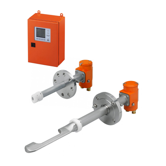
Sick FLOWSIC100 Flare Gas Flow Meter Manuals
Manuals and User Guides for Sick FLOWSIC100 Flare Gas Flow Meter. We have
4
Sick FLOWSIC100 Flare Gas Flow Meter manuals available for free PDF download: Operating Instructions Manual, Addendum To Operating Instructions
sick FLOWSIC100 Flare Operating Instructions Manual (266 pages)
for flare gas and steam flow measurements
Brand:
sick
| Category:
Measuring Instruments
| Size: 18 MB
Table of Contents
Table of Contents
4
1 Important Information
9
About this Document
10
Main Hazards
11
Hazards Due to Hot, Cold (Cryogenic) or Aggressive Gases, or High Pressure
11
Hazards with Electrical Equipment
11
Hazards Due to Explosive or Combustible Gases
11
Hazards Due to Electrostatic Discharges
12
Intended Use
13
Purpose of the Device
13
Correct Use
13
Restrictions of Use
17
Responsibility of User
19
General Information
19
Safety Information and Protective Measures
20
Transport Safety Device for Retractable Sender/Receiver Units
21
2 Product Description
23
System Basic Information
24
Functional Principle
24
System Configuration
26
Communication between Sender/Receiver Units and Control Unit
28
System Overview
29
System Components
31
FLSE100 Sender/Receiver Unit
31
Mounting Accessories
54
Nozzle Installation Tool
58
MCUP Control Unit
59
Connection Cables and Cable Glands
66
Meter Body Option (Spoolpiece)
68
Computations
69
Calculation and Calibration of Volume Flow
69
Mass Flow and Molecular Weight Determination
70
Necessity for Using External Pressure and Temperature Transmitters
70
Response Time
71
Check Cycle
72
Zero Point Control
72
Span Test
73
Analog Output of Check Cycle
73
3 Assembly and Installation
75
Project Planning
76
Determining the Measuring and Installation Location
77
Further Notes for Project Planning
80
Notes for Installation of Sender/Receiver Units in 1-Path, 2-Paths or 3X1 Path
81
Configuration
81
Preparation Work
82
General Notes
82
Special Notes for Handling the Meter Body Option
83
Assembly
84
Fitting the Nozzles on the Pipeline (Measuring Systems Without Meter Body)
86
Installing the Meter Body (Option) in the Pipeline
99
Installing the MCUP Control Unit
100
Installing the MCUP with Option "Set Fixing Plate for 2-Inch Post
104
Installing the Sun Roof MCUP (Option)
105
Sun Roof MCUP for Wall Mounting
105
Sun Roof MCUP Mounting on 2-Inch Post
108
General Notes for Installation of Sender/Receiver Units
111
Installing Non-Retractable Sender/Receiver Units
112
Installing Retractable Sender/Receiver Units
112
Installing the Sun Roof for the Sender/Receiver Units
115
Installing the Sun Roof for the Sender/Receiver Units
116
Dimensional Drawings
117
Electrical Installation
119
General Information, Prerequisites
119
Cable Requirements
119
Requirements for Installation in the Ex Zone
122
Connection of Sender/Receiver Units
127
MCUP Connections
129
Cabling
136
Fitting and Connecting the Interface and I/O Module Options
142
Connection of External Pressure and Temperature Transmitters
149
Connection of Relay Contacts
149
4 Start-Up and Parameter Settings
151
Basics
152
General Information
152
Installing the Operating and Parameter Program SOPAS ET
153
Connecting to the Device
155
Information on Using the Program
161
Standard Start-Up
164
Entering Application-Specific Parameters in the Sender/Receiver Units
165
Entering Application Specific Parameters for Single-Path Configuration
167
In the MCUP
167
Configuration of Application-Specific Parameters for 10" Pipelines and 2-Path
168
Configurations
168
Determining the Check Cycle
172
Setting the Analog Outputs Parameters
173
Setting Parameters for the Pulse Output
175
Setting the Analog Inputs Parameters
176
Defining the Limit Value
179
Logbook Function
180
Data Backup
180
Starting Normal Measuring Operation
184
Advanced Start-Up
186
Entering Customer Data
186
Entering Counter Function Parameters
187
Data Archives
187
Entering Process Parameters
193
Setting Interface Module Parameters
194
Setting Modbus and HART® Bus Module Parameters
196
Application-Specific Flow Calibration
197
Operating/Setting Parameters Via the Optional LC-Display
198
General Information on Use
198
Menu Structure
199
Parameter Setting
200
Using SOPAS ET to Modify Display Settings
201
5 Maintenance
203
General
205
Recognizing Malfunctions
205
Maintaining the Sender/Receiver Units
206
Removing Sender/Receiver Units
206
Cleaning the Sender/Receiver Unit
207
Maintaining the MCUP for Use Zone 2
208
6 Specifications
209
Technical Data
210
Dimensions and Part Numbers
213
FLOWSIC100 EX-S Sender/Receiver Units
213
FLOWSIC100 EX/EX-RE Sender/Receiver Units
219
FLOWSIC100 EX-PR Sender/Receiver Units
222
Sender/Receiver Units - Parts List
225
Connection Cables
228
Junction Box for Ex Zone 2 (for ATEX Versions Only)
230
Nozzles
231
Additional Accessories for Retractable Sender/Receiver Units
233
MCUP Control Unit
233
Options for MCUP Control Unit
238
Inputs/Outputs
238
Interface Module
238
Interface Modules for MCUP 19" Version
238
Password
238
Sealing Installation Instruction
239
SICK Commissioning Check List
241
Connection Diagrams for MCUP Ex Zone 1 - Configuration Examples with Optional
250
Modules
250
Wiring Diagrams for USA and Canada
253
Flse100-Exs/Flse100-Expr
253
Flse100-Ex/Flse100-Exre
259
Connection of External Pressure and Temperature Transmitters
264
Advertisement
Sick FLOWSIC100 Flare Operating Instructions Manual (184 pages)
Gas Flow Rate Measuring Device
Brand:
Sick
| Category:
Measuring Instruments
| Size: 6 MB
Table of Contents
Table of Contents
3
1 Important Information
7
Intended Use
8
Responsibility of User
8
General Information
8
Safety Information and Protective Measures
9
General Information
9
Hazard through Electrical Equipment
9
Hazard through Hot, Corrosive And/Or Pressurized Gases
9
Hazards through Ultrasonic Signals
9
Behavior During a Purge/Cool Air Failure
10
Detecting Malfunctions
10
Preventing Damage
10
2 Product Description
11
System Features and Areas of Application
12
System Overview and Functional Principle
13
System Overview
13
Communication between Sender/Receiver Units and Control Unit
14
Functional Principle
15
System Components
17
FLSE100 Sender/Receiver Unit
17
Standard Sender/Receiver Units
22
Sender/Receiver Units with Internal Cooling
25
Purged Sender/Receiver Units
27
Flange with Tube
28
Weatherproof Cover
29
MCU Control Unit
29
Connection Cable
39
Purge Air Unit Option
40
Cooling Air Control Option for Device Types M-AC and H-AC
41
Optional Sets for Emergency Air Supply for Device Types with Purge and Cooling
41
Air Operation
41
Emergency Air Supply for Device Types M-AC and H-AC
42
Emergency Air Supply for Device Types PM, PH and PH-S
43
Measuring Tube Option
43
Computations
44
Calculating and Calibrating the Volume Flow
44
Temperature Calibration
45
Damping Time
46
Check Cycle
47
Zero Point Control
47
Span Test
48
Check Cycle Output on the Analog Output
48
3 Assembly and Installation
49
Project Planning
50
Determining the Measurement and Installation Location
51
Further Planning Information
54
Selecting the Flanges with Tube
57
Assembly
60
Installing the Flanges with Tube
60
Duct/Pipe Diameter > 0.5 M
60
Duct/Tube Diameter < 0.5 M
63
Installing the Control Unit
66
Installing the Junction Box
67
Installing the Sender/Receiver Units
67
Installation of the Weatherproof Cover for the Sender/Receiver Units
68
Installing the Purge Air Unit Option (Device Type PM, PH, PH-S)
69
Installing the Emergency Air Supply Option for Device Types PM, PH and PH-S
70
Installing the Weatherproof Cover for the Purge Air Unit Option
72
Installting the Impact Protector / Dust Protector Options
73
Impact Protection for FLSE100-H, HAC, PH and PHS
73
Dust Protector for FLSE100-PR
75
Installing the Structure-Borne Noise Damping Set Option K100/K75
75
Installation
78
General Instructions, Prerequisites
78
Installing the Purge/Cooling Air Supply
78
Control Unit MCU-P with Integrated Cooling Air Supply
79
And H-AC)
79
Separate Cooling Air Supply in Connection Box (Device Type M-AC and H-AC)
79
Purge Air Unit (Device Type PM, PH, PH-S)
80
Installing the Purge Air and Cooling Air Reducer Option
81
Installing the Cooling Air Control Option for Device Types M-AC and H-AC
82
Installing Optional Sets for Emergency Air Supply for Devices with Purge/Cooling
87
Air Operation
87
Emergency Air Supply for Device Types M-AC and H-AC
87
Emergency Air Supply for Device Types PM, PH and PHS
93
Installing the Sender/Receiver Unit
95
Connecting the Control Unit MCU
97
Connecting the Control Unit in a 19" Housing
98
Terminating the Sender/Receiver Units When Operating the FLOWSIC100 with
106
2-Path Measuring" Configuration
106
Checking the Sender/Receiver Unit(S) - MCU Connection
106
Bus Addressing
107
Hardware Addressing
107
Installing and Connecting the Interface and I/O Module Options
107
4 Start-Up and Parameter Settings
113
Basics
114
General Information
114
Installing SOPAS ET
114
Connecting the Device
116
Changing the Language
116
Connecting to the Device Via the "Device Family" Mode
117
Search Settings)
117
Connecting to the Device with Advanced Mode
119
Information on Using SOPAS ET
122
Standard Start-Up Procedure
126
Setting "Maintenance" Mode
127
Setting the System Data Parameters on the FLOWSIC100 Sensor
127
Setting the Check Cycle Parameters
130
Configuring the Analog Output
131
Configuring the Analog Inputs
133
Setting the Damping Time
134
Data Backup
134
Starting Normal Measuring Operation
138
Signal Waveform
138
Advanced Start-Up
144
Changing the Application Setting
144
Configuring Optional Analog Modules
145
Configuring the Optional Interface Module
146
Configuring the Ethernet Module
147
Changing the Field Bus Address for the Profibus Module
149
Configuring the Temperature Curve for the Cooling Air Control Option for Device
150
Types M-AC and H-AC
150
Calibrating Flow Rate and Temperature Measurement
151
Operating / Configuring with the LC-Display Option
152
General Information on Use
152
Menu Structure
153
Configuring
154
Changing the Application Setting
154
Changing the Display Settings with SOPAS ET
155
5 Maintenance
157
General Information
158
Maintaining the Sender/Receiver Units
159
Removing the Sender/Receiver Units
159
Cleaning the Sender/Receiver Unit
160
Maintaining the Cooling Air Supply of the Internally Cooled Types M-AC and H-AC
161
Inspection
161
Control Unit with Integrated Cooling Air Supply
162
Maintaining the External Purge Air Unit Option
163
Inspection
163
Replacing the Filter Element
164
6 Specification
165
Technical Data
166
Standard Components
168
Dimensions, Part no
169
Sender/Receiver Units
169
Flange with Tube
174
MCU Control Unit
176
Cooling Air Supply in Connection Box for FLOWSIC100 M-AC and H-AC
179
Junction Box for Connection Cable
180
Miscellaneous
182
Control Unit, MCU 19
183
Consumable Parts for 2-Years Operation
183
Control Unit MCU with Integrated Purge Air Supply
183
Optional External Purge Air Unit
183
SICK FLOWSIC100 Flare Addendum To Operating Instructions (88 pages)
Brand:
SICK
| Category:
Measuring Instruments
| Size: 8 MB
Table of Contents
Table of Contents
3
1 About this Document
7
Function of this Document
8
Scope of Application
8
Target Groups
8
Data Integrity
8
Further Information
8
2 For Your Safety
9
Basic Safety Information
10
Intended Use
10
Main Hazards
11
Hazards Due to Hot, Cold (Cryogenic) or Aggressive Gases, or High Pressure
11
Hazard through Electrical Equipment
11
Hazards through Explosive or Ignitable Gases
11
Hazards through Electrostatic Discharges
12
Retraction Mechanism of the Sender/Receiver Units
12
Operation in Potentially Explosive Atmospheres
13
Specific Conditions
14
Specific Conditions Relating to All FLSE Models
14
Specific Conditions Relating to the FLSE100-XT with Intrinsically Safe
14
Transducers
14
Use of FLSE100-XT, Depending on the Temperature Code and Process
14
Temperature
15
Permissible Gas Temperature, Depending on the Temperature Code of the Sender
15
Receiver Units
15
Warning Information on Device
16
Requirements on the Personnel's Qualification
16
Restrictions on Use
17
3 Product Description
19
Product Identification
20
Sender/Receiver Units
22
Material for Parts with Process Gas Contact
25
Spool Piece Option
26
Transport and Storage
26
Transport Protection
26
Special Notes for Handling the Spool Piece Option
27
4 Installation
29
Safety Information
30
Scope of Delivery
30
Fitting the Spool Piece (Option)
31
Installation Sequence
32
Geometry Calculator
32
Installation Accessories
33
Nozzles, Blind Flanges and Seals
34
Ball Valve
35
Nozzle Installation Tool
36
Fitting the Nozzles on the Pipeline (Measuring System Without Spool Piece)
37
General Preparation Work
37
Determine the Nozzle Position for Cross-Duct Versions
38
Determining the Nozzle Position for the Probe Version
41
Welding the Nozzle on
42
Drilling Holes into the Pipeline if Plant Is in Operation (Hot Tap)
46
Fitting the Sender/Receiver Units
47
Calculating the Wetted Part Length Wl and Geometric Installation Parameters
48
Calculating the Wetted Part Length for Cross-Duct Versions
51
Calculating the Wetted Part Length for the Probe Version
52
Tightening the Self-Cutting Ring
54
Installing Sender/Receiver Units
56
Leak Tightness Check
58
Pulling the Sender/Receiver Units Back
58
Fitting the Venting Valve
60
Fitting the Weatherproof Cover for the Sender/Receiver Units
61
Overview
61
Fitting the Weatherproof Cover
62
5 Electrical Installation
65
General Instructions, Prerequisites
66
Cable Specifications
66
Cable Glands
66
Requirements for Installation in the Ex Zone
67
Connection Overview
69
Connection Diagrams
70
6 Commissioning
71
General Information
72
Commissioning Procedure
72
7 Technical Data
73
FLSE100-XT Sender/Receiver Units
74
F1F-S
74
F1F-M
75
F1F-H
75
F1F-P
76
Application Limits
77
Derating of Pressure Resistance
79
Dimension Drawings
80
8 Spare Parts
81
Recommended Spare Parts for FLSE100-XT Sender/Receiver Units
82
9 Accessories (Optional)
83
Accessories for FLSE100-XT Sender/Receiver Units
84
Advertisement
SICK FLOWSIC100 Flare Addendum To Operating Instructions (42 pages)
Brand:
SICK
| Category:
Measuring Instruments
| Size: 1 MB
Table of Contents
Table of Contents
3
Important Information
5
About this Document
6
For Your Safety
6
Modbus RS485 and Modbus TCP
7
General Information
8
Installing and Connecting the Interface Module in the MCU
9
Putting the Modbus Module into Operation
11
Modbus RS485
11
Modbus TCP
12
Installing the Configuration Program
12
Integrating the Modbus Module in the Network
13
Configuring the Modbus TCP Module
17
Configuring the MCU for the Modbus TCP Module
20
Checking the Communication
21
Profibus Dp
23
General Information
24
Hardware
24
Connection and Termination
25
PROFIBUS Wiring - hat Rail Module
25
PROFIBUS Wiring - Plug-In Module
26
GSD File
27
Ethernet Triplex
29
General Information
30
Configuration
30
Technical Data
30
Ethernet Service
31
Installing and Connecting the Ethernet Service Module in the MCU
32
Putting the Ethernet Service Module into Operation
33
Installing the Configuration Program
33
Integrating the Ethernet Service Module in the Network
34
Configuring the Ethernet Service Module
38
Checking the Communication
40
Advertisement
Related Products
SICK FLOWSIC100 Flare-XT
SICK FLOWSIC100-XT-P
SICK FLOWSIC100-XT-S
SICK FLOWSIC100-XT-R
SICK FLOWSIC100-XT-M
SICK FLOWSIC100-XT-H
SICK FLOWSIC600
SICK FLOWSIC60
SICK FLOWSIC550
SICK FLOWSIC30
Sick Categories
Accessories
Security Sensors
Measuring Instruments
Scanner
Barcode Reader
More Sick Manuals
Login
Sign In
OR
Sign in with Facebook
Sign in with Google
Upload manual
Upload from disk
Upload from URL