Sign In
Upload
Manuals
Brands
SICK Manuals
Accessories
DT1000
User Manuals: SICK DT1000 Range Distance Sensor
Manuals and User Guides for SICK DT1000 Range Distance Sensor. We have
5
SICK DT1000 Range Distance Sensor manuals available for free PDF download: Operating Instructions Manual
SICK DT1000 Operating Instructions Manual (124 pages)
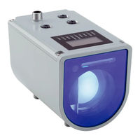
Distance sensor
Brand:
SICK
| Category:
Measuring Instruments
| Size: 4 MB
Table of Contents
Table of Contents
3
1 About this Document
8
Information on the Operating Instructions
8
Explanation of Symbols
8
Further Information
9
2 Safety Information
10
Intended Use
10
Improper Use
10
Limitation of Liability
10
Modifications and Conversions
11
Requirements for Skilled Persons and Operating Personnel
11
Operational Safety and Particular Hazards
11
Laser Radiation
12
Hot Surface
13
Warning Signs on the Device
13
UL Conformity
13
3 Product Description
15
Scope of Delivery
15
Product Characteristics
15
Design
16
Product ID
16
Switching Functions
17
Measured Value Technology
18
Interfaces
19
Signal Inputs/Outputs
19
SSI (Synchronous Serial Interface)
20
RS-422 Interface
21
PROFINET IO Interface
28
Ethernet Interface
37
Display and Operating Elements
37
4 Transport and Storage
39
Transport
39
Unpacking
39
Transport Inspection
39
Storage
39
5 Mounting
41
Mounting Procedure
41
Mounting Instructions
41
Select and Mount the Reflector (DL1000 Only)
43
Mounting/Disassembling Additional Filter (DT1000 Only)
44
Placement of Multiple Distance Sensors
45
Mounting the Alignment Bracket and Distance Sensor
47
Aligning Distance Sensor
48
6 Electrical Installation
51
Safety
51
Wiring Instructions
51
Digital Outputs
52
Analog Output
53
Connecting the Device Electrically
54
Pin Assignment
54
7 Operation
56
Operating Concept
56
Main Display Level
56
Menu Groups
57
Menu Items
57
Parameter Input
57
Selection Lists
58
Standard Buttons
58
Measured Value Displays
59
Distance Display
59
Signal Level Display
59
Temperature Display
59
Operating Time Display
60
Speed Display
60
Overview of Parameters
60
Measuring Behavior
60
IO Interfaces
61
Device Information
62
Parameterization Via SOPAS ET
62
8 Reference
64
Measurement Menu Group: Basic Settings
64
Measuring Mode
64
Defining the Measurement Cycle Time
65
Defining the Distance Offset
65
Defining the Measuring Direction
66
Configuring the Rain and Snow Filter
66
Activating/Deactivating the Fog Filter
67
Measurement Menu Group: Expert Settings
67
Configuring the Distance Averaging Filter
67
Activating/Deactivating the Kalman Filter
68
Configuring the Speed Filter
68
Defining the Echo Selection
69
Configuring the Distance Range
69
Configuring Signal Level Range Limits
70
Configuring Delay Time for "No Echo
70
Defining Substitute Values for "No Echo
71
Configuring User-Defined Substitute Values
71
Behaviour on Error
72
Interface Menu Group
72
Defining the Switching Point for Distance Value (Distance to Object)
72
Defining the Switching Hysteresis for the Distance Value
73
Defining the Switching Point Active State for the Distance Value
73
Defining the Switching Window for the Distance Value
74
Defining the Switching Window Hysteresis for the Distance Value
74
Defining the Switching Window Active Status for the Distance Value
75
Defining the Switching Point for the Object Speed Value
75
Defining the Switching Point Hysteresis for the Object Speed Value
75
Defining the Monitoring Direction for the Object Speed Value
76
Defining the Switching Point Active State for the Object Speed Value
76
Assigning a Switching Event to the Service Functions
77
Defining the Active State for Service Functions
78
Configuring the QA Analog Output
78
Configuring the Switching Input
78
Defining the Active State for Digital Input
79
Device Menu Group
79
Switching the Laser on and off
79
Configuring the Heater
80
Defining the Language
80
Defining Units of Measure
81
Adjusting the Display Contrast
81
Adjusting the Display Brightness
81
Defining the Display Orientation
81
Communication Menu Group
82
Configuring the Serial Interface
82
Defining the RS-422 Data Transmission Rate
82
Defining the RS-422 Data Format
83
Setting the Continuous RS-422 Output
83
Defining the RS-422 Output Cycle Time
84
Defining the RS-422 Data Protocol
84
Defining the Distance Value Resolution for the RS-422 Data Transfer
85
Defining the Speed Value Resolution for the RS-422 Data Transfer
85
Defining SSI Coding
85
Defining the Distance Value Resolution for the SSI Data Transfer
86
Displaying the PROFINET Station Name
86
Displaying the PROFINET IP Address
87
Displaying the PROFINET Subnet Mask
87
Displaying the PROFINET Gateway Address
87
Displaying the PROFINET MAC Address
87
Activating Ethernet DHCP
88
Defining Ethernet IP Addressing Mode
88
Entering an Ethernet IP Address
88
Entering an Ethernet Subnet Mask
89
Entering an Ethernet Gateway Address
89
Displaying an Ethernet MAC Address
89
Activating Ethernet DHCP
89
Info Menu Group
90
Retrieving Firmware Information
90
Retrieving Hardware Information
90
Retrieving the Counter Readings of Switching Events
90
Deleting the Counter Readings of Switching Events
90
Menu Tree Overview
91
Main Menu
91
Measurement Menu Group: Basic Settings
91
Measurement Menu Group: Expert Settings
92
IO Interface Menu Group: Digital Input In1
93
IO Interface Menu Group: Digital Output Q1
94
IO Interface Menu Group: Digital Output Q2
95
IO Interface Menu Group: Analog Output QA
96
Device Menu Group
96
Communication Menu Group
97
Info Menu Group
98
9 Maintenance
99
Cleaning
99
Maintenance Plan
99
10 Troubleshooting
100
Information for the Service Case
102
Returns
102
Repairs
102
Disposal
102
11 Technical Data
104
Performance
104
Measuring Range Diagrams
106
Repeatability Diagrams
108
Measurement Accuracy Diagrams
114
Interfaces
115
Mechanics/Electronics
116
Ambient Data
116
Classifications
117
Dimensional Drawings
118
12 Accessories
121
13 Appendix
122
EU Declaration of Conformity / Certificates
122
Licenses
122
Cybersecurity
122
Advertisement
SICK DT1000 Operating Instructions Manual (122 pages)
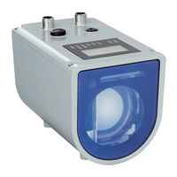
Distance Sensor
Brand:
SICK
| Category:
Accessories
| Size: 4 MB
Table of Contents
Table of Contents
3
About this Document
8
Information on the Operating Instructions
8
Explanation of Symbols
8
Further Information
9
Safety Information
10
Intended Use
10
Improper Use
10
Limitation of Liability
10
Modifications and Conversions
11
Requirements for Skilled Persons and Operating Personnel
11
Operational Safety and Particular Hazards
11
Laser Radiation
12
Hot Surface
13
Warning Signs on the Device
13
Product Description
14
Scope of Delivery
14
Product Characteristics
14
Design
15
Product ID
15
Switching Functions
16
Measured Value Technology
17
Interfaces
18
Signal Inputs/Outputs
18
SSI (Synchronous Serial Interface)
19
RS-422 Interface
20
PROFIBUS DP Interface
26
Ethernet Interface
36
Display and Operating Elements
36
Transport and Storage
38
Transport
38
Unpacking
38
Transport Inspection
38
Storage
38
Mounting
40
Mounting Procedure
40
Mounting Instructions
40
Select and Mount the Reflector (DL1000 Only)
42
Mounting/Disassembling Additional Filter (DT1000 Only)
43
Placement of Multiple Distance Sensors
44
Mounting the Alignment Bracket and Distance Sensor
46
Aligning Distance Sensor
47
Electrical Installation
50
Safety
50
Wiring Instructions
50
Digital Outputs
51
Analog Output
52
Connecting the Device Electrically
53
Pin Assignment
53
Operation
55
Operating Concept
55
Main Display Level
55
Menu Groups
56
Menu Items
56
Parameter Input
56
Selection Lists
57
Standard Buttons
57
Measured Value Displays
58
Distance Display
58
Signal Level Display
58
Temperature Display
58
Operating Time Display
59
Speed Display
59
Overview of Parameters
59
Measuring Behavior
59
IO Interfaces
60
Device Information
61
Parameterization Via SOPAS ET
61
Reference
63
Measurement Menu Group: Basic Settings
63
Measuring Mode
63
Defining the Measurement Cycle Time
64
Defining the Distance Offset
64
Defining the Measuring Direction
65
Configuring the Rain and Snow Filter
65
Activating/Deactivating the Fog Filter
66
Measurement Menu Group: Expert Settings
66
Configuring the Distance Averaging Filter
66
Activating/Deactivating the Kalman Filter
67
Configuring the Speed Filter
67
Defining the Echo Selection
68
Configuring the Distance Range
68
Configuring Signal Level Range Limits
69
Configuring Delay Time for "No Echo
69
Defining Substitute Values for "No Echo
70
Configuring User-Defined Substitute Values
70
Behaviour on Error
71
Interface Menu Group
71
Defining the Switching Point for Distance Value (Distance to Object)
71
Defining the Switching Hysteresis for the Distance Value
72
Defining the Switching Point Active State for the Distance Value
72
Defining the Switching Window for the Distance Value
73
Defining the Switching Window Hysteresis for the Distance Value
73
Defining the Switching Window Active Status for the Distance Value
74
Defining the Switching Point for the Object Speed Value
74
Defining the Switching Point Hysteresis for the Object Speed Value
74
Defining the Monitoring Direction for the Object Speed Value
75
Defining the Switching Point Active State for the Object Speed Value
75
Assigning a Switching Event to the Service Functions
76
Defining the Active State for Service Functions
77
Configuring the QA Analog Output
77
Configuring the Switching Input
78
Defining the Active State for Digital Input
78
Device Menu Group
79
Switching the Laser on and off
79
Configuring the Heater
79
Defining the Language
79
Defining Units of Measure
80
Adjusting the Display Contrast
80
Adjusting the Display Brightness
80
Defining the Display Orientation
80
Communication Menu Group
81
Configuring the Serial Interface
81
Defining the RS-422 Data Transmission Rate
81
Defining the RS-422 Data Format
82
Setting the Continuous RS-422 Output
82
Defining the RS-422 Output Cycle Time
83
Defining the RS-422 Data Protocol
84
Defining the Distance Value Resolution for the RS-422 Data Transfer
84
Defining the Speed Value Resolution for the RS-422 Data Transfer
84
Defining SSI Coding
85
Defining the Distance Value Resolution for the SSI Data Transfer
85
Entering a PROFIBUS Address
86
Defining the IP Addressing Mode
86
Entering an IP Address
86
Entering a Subnet Mask
87
Entering a Gateway Address
87
Displaying a MAC Address
87
Activating DHCP and Displaying Information
87
Info Menu Group
88
Retrieving Firmware Information
88
Retrieving Hardware Information
88
Retrieving the Counter Readings of Switching Events
88
Deleting the Counter Readings of Switching Events
89
Menu Tree Overview
89
Main Menu
89
Measurement Menu Group: Basic Settings
90
Measurement Menu Group: Expert Settings
91
IO Interface Menu Group: Digital Input In1
92
IO Interface Menu Group: Digital Output Q1
93
IO Interface Menu Group: Digital Output Q2
94
IO Interface Menu Group: Analog Output QA
95
Device Menu Group
95
Communication Menu Group
96
Info Menu Group
97
Maintenance
98
Cleaning
98
Maintenance Plan
98
Troubleshooting
99
Information for the Service Case
101
Returns
101
Repairs
101
Disposal
101
Technical Data
103
Performance
103
Measuring Range Diagrams
105
Repeatability Diagrams
107
Measurement Accuracy Diagrams
112
Interfaces
113
Mechanics/Electronics
114
Ambient Data
114
Classifications
115
Dimensional Drawings
116
SICK DT1000 Operating Instructions Manual (110 pages)
Distance sensor
Brand:
SICK
| Category:
Accessories
| Size: 3 MB
Table of Contents
Table of Contents
3
1 About this Document
8
Information on the Operating Instructions
8
Explanation of Symbols
8
2 Safety Information
9
Intended Use
9
Improper Use
9
Limitation of Liability
9
Modifications and Conversions
10
Requirements for Skilled Persons and Operating Personnel
10
Operational Safety and Particular Hazards
11
Laser Radiation
11
Hot Surface
12
Warning Signs on the Device
12
UL Conformity
12
3 Product Description
14
Scope of Delivery
14
Product Characteristics
14
Design
15
Product ID
15
Switching Functions
16
Measured Value Technology
17
Interfaces
18
Signal Inputs/Outputs
18
SSI (Synchronous Serial Interface)
19
RS-422 Interface
20
Ethernet Interface
26
Display and Operating Elements
27
4 Transport and Storage
29
Transport
29
Unpacking
29
Transport Inspection
29
Storage
29
5 Mounting
31
Mounting Procedure
31
Mounting Instructions
31
Select and Mount the Reflector (DL1000 Only)
33
Mounting/Disassembling Additional Filter
34
Placement of Multiple Distance Sensors
36
Mounting the Alignment Bracket and Distance Sensor
37
Aligning Distance Sensor
39
6 Electrical Installation
42
Safety
42
Wiring Notes
42
Digital Outputs
43
Analog Output
44
Connecting the Device Electrically
45
Pin Assignment
45
7 Operation
47
Operating Concept
47
Main Display Level
47
Menu Groups
48
Menu Items
48
Parameter Input
48
Selection Lists
49
Standard Buttons
49
Measured Value Displays
50
Distance Display
50
Signal Level Display
50
Temperature Display
50
Operating Time Display
51
Speed Display
51
Overview of Parameters
51
Measuring Behavior
51
IO Interfaces
52
Device Information
52
8 Reference
53
Measurement Menu Group: Basic Settings
53
Measuring Mode
53
Defining the Measurement Cycle Time
54
Defining the Distance Offset
54
Defining the Measuring Direction
55
Configuring the Rain and Snow Filter
55
Activating/Deactivating the Fog Filter
56
Measurement Menu Group: Expert Settings
56
Configuring the Distance Averaging Filter
56
Activating/Deactivating the Kalman Filter
57
Configuring the Speed Filter
57
Defining the Echo Selection
58
Configuring the Distance Range
58
Configuring Signal Level Range Limits
59
Configuring Delay Time for "No Echo
59
Defining Substitute Values for "No Echo
60
Configuring User-Defined Substitute Values
60
Behaviour on Error
61
Interface Menu Group
61
Defining the Switching Point for Distance Value (Distance to Object)
61
Defining the Switching Hysteresis for the Distance Value
62
Defining the Switching Point Active State for the Distance Value
62
Defining the Switching Window for the Distance Value
63
Defining the Switching Window Hysteresis for the Distance Value
63
Defining the Switching Window Active Status for the Distance Value
64
Defining the Switching Point for the Object Speed Value
64
Defining the Switching Point Hysteresis for the Object Speed Value
64
Defining the Monitoring Direction for the Object Speed Value
65
Defining the Switching Point Active State for the Object Speed Value
65
Assigning a Switching Event to the Service Functions
66
Defining the Active State for Service Functions
67
Configuring the QA Analog Output
67
Configuring the Switching Input
68
Defining the Active State for Digital Input
68
Device Menu Group
69
Switching the Laser on and off
69
Configuring the Heater
69
Defining the Language
69
Defining Units of Measure
70
Adjusting the Display Contrast
70
Adjusting the Display Brightness
70
Defining the Display Orientation
70
Communication Menu Group
71
Configuring the Serial Interface
71
Defining the RS-422 Data Transmission Rate
71
Defining the RS-422 Data Format
72
Setting the Continuous RS-422 Output
72
Defining the RS-422 Output Cycle Time
73
Defining the RS-422 Data Protocol
74
Defining the Distance Value Resolution for the RS-422 Data Transfer
74
Defining the Speed Value Resolution for the RS-422 Data Transfer
74
Defining SSI Coding
75
Defining the Distance Value Resolution for the SSI Data Transfer
75
Defining the IP Addressing Mode
76
Entering an IP Address
76
Entering a Subnet Mask
76
Entering a Gateway Address
77
Displaying a MAC Address
77
Activating DHCP and Displaying Information
77
Info Menu Group
77
Retrieving Firmware Information
77
Retrieving Hardware Information
78
Retrieving the Counter Readings of Switching Events
78
Deleting the Counter Readings of Switching Events
78
Menu Tree Overview
79
Main Menu
79
Measurement Menu Group: Basic Settings
79
Measurement Menu Group: Expert Settings
80
IO Interface Menu Group: Digital Input In1
81
IO Interface Menu Group: Digital Output Q1
82
IO Interface Menu Group: Digital Output Q2
83
IO Interface Menu Group: Analog Output QA
84
IO Interface Menu Group: Digital Output Q3
85
IO Interface Menu Group: Digital Output Q4
86
IO Interface Menu Group: Digital Input In2
87
Device Menu Group
88
Communication Menu Group
89
Info Menu Group
90
9 Maintenance
91
Cleaning
91
Maintenance Plan
91
10 Troubleshooting
92
Information for the Service Case
93
Returns
94
Repairs
94
Disposal
94
11 Technical Data
95
Performance
95
Measuring Range Diagrams
97
Repeatability Diagrams
99
Interfaces
103
Mechanics/Electronics
103
Ambient Data
104
Classifications
104
Dimensional Drawings
105
12 Accessories
108
13 Appendix
109
Advertisement
SICK DT1000 Operating Instructions Manual (100 pages)
Distance sensor
Brand:
SICK
| Category:
Accessories
| Size: 5 MB
Table of Contents
Table of Contents
3
1 About this Document
7
Information on the Operating Instructions
7
Explanation of Symbols
7
Scope of Delivery
7
Customer Service
8
2 Safety Information
9
Intended Use
9
Incorrect Use
9
Limitation of Liability
9
Modifications and Conversions
9
Requirements for Skilled Persons and Operating Personnel
9
Operational Safety and Particular Hazards
10
Laser Radiation
10
Hot Surface
11
Warning Signs on the Device
11
UL Conformity
11
Environmental Protection
12
3 Product Description
13
Product Characteristics
13
Design
14
Product ID
14
Switching Functions
15
Interfaces
16
Signal Inputs/Outputs
16
SSI (Synchronous Serial Interface)
16
RS-422 Interface
18
4 Transport and Storage
24
Transport
24
Unpacking
24
Transport Inspection
24
Storage
24
5 Mounting
26
Mounting Procedure
26
Mounting Instructions
26
Select and Mount the Reflector (DL1000 Only)
28
Placement of Multiple Distance Sensors
29
Mounting the Alignment Bracket and Distance Sensor
30
Aligning Distance Sensor
32
6 Electrical Installation
34
Safety
34
Wiring Notes
34
Technical Data for Electrical Installation
34
Digital Outputs
35
Analog Output
36
Connecting the Device Electrically
37
Pin Assignment
38
7 Operation
39
Operating Concept
39
Main Display Level
39
Menu Groups
39
Menu Items
40
Parameter Input
40
Selection Lists
41
Standard Buttons
41
Measured Value Displays
42
Distance Display
42
Signal Level Display
42
Temperature Display
42
Operating Time Display
43
Speed Display
43
Overview of Parameters
43
Measuring Behavior
43
IO Interfaces
43
Device Information
44
8 Reference
45
Measurement Menu Group: Defaults
45
Measuring Mode
45
Defining the Measurement Cycle Time
46
Defining the Distance Offset
46
Defining the Measuring Direction
47
Configuring the Rain and Snow Filter
47
Activating/Deactivating the Fog Filter
48
Measurement Menu Group: Advanced Settings
48
Configuring the Distance Averaging Filter
48
Activating/Deactivating the Kalman Filter
49
Configuring the Speed Filter
49
Defining the Echo Selection
49
Configuring the Distance Range
50
Configuring the Signal Level Range
50
Detecting Delay Time for "No Echo
51
Defining Substitute Values for "No Echo
52
Configuring User-Defined Substitute Values
52
Behaviour on Error
53
Interface Menu Group
53
Defining the Switching Point for Distance Value (Distance to Object)
53
Defining the Switching Hysteresis for the Distance Value
54
Defining the Switching Point Active Status for the Distance Value
54
Defining the Switching Window for the Distance Value
55
Defining the Switching Hysteresis for the Distance Value
55
Defining the Switching Window Active Status for the Distance Value
56
Defining the Switching Point for the Object Speed Value
56
Defining the Switching Point Hysteresis for the Object Speed Value
57
Defining the Monitoring Direction for the Object Speed Value
57
Defining the Switching Point Active Status for the Object Speed Value
58
Assigning a Switching Event to the Service Functions
58
Defining the Active Status for Service Functions
59
Configuring the QA Analog Output
60
Configuring the Switching Input
60
Defining the Active Status for Digital Input
61
Device Menu Group
61
Switching the Laser on and off
61
Configuring the Heater
61
Defining the Language
62
Defining Units of Measure
62
Adjusting the Display Contrast
62
Adjusting the Display Brightness
63
Defining the Display Orientation
63
Communication Menu Group
63
Configuring the Serial Interface
63
Defining the RS-422 Data Transmission Rate
64
Defining the RS-422 Data Format
64
Setting the Continuous RS-422 Output
65
Defining the RS-422 Output Cycle Time
66
Defining the RS-422 Data Protocol
66
Defining the Distance Value Resolution for the RS-422 Data Transfer
67
Defining the Speed Value Resolution for the RS-422 Data Transfer
67
Defining SSI Coding
67
Defining the Distance Value Resolution for the SSI Data Transfer
68
Defining the IP Addressing Mode
68
Entering an IP Address
69
Entering a Subnet Mask
69
Entering a Gateway Address
69
Displaying a MAC Address
70
Activating DHCP and Displaying Information
70
Info Menu Group
70
Retrieving Firmware Information
70
Retrieving Hardware Information
70
Retrieving the Counter Readings of Switching Events
71
Deleting the Counter Readings of Switching Events
71
Menu Tree Overview
71
Main Menu
72
Measurement Menu Group: Defaults
72
Measurement Menu Group: Advanced Settings
73
IO Interface Menu Group: Digital Input In1
74
IO Interface Menu Group: Digital Output Q1
75
IO Interface Menu Group: Digital Output Q2
76
IO Interface Menu Group: Analog Output QA
77
IO Interface Menu Group: Digital Output Q3
78
IO Interface Menu Group: Digital Output Q4
79
IO Interface Menu Group: Digital Input In2
80
Device Menu Group
81
Communication Menu Group
82
Info Menu Group
83
9 Maintenance
84
Cleaning
84
10 Troubleshooting
85
Information for the Service Case
87
Returns
87
Repairs
87
Disposal
87
11 Technical Data
88
Performance
88
Interfaces
94
Mechanics/Electronics
95
Ambient Data
95
Classifications
95
Dimensional Drawings
96
EU Declaration of Conformity
98
12 Accessories
99
SICK DT1000 Operating Instructions Manual (142 pages)
Distance sensor
Brand:
SICK
| Category:
Accessories
| Size: 5 MB
Table of Contents
Table of Contents
3
1 About this Document
8
Information on the Operating Instructions
8
Explanation of Symbols
8
Further Information
9
2 Safety Information
10
Intended Use
10
Improper Use
10
Cybersecurity
10
Limitation of Liability
10
Modifications and Conversions
11
Requirements for Skilled Persons and Operating Personnel
11
Operational Safety and Particular Hazards
12
Warning Signs on the Device
13
UL Conformity
13
3 Product Description
14
Scope of Delivery
14
Product Characteristics
14
Design
15
Product ID
15
Switching Functions
16
Measured Value Technology
17
Interfaces
19
Signal Inputs/Outputs
19
SSI (Synchronous Serial Interface)
19
RS-422 Interface
20
Ethernet/Ip Interface
27
Ethernet Interface
46
Display and Operating Elements
47
4 Transport and Storage
49
Transport
49
Unpacking
49
Transport Inspection
49
Storage
49
5 Mounting
50
Mounting Procedure
50
Mounting Instructions
50
Select and Mount the Reflector (DL1000 Only)
52
Mounting/Disassembling Additional Filter (DT1000 Only)
53
Placement of Multiple Distance Sensors
54
Mounting the Alignment Bracket and Distance Sensor
56
SOPAS ET Configuration Software
71
8 Reference
74
Measurement Menu Group: Basic Settings
74
Measuring Mode
74
Defining the Measurement Cycle Time
75
Defining the Distance Offset
75
Defining the Measuring Direction
76
Configuring the Rain and Snow Filter
76
Activating/Deactivating the Fog Filter
77
Measurement Menu Group: Expert Settings
77
Configuring the Distance Averaging Filter
77
Activating/Deactivating the Kalman Filter
78
Configuring the Speed Filter
78
Defining the Echo Selection
79
Configuring the Distance Range
79
Configuring Signal Level Range Limits
80
Configuring Delay Time for "No Echo
80
Advertisement
Related Products
SICK DT35
SICK DT50-2 Pro
SICK DT80 IO-Link
SICK Dx35
SICK deTec7C4C-EV04530A10000
SICK deTec16C4C-EV09030A10000
SICK deTec30C4C-EV15030C10000
SICK deTec38C4C-EV19530B10000
SICK deTec39C4C-EV19530C10000
SICK deTec44C4C-SV03030C10000
SICK Categories
Accessories
Security Sensors
Measuring Instruments
Scanner
Barcode Reader
More SICK Manuals
Login
Sign In
OR
Sign in with Facebook
Sign in with Google
Upload manual
Upload from disk
Upload from URL