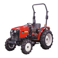
Sign In
Upload
Manuals
Brands
Shibaura Manuals
Lawn Mower
ST330
Shibaura ST330 Manuals
Manuals and User Guides for Shibaura ST330. We have
2
Shibaura ST330 manuals available for free PDF download: Workshop Manual, Specification Sheet
Shibaura ST330 Workshop Manual (251 pages)
Brand:
Shibaura
| Category:
Tractor
| Size: 16.21 MB
Table of Contents
Table of Contents
3
Index
3
Chapter 1 GENERAL
5
External Views
6
Specifications & Performance
7
Precautions before Servicing
9
Basic Understanding on Servicing
9
Metric Bolt Torque Specifications
10
Bolt Head Identification Mark
10
Sequence of Dismantling the Tractor
11
Flow Chart
11
Disassembly
12
Steering Wheel, Instrument Panel
12
Bonnet (Hood)
12
ENGINE and HST UNIT REMOVAL (9×3 and HST)
12
Air Cleaner Assembly
13
Radiator Assembly
13
Dash Board (Shrouding)
13
Throttle Cable
13
Fuel Tank
14
Side Step
14
Suction Pipe
14
Diverter Valve
15
Rubber and Drive Shaft
15
Power Steering Piping
15
Wiring
15
Hst Piping, Oil Cooler, Oil Filter with Base
16
Battery Base, Front Axle Support
16
Firewall
16
Power Steering Control Valve, Column
17
Engine
17
Clutch Housing (Hst Only)
17
Hst Unit
18
Hst Shift Link Assembly
18
Seat Track
19
Front Side Cover High-Pressure Inlet Tube
19
Rops/Rear Wheel
19
TRANSMISSION REMOVAL (9×3 and HST)
19
Fenders, Toolbox, Center Frame
20
Transmission Cover Plate
20
Case Cover Brake Rod
20
Suction Tube, Return Tube
21
MID Pto, Rear Pto and Range Gear Change Lever Assembly
21
Front Wheel Drive
21
Lift Cylinder Housing
22
Rear Axle Assembly
22
Installation and Trial Run
24
Tightening Torque for Piping
24
Front Axle Support Bolt
25
Hst Cruise Control Rod
25
Battery Cable
26
Steering Wheel Nut
26
Trial Running
26
Chapter 2 Engine
27
Engine Sectional View
29
Engine Specifications
30
Disassembly, Inspection and Reassembly
31
Disassembly and Inspection of Engine Main Parts
35
Inspection and Service
35
Rocker Arm Ass’y
35
Cylinder Head Ass’y
36
Valve Guide and Valve Stem
36
Valve Seat
37
Valve Spring
38
Cylinder Block
39
Distortion on Cylinder Block Top Surface (MM)
39
Clearance between Piston Pin Hole and Piston Pin (MM)
40
Piston
40
Piston and Piston Ring
40
Piston Skirt Bottom Longer Dia. (MM)
40
Clearance between Piston Ring Groove and Ring (MM)
41
Piston Pin
41
Piston Ring
41
Piston Ring End Gap (MM)
41
Axial Play of Connecting Rod and Crank Pin (MM)
42
Clearance between Bush and Piston Pin (MM)
42
Connecting Rod
42
Torsion and Parallelism of Connecting Rod (MM)
42
Connecting Rod Metal
43
Reassembly (Piston and Connecting Rod)
43
Center Bearing
44
Disassembly, Inspection and Reassembly of Bearing Holder
44
Rear Bearing Holder Thickness (MM)
44
Thrust Washer
44
Reassembly (Bearing Holder, Center Bearing, Thrust Washer)
45
Crankshaft Bearing (Bush)
46
Crankshaft Run-Out (MM)
47
Irregular Wear Limit of Crankshaft Journal and Pin (MM)
47
Cam Shaft Ass’y
48
Flywheel and Ring Gear
48
Timing Gear
48
Oil Flow
49
Oil Filter
50
Oil Pump
50
Removal from Engine
50
Thermostat
51
Water Pump Assembly and Thermostat
51
Radiator
52
Fuel Filter
53
Fuel Passage
53
Governor
53
Maximum Speed Set Bolt
53
Injection Pump
54
Nozzle and Holder
55
Specifications
55
Air Cleaner
56
Cautions before Assembly
57
Engine Reassembly
57
Measure the Endplay of Crankshaft
57
Flywheel
58
Oil Seal
58
Rear Plate
58
Rear Plate Tightening Torque
58
Suction Filter
59
Camshaft Ass’y
60
Front Plate
60
Oil Level Gauge
60
Oil Pan
60
Idle Gear
61
Timing Gear Case
61
Crankshaft Pulley
62
Injection Pump Assembly
62
Cap
63
Pushrod
63
Bypass Hose
64
Oil Pressure Switch
64
Valve Clearance Adjustment
64
Water Pump Ass’y
64
Alternator
65
Head Cover
65
Nozzle and Holder Ass’y
65
Return Pipe COMPL
65
Trouble Shooting
66
Engine Maintenance Standards Table
68
Tractor Main Body
74
Chapter 3 . Tractor Main Body
75
Front Axle
75
Sectional Views
75
Case Cover
76
Tie Rod Ass’y
76
Tire/Front Axle Support
76
Transmission Case
76
Arm
77
Differential Shaft (Left)
77
Transmission Case (Idler)
77
Wheel Shaft Case (Left)
77
Case Cover Ass’y
78
Drive Pinion
78
Final Pinion
78
Final Pinion (Left)
78
Casing
79
Final Gear and Final Pinion
79
Play of Spline in Rotating Direction (MM)
79
Clearance between Pinion Shaft and Differential Pinion (MM)
80
Differential Ass’y
80
Backlash of Bevel Gear (Differential)
81
Reassembly of Drive Pinion
81
Front Wheel
82
Steering Angle
82
Toe-In
82
Wheel Alignment
82
Clutch
83
Clutch Shaft
84
Disassembly, Inspection and Reassembly of Clutch
84
Release Bearing
84
Release Hub
84
Clutch Disk COMPL
85
Release Hub and Clutch Fork
85
Drive Shaft
86
Pedal Shaft
86
Adjustment of Clutch Pedal Play
87
Assembly to Main Body
87
Pressure Plate and Clutch Disk
87
Improper Disengagement of Clutch
88
Noise and Vibration of Clutch
88
Slippery Clutch
88
Troubleshooting
88
Counter Shaft
91
Shifter Fork
91
Shifter Rod
91
PTO Counter Shaft
92
Reverse Gear Shaft
92
Drive Shaft (4WD)
93
Retainer
93
Shifter Fork (4WD)
93
Backlash of Gear
94
Bearing
94
Clearance between Shifter Fork and Slide Gear (MM)
94
Shifter Fork and Slide Gear
94
Main Shifter Rod and Fork
95
Transmission 1 for HST
96
Name of Units
97
Drive Shaft (PTO)
100
Hst Unit
103
Motor Removal - Reference Figure 373Y
104
Shaft Removal
104
Charge Pump Removal
105
Port Block Removal Reference
105
Pump Shaft Removal
105
Swash Plate
106
Charge Pump Ass’y
107
Shoe Thickness
107
Port Block Assembly
108
Tightening Torque of Parts
108
Charge Pump Case Assembly
109
Cover Assembly
109
Trochoid Pump Assembly
109
Trunnion Cover Assembly
109
Cylinder Block Assembly
110
Motor Shaft Assembly
110
Pump Shaft Assembly
110
Pump Case and Motor Case Assemble
111
High Pressure Relief Valve Inspection
114
Inspection and Adjustment
114
Low-Pressure Relief Valve Inspection
115
Centering Spring and Rod Assembly
116
Link Adjustment
117
Neutral Position Adjustment
117
Brake Switch Relay (385230290)
118
Cruise Latch Relay (385230300)
118
Cruise Latch Switch
118
Shift Arm and Magnet
118
Cancels Hst Cruise Control
119
Diode
119
Hst Wirings
119
Electrical Magnet
120
ON Position (from SET Position)
120
Cruise Control Switch
121
HST Troubleshooting
124
HST Cruise Control System Troubleshooting
125
One Speed PTO Model
126
Two Speed PTO Model
127
Transmission 2 for 9×3 Model
128
Differential Fork
129
Differential Lock Pedal
129
Differential Shaft
129
Main Shaft
129
Differential Ass'y
130
Differential Support
130
PTO Shaft
132
Bracket
134
Transmission 2 for Hst Model
135
MID PTO Counter Shaft
138
MID PTO Gear Case
138
Shift Arm
138
Change Lever Linkage
148
Main Change Lever Ass’y
148
Clearance between Shift Arm and Bush
149
4WD Change Lever
150
Range Shift, Pto and 4Wd Change Lever
150
Real Axle and Brake
151
Brake Cover
152
Brake Ass’y
152
Disk (Lining)
152
Stator
152
Disk
153
Rear Axle Ass’y
154
Brake Adjustment
155
Rear Wheel
155
Adjustment of Tread
156
Front Wheel Settings
156
Rear Wheel Settings
156
Rear Wheel Tread Settings
156
Hand Brake
157
Trouble Shooting
160
External View
161
Steering and Linkage
161
Power Steering Control Valve
162
Power Steering Pump
164
Troubleshooting (Steering Control Unit)
165
Hydraulic System
166
Hydraulic Circuit
166
Cylinder Head
167
Lift Arm (Right)
167
Lift Arm (Left)
168
Hydraulic Arm Shaft
168
Piston and Cylinder
168
Top Link Bracket
169
Control Valve Assembly
171
Operation (Flow of Oil)
172
When Valve Is at "O" Position
172
When Valve Is at "S" Position
172
Relief Valve
173
Pressure Adjustment of Relief Valve
174
Neutral Position
176
Oil Flow - Neutral Position
176
Raising Position
177
Lowering Position
178
Bypass Spool
179
Control Valve Spool
180
Lowering Valve
180
Check Valve・Shut-Off Valve
180
Spool, Check Valve, Lowering Valve and Shut-Off Valve
181
Tightening Torque of each Parts
182
Adjustment of Sensitivity
182
Adjust the Lever Operating Force
183
Link System
184
Position Control
184
Increase of Compression Force from Top Link
185
Reduction of Compressive Force from Top Link
185
Setting of Resistance Sensitivity
185
Joint Use of Position Control and Draft Control
186
Adjustment of Link
187
Remote Control Valve
188
Single Acting Control Valve (with Detent Position)
188
Double Acting Control Valve
189
Single Acting or Double Acting Change over Control Valve
190
Spool
191
O-Ring and Wiper Ring
191
Electric Unit and Accessories
194
Component Location
197
Descriprion or Testing
198
Battery
198
Fusible Link
198
Key Switch
199
Safety Start Switches
199
Fuse Block
200
Relay for Safety Start
200
Diode for Brake Switch
202
Relay for Glow Lamp
203
Diode for Hst Circuit
203
Fuel Shutoff Solenoid
203
Fuel Level Sending Unit
205
Engine Glow Plugs
206
Diode for Alternator
207
Engine Coolant Temperature Sending Unit
207
Reference Value
207
Relay for Hst Brake Switch
208
Engine Oil Pressure Switch
209
Instrument Panel-Component Operation and Servicing
210
Headlight Switch
214
Headlight
215
Glow Lamp Timer
216
Electric Cruise Control Switch
217
Testing Cruise Control Rocker Switch
218
Cruise Control Magnet
219
Parking Brake Switch
220
Combination Switch
221
Brake Lamp Switch
222
Hst Cruise Latch Reley
225
Hazard Lamp Relay
225
Flasher and Hazard Relay
225
Horn
226
Trailer Socket
227
Fuse Block for Headlamp
227
Starting Motor
238
Maintenance
243
Pinion Dose Not Advance Even Though the Key Switch Is Turned on
243
Cultivating Implement Installing Device
247
Three-Point Link
247
Name of Major Parts of Three-Point Link
247
Standards for Three-Point Link
247
Pto
248
Service and Cautions for Handling of 3-Point Link
248
Maintenance Standard Table
249
Advertisement
Shibaura ST330 Specification Sheet (1 page)
Shibaura Tractor Specification Sheet
Brand:
Shibaura
| Category:
Lawn Mower
| Size: 2.18 MB
Advertisement
Related Products
Shibaura ST324
Shibaura ST321
Shibaura ST329
Shibaura ST318
Shibaura ST333
Shibaura ST440
Shibaura ST445
Shibaura SR525
Shibaura SX21
Shibaura SX24
Shibaura Categories
Lawn Mower
Controller
Tractor
Water Pump
Engine
More Shibaura Manuals
Login
Sign In
OR
Sign in with Facebook
Sign in with Google
Upload manual
Upload from disk
Upload from URL