Sign In
Upload
Manuals
Brands
Servomex Manuals
Measuring Instruments
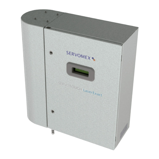
SERVOTOUGH LaserExact 2950
User Manuals: Servomex SERVOTOUGH LaserExact 2950 Gas
Manuals and User Guides for Servomex SERVOTOUGH LaserExact 2950 Gas. We have
1
Servomex SERVOTOUGH LaserExact 2950 Gas manual available for free PDF download: Operator's Manual
Servomex SERVOTOUGH LaserExact 2950 Operator's Manual (72 pages)
For Windows Software v. 6.1
Brand:
Servomex
| Category:
Measuring Instruments
| Size: 2 MB
Table of Contents
Table of Contents
3
1 Introduction
7
Safety Information
7
General
7
SERVOTOUGH Laserexact Monitor, Operator Manual 02950001A
7
Measuring Principle
8
Figure 1-1: Measuring Principle
9
Instrument Description
10
Software
11
Figure 1-2: Block Diagram of Instrument Electronics
11
Laser Classification
12
Product Data
13
SERVOTOUGH Laserexact
13
2 Preparations
14
Tools and Other Equipment
14
Flow Conditions
14
Cell Materials
14
Cables and Electrical Connections
14
Sticky Gases
15
3 Installation
16
Labelling
16
Installation and Adjustments
17
Figure 3-1: Servotough L
17
SERVOTOUGH Laserexact Installation
18
Purging of Laser Beam Alignment Chamber
20
Figure 3-2:Purge Connections
21
Laser Module Purge
21
Start-Up
22
Alignment of Laser Beam
22
Figure 3-3:Alignment Chamber Access Panel
24
Figure 3-4:Coupling Mirrors
24
Connecting Apc
25
Installing a Modem
25
4 The Service Program
26
Software Start-Up
26
The Measurement Menu
28
The Program Menus
31
Plot Readings
31
Second Harmonic Signal
31
Log Readings
32
View Error Log
33
Measurement Configuration
34
Gas Specific Parameters
39
Calibrate Instrument
42
TCP/IP and Modem Configuration
44
File Download / Upload
45
Manual Instrument Control
46
5 Operation, Maintenance and Calibration
47
Operating Modes
47
Maintenance
49
Routine Maintenance
49
Servicing the Laserexact Cell
50
Calibration of the Instrument
51
Table 5-1 Recommended Gas Concentrations for Calibration
51
PROPORTIONAL Versus GLOBAL Calibration
54
Troubleshooting the Instrument
54
Error Messages
57
Table 5-2: Instrument Lcd
57
6 Electrical Connections
58
Cabinet Interface
59
Figure 6-1:Cabinet Electronic Interface
59
Power Cable Connections
60
Auxiliary Connections
60
Table 6-1: Power Cable and Sensor Connections Inside the Cabinet
60
Table 6-2: Cabinet - a
60
Uxiliary Connections
60
Rs-232 and E Thernet Connections
61
Table 6-3: Cabinet - Rs 232
61
Thernet Connections
61
Current Loop (4-20 Ma) Input Connections (PLC)
62
Connection
62
Figure 6-2: Current Loop Input
62
Table 6-4: Cabinet - E
62
Mains Power Cable Connection
63
Transmitter Board - Fuses and Led's
63
Figure 6-3: Current Loop Input
63
Relay Indications
64
Figure 6-4: Main Board , Fuses and
64
Table 6-5: Relay Indications and Outputs
65
Configuring Relay 3 Output
66
Normal Configuration of Relay-3, «Gas Alarm
66
Inverted Configuration of Relay-3, «Gas Alarm
67
Maintenance Configuration of Relay-3
67
Inverting Relay-3 Output by Hardware Switch
67
Appendix 1 Compliance and Standards Information
68
Appendix 2 Product Disposal/Applicability of the Waste Electrical and Electronic Equipment (Weee) Directive 2002/96/Ec
72
Advertisement
Advertisement
Related Products
Servomex 2700
Servomex Servotough SpectraScan 2400
Servomex 2500 Series
Servomex SERVOTOUGH OxyExact 2200 Series
Servomex 2223A
Servomex SERVOTOUGH SpectraExact 2500
Servomex 01440002D
Servomex 07931001B
Servomex 1100A
Servomex 1100H
Servomex Categories
Measuring Instruments
Analytical Instruments
Transmitter
Industrial Equipment
More Servomex Manuals
Login
Sign In
OR
Sign in with Facebook
Sign in with Google
Upload manual
Upload from disk
Upload from URL