Sign In
Upload
Manuals
Brands
sbc Manuals
Controller
PCD3 Series
sbc PCD3 Series Manuals
Manuals and User Guides for sbc PCD3 Series. We have
2
sbc PCD3 Series manuals available for free PDF download: Manual
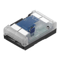
SBC PCD3 Series Manual (330 pages)
For PCD1/PCD2 and PCD3
Brand:
SBC
| Category:
I/O Systems
| Size: 13 MB
Table of Contents
Table of Contents
2
Content
7
Document Versions
7
Brands and Trademarks
7
Product Status of the I/O-Moduls
8
Input/Output (I/O) Modules for PCD1 and PCD2
10
General Informations
10
Overview
10
Power Consumption of PCD2 Input/Output Modules
16
Maximal Current Consumption from Base Units
17
Digital Input Modules
18
Pcd2.E11X, 8 Digital Inputs
19
PCD2.E160/161, 16 Digital Inputs, Ribbon Cable Connector
22
PCD2.E165/166, 16 Digital Inputs, Spring Terminal Connectors
25
Digital Input Modules, Electrically Isolated
27
PCD2.E500, 6 Digital Inputs for 115 - 230 VAC
27
PCD2.E610/611/613/616, 8 Digital Inputs, Electrically Isolated
30
7 Pcd2.B160 & Pcd3.B160
31
Hardware
31
Digital Output Modules
32
PCD2.A300, 6 Digital Outputs for 2 a each
33
PCD2.A400, 8 Digital Outputs for 0.5 a each
35
PCD2.A460, 16 Digital Outputs for 0.5 a Each, with Ribbon Connector
37
PCD2.A465, 16 Digital Outputs, for each 0.5 a
40
Digital Output Modules, Electrically Isolated
42
PCD2.A200, 4 Relays with Make Contacts, with Contact Protection
43
PCD2.A210, 4 Relays with Break Contacts, with Contact Protection
45
PCD2.A220, 6 Relays with Make Contacts, Without Contact Protection
47
PCD2.A250, 8 Relays with Make Contacts, Without Contact Protection
49
PCD2.A410, 8 Digital Outputs for 0.5 a Each, Electrically Isolated
51
Digital Combined Input and Output Modules
53
PCD2.B100, 2 Inputs + 2 Outputs + 4 Digital Inputs/Outputs (Selectable)
54
Multi-Functional Input/Output Modules
57
PCD2.G400 Multi-Functional Input/Output Module
57
PCD2.G410, Multi-Functional I/O Module with Elect. Isolated Digital I/O
59
Analogue Input Modules
61
Pcd2.W10X, Analogue Inputs, 4 Channels, 12 Bit Resolution
62
Pcd2.W11X, Analogue Inputs, 4 Channels, 12 Bit Resolution
65
Pcd2.W2X0, Analogue Inputs, 8 Channels, 10 Bit Resolution
70
Pcd2.W3X0, Analogue Inputs, 8 Channels, 12 Bit Resolution
76
Analogue Input Modules with Electricaly Isolation
82
Pcd2.W3X5, Analogue Inputs, 7 Channels, 12 Bit Resolution, Electrical Isolated
83
Analogue Output Modules
87
Pcd2.W4X0, Analogue Outputs, 4 Channels, 8 Bit Resolution
88
Pcd2.W6X0, Analogue Outputs, 4 Channels, 12 Bit Resolution
92
Analogue Output Modules with Electrically Isolation
96
Pcd2.W6X5, Analogue Outputs, 6 (4) Channels
97
10 Bit Resolution, Electrical Isolated
97
Analogue Input and Output Modules
101
Pcd2.W5X0, Analogue Inputs/Outputs, 2 + 2 Channels
102
12 Bit Resolution
102
Combined Analogue Input/Output Modules with Galvanic Isolation
106
PCD2.W525 Combined Analogue Input/Output Modules with Galvanic Isolation
107
Analogue Weighing Modules
115
Analogue Thermocouple Modules
116
Fast Counting Modules
117
PCD2.H100, Counting Module up to 20 Khz
118
PCD2.H110, General Purpose Counting / Measuring Module up to 100 Khz
123
SSI Interface Modules
125
PCD2.H150, SSI Interface Module for Absolute Encoder
126
Motion Control Modules for Stepper Motors
129
PCD2.H210, Motion Control Module for Stepper Motors
130
Motion Control Modules for Servo-Motors
133
Pcd2.H31X, Motion Control Module for Servo-Motors, 1-Axis Encoder
134
Pcd2.H32X, Motion Control Modules for Servo-Drives
138
Input/Output (I/O) Modules for PCD3
144
Introduction to I/O Modules
144
Connector Types
149
Current Consumption of the Modules
151
External Input Voltage
152
Example I/O Modules
153
Open the Module Housing
153
Digital Input Modules
154
PCD3.E110/111/112/116, 8 Digital Inputs
155
PCD3.E160/161, 16 Digital Inputs, Ribbon Cable Connector
157
PCD3.E165/166, 16 Digital Inputs, Cage Clamp Terminal Connectors
159
Digital Input Modules, Electrically Isolated from the I/O Bus
161
PCD3.E500, 6 Digital Inputs, Electrically Isolated from the I/O Bus
162
PCD3.E610/613, 8 Digital Inputs, Electrically Isolated from the I/O Bus
164
Digital Output Modules
166
PCD3.A300, 6 Digital Outputs for 2 a each
167
PCD3.A400, 8 Digital Outputs for 0.5 a each
169
PCD3.A460, 16 Digital Outputs for 0.5 a Each, with Ribbon Cable Connector
171
PCD3.A465, 16 Digital Outputs for 0.5 a each
173
Digital Output Modules, Electrically Isolated
175
PCD3.A200, 4 Relays with Make Contacts, with Contact Protection
176
PCD3.A210, 4 Relays with Break Contacts, with Contact Protection
178
PCD3.A220, 6 Relays with Make Contacts, Without Contact Protection
180
PCD3.A251, 8 Relays, 6 with Changeover Contacts
182
With Make Contacts
182
PCD3.A410, 8 Digital Outputs for 0.5 a Each, Electrically Isolated
184
Digital Output Modules for Manual Operation, Electrically Isolated
186
PCD3.A810, Digital Manual Control Module with 4 Relays
187
With Changeover, 2 with Make Contacts
187
PCD3.A860, Digital Light and Shade Module, with 2 Make Contacts
191
Digital Combined Input/Output Modules
197
PCD3.B100, Combined with 2 Inputs + 4 Digital I/Os
198
Technical Data on Inputs
198
Technical Data on Outputs
198
Analogue Input Modules
201
Pcd3.W2X0, Analogue Inputs, 8 Channels, 10 Bit Resolution
202
Pcd3.W3X0, Analogue Inputs, 8 Channels, 12 Bit Resolution
208
Analogue Input Modules, Electrically Isolated from the I/O Bus
216
Pcd3.W3X5, Analogue Inputs Electrically Isolated from the I/O Bus
217
Channels, 12 Bit Resolution
217
Analogue Output Modules
221
Pcd3.W4X0, Analogue Outputs, 4 Channels, 8 Bit Resolution
222
Pcd3.W6X0, Analogue Outputs, 4 Channels, 12 Bit Resolution
226
Analogue Output Modules, Electrically Isolated from the I/O Bus
231
Pcd3.W6X5, Analogue Outputs Electrically Isolated from the I/O Bus, 6(4) Channels, 10 Bit Resolution
232
Analogue Combined Input/Output Modules
236
PCD3.W500, Analogue Inputs/Outputs, 2 + 2 Channels
237
12 Bit Resolution
237
Analogue Combined Input/Output Modules, Electrically Isolated
241
PCD3.W525 Analogue Combined Input/Output Module with Electrical Isolation
242
Analogue Manual Control Modules
247
PCD3.W800, Analogue Manual Control Module with 4 Output Channels, 0
248
10 Bit Resolution
248
Weighing Modules
252
Pcd3.W7X0
252
General-Purpose Temperature Modules
253
Pcd3.W745
253
Counting and Motion Control I/O Modules
254
PCD3.H100, Counting Module up to 20 Khz
255
PCD3.H110, Counting Module up to 100 Khz
260
PCD3.H150, SSI Interface Module for Absolute Encoder
262
PCD3.H210, Motion Control Module for Stepper Motors
265
Pcd3.H31X, Motion Control Module for Servo-Motors, 1-Axis Encoder
268
Miscellaneous Modules
272
PCD3.S100 Workshop Simulator Unit
272
Output Wiring
279
Label Editor
280
Bloc Diagram
281
Configuration in PG5 Device Configurator
282
Media Mapping
284
Symbol Name & Description
284
Rddigitalio
284
Rdoutputerror
284
Wrdigitaloutput
284
Direct Input or Output Access in IL
285
Symbol Name & Description
285
Rd_Digital_Io_0To15
285
Mask_Rd_Digitaloutput_0To15
285
Rd_Output_Error_0To15
286
Rd_Firmware_Version
286
Rd_Module_Status
287
Wr_Digital_Output_0To15
287
Error PCD XOB 13
288
Pcd2.W380 & Pcd3.W380
290
PCD2/3.W380, 8 Analog Configurable Inputs
291
Module Overview
291
Inputs Connection
292
Specifications
293
General Data
293
Technical Data of Inputs
294
Input Wiring
296
Input Values Acquisition
297
Configurable Digital Filters
298
Out of Range Indication
298
Input Protections
299
Current Measuring Range
299
Protection Mode
300
LED Signalization
300
Block Diagram
301
Preparing the PLC System
301
Module in PG5 Environment
302
Preparing
302
Choosing the Module
302
Inputs Configuration
303
With Media Mapping
303
With Direct Access
303
Example of Linearization
308
Pcd2.G200
309
Overview PCD2.G200
310
Specifications
311
Resolution of the Analogue Inputs
313
Dip Switch Position
313
I/O Connection
314
Preparing the PLC System
314
Cpu Fw
314
Preparing
315
Device Configurator
315
Media Mapping
318
Example of Linearization
319
Appendix
320
Icons
320
Terms
321
Abbreviations
321
Hardware Watchdog
322
Sicherheitshinweise
323
Installation Direction and Relays Contact Protection
324
Installation Direction for Switching Extra Low Voltages
324
Installation Direction for Switching Low Voltages
325
Switching Inductive Loads
328
Relay Manufacturer's Information on RC Unit Dimensioning
328
Contact
330
Advertisement
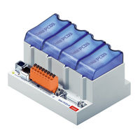
sbc PCD3 Series Manual (133 pages)
dual-valve pressure controllers
Brand:
sbc
| Category:
Controller
| Size: 16 MB
Table of Contents
Table of Contents
2
Content
5
Document Versions
5
Trademarks
6
1 Graphical Table of Contents
7
Graphic List of Contents
7
2 Orientation Guide
8
Introduction
8
Connection of Saia PCD ® Controllers to the Internet
8
Eplan ® Macros
8
Hardware Manual for PCD3 Series │ D Ocument 26-789 ENG19│ 2 018-06-29 0
8
Planning an Application
11
E/A Module Cabling
14
Cable Layout
14
Cable Routing
15
Overvoltage Protection for Long Distances or External Cables
15
Series Cabling
16
Addressing
17
Labeling of the Module Carriers and I/O Slot Modules
19
Module Carrier
19
I/O Slot Module
20
3 Pcd3.Mxxx0 Classic CPU and Module Carrier
24
System Overview
24
SBC S-Net Networking Concept
25
Saia PCD ® Web Server
26
General Technical Data
27
System Resources
29
Program Blocks
29
Value Range of the Number Types
29
Media
29
Pcd3 Cpu
30
Block Diagram Pcd3.Mxxx0
30
Pcd3.M3X20 / Pcd3.M3X30 and Pcd3.M5X40 / Pcd3.M6X40
31
Pcd3.Mxx60
33
Hardware and Firmware Versions of the Pcd3.Mxxx0
35
Extension with PCD3 Components
36
Module Carrier
38
The Module Carriers (LIO)
39
Calculation of the Possible Load
43
Module Carrier Connections
43
Installation of the CPU and Module Carrier
44
Mounting Position and Ambient Temperature
44
Assembly / Disassembly
44
Insertion of I/O Modules
45
Dimensions
46
Power Supply and Connection Plan
47
External Power Supply
47
Internal Power Supply
49
Internal Power Supply for more than One Module Carrier
49
Grounding and Connection Concept
51
Data Retention in the Event of Power Failure
52
Battery Module PCD3.R010 for Pcd3.M3Xxx
52
Operating States
54
Leds and Their Meaning
55
Operating Mode (Run/Stop)
56
Run/Stop Push-Button
56
Run/Stop Switch
57
Manual Control and Emergency Operation
58
Connections of the Pcd3.Mxxx0
60
Connections on Orange Terminal Block
61
Port 2)
61
Interrupt Inputs
62
Hardware Watchdog
64
Supply
66
Software Watchdog
67
Hardware Clock (Real Time Clock)
68
Storage Space on the PCD3
69
Storage Types in the Saia PCD ® Systems
69
Memory Management (PCD3 Without Integrated Μsd Flash Card)
71
Memory Management (PCD3 with Integrated Μsd Flash Card)
74
Memory Structure of the Saiapcd3 Systems
76
Optional Memory Upgrades
78
Overview
80
Storage Module PCD3.R600 for Flash Cards (FC)
83
SD Flash Memory Cards
87
Micro-SD Flash Memory Card PCD7.R-MSD1024
89
4 RIO (Remote Input Output) Head Stations
90
The RIO (Remote Input Output) Head Stations
90
Internal Power of the Pcd3.T76X Head Stations
90
Connections of the RIO Head Station Pcd3.T76X for 4 Modules
90
Meaning of the Connections
93
Power LED
94
Diagnosis Information of the Rios
95
LED Meaning
95
Diagnosis Module
97
Terminating Resistors of Profibus-DP or Profi S-Net Network
101
5 Communications Interfaces
102
General
102
Serial Interface Logs
102
Serial S-Net
105
Profi S-Net
105
Ether S-Net
105
Logs Implemented in the User Program
105
Onboard Interfaces
106
Summary Table
106
Connector (Port 0) as Communication Interface and as Programmer Connection (Only Pcd3.M5Xx0 / M6Xx0)
107
RS-232 Connector (Port 0) as Communication Interface and as Programmer Connection (Only Pcd3.M5Xx0 / M6Xx0)
107
RS-422 (Port 3)
109
S-Net / MPI (Port 10)
109
RS-485 / RS-422 (Port 3)
109
CAN (Port 10)
110
Profibus DP Master (Port 10)
110
USB PGU Interface for Programming Device Connection
111
Ethernet RJ-45 and Profibus
112
Profi S-Net/Dp Slave (Port 2)
113
Plug-In Interface Modules on I/O Slot 0
114
Overview Slot Interface Modules
114
Serial Interfaces on I/O Module Slot 0 (Port 1)
115
LIO and RIO
116
Interfaces of Pcd3.CXXX and Pcd3.Txxx
116
6 Input/Output (I/O) Modules
117
Configuration
118
CPU Processor Units
118
RIO - Remote Input Output Module Carrier Pcd3.T76X
118
Smart-RIO PCD3.T665 and PCD3.T666
118
8 Maintenance
122
Battery Change at the Pcd3.M5Xx0/M6Xx0
122
Battery Change at the Pcd3.M3Xx0 with PCD3.R010
122
A Appendix Symbols for Notes Etc
126
Mass Designation, Symbols and Meaning
126
Note Symbols
126
Definitions for the Serial Interfaces
127
A.2.2 Rs-485/422
128
Tty/Current Loop
130
Glossary
131
A.3 Glossary
131
Contact, Support and Repair Addresses
133
Advertisement
Related Products
SBC PCD2.M4160
SBC PCD2.M4560
SBC PCD2 Series
SBC PCD1.M135
SBC PCD2.M110
SBC PCD7.L790
SBC PCD2.M5 Series
SBC PCD2.M5540
SBC PCD7.LRL2-P5
SBC PCD7.LRL4-P5
sbc Categories
Cordless Telephone
Measuring Instruments
Telephone
Controller
I/O Systems
More sbc Manuals
Login
Sign In
OR
Sign in with Facebook
Sign in with Google
Upload manual
Upload from disk
Upload from URL