
SBC PCD2 Series Programmable Controller Manuals
Manuals and User Guides for SBC PCD2 Series Programmable Controller. We have 2 SBC PCD2 Series Programmable Controller manuals available for free PDF download: Manual
SBC PCD2 Series Manual (330 pages)
For PCD1/PCD2 and PCD3
Brand: SBC
|
Category: I/O Systems
|
Size: 13 MB
Table of Contents
-
Content7
-
-
-
Hardware31
-
-
-
-
-
Weighing Modules252
-
Pcd3.W7X0252
-
-
-
Pcd3.W745253
-
-
-
Output Wiring279
-
Label Editor280
-
Bloc Diagram281
-
Media Mapping284
-
-
Rddigitalio284
-
Rdoutputerror284
-
Wrdigitaloutput284
-
-
-
-
-
Module Overview291
-
Specifications293
-
General Data293
-
-
Input Wiring296
-
Protection Mode300
-
Block Diagram301
-
-
-
Preparing302
-
-
-
-
Pcd2.G200
309-
Specifications311
-
-
Cpu Fw314
-
Preparing315
-
Media Mapping318
-
-
Appendix
320-
Icons320
-
Terms321
-
Abbreviations321
-
Contact330
-
Advertisement
SBC PCD2 Series Manual (288 pages)
Brand: SBC
|
Category: Controller
|
Size: 10 MB
Table of Contents
-
2 Guidance
14 -
-
CPU Overview24
-
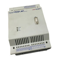
Pcd1.M1Xx24
-
-
Mounting35
-
Dimensions43
-
-
Basics52
-
-
-
-
-
-
Profibus121
-
-
7 Maintenance
270-
Order Codes285
Advertisement