Sign In
Upload
Manuals
Brands
Rohde & Schwarz Manuals
Inverter
SMATE200A
Rohde & Schwarz SMATE200A Manuals
Manuals and User Guides for Rohde & Schwarz SMATE200A. We have
2
Rohde & Schwarz SMATE200A manuals available for free PDF download: Operating Manual, Application Note
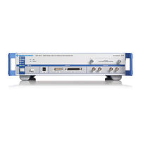
Rohde & Schwarz SMATE200A Operating Manual (809 pages)
Vector Signal Generator
Brand:
Rohde & Schwarz
| Category:
Laboratory Equipment
| Size: 9 MB
Table of Contents
Basic Safety Instructions
3
Customer Support
19
Table of Contents
20
Preface
32
Documentation Overview
32
Typographical Conventions
33
Preparing for Use
36
Front Panel Tour
36
Status Leds for Intrument State
37
Standby Leds and Standby Key
38
Status Leds for RF Outputs
38
Status LED for LXI
38
LAN Reset
38
Rear Panel Tour
38
Description of the Connectors
39
Putting into Operation
42
Unpacking and Checking the Instrument
44
Placing or Mounting the Instrument
44
Rack Mounting
45
Connecting the Instrument to the AC Supply
45
Starting the Instrument
46
Standby and Ready State
46
Start Display and Booting
47
Function Check
47
Default Settings
47
Shutting down the Instrument
49
Connecting External Accessories
49
Connecting USB Devices
50
Connecting a Monitor
51
Windows Operating System
51
Virus Protection
52
Service Packs and Updates
52
Login
53
Accessing the Start Menu
53
Setting up a Network (LAN) Connection
53
Connecting the Instrument to the Network
54
Assigning the IP Address
55
Using Computer Names
56
Changing the Windows Firewall Settings
56
Working with Directories
57
Remote Access Via an External Controller
57
Using a Web Browser for Remote Access
59
Remote Desktop Connection
60
Remote Access Via Ultr@Vnc
62
Using Virus-Protection Software
68
LXI Configuration
69
Firmware Update
71
Default State of the Network Settings
71
LXI Browser Interface
71
Browser Interface
71
LAN Configuration
72
Advanced LAN Configuration
73
Ping
74
Getting Started
76
Brief Introduction to the Instrument's Concept
76
Applications of the Instrument
78
Generation of Digitally Modulated Signal
78
Two Baseband Generators, One RF Path
79
One Baseband Path and Two RF Paths
80
Two RF Paths
81
Fully Equipped Two-Path Instrument
81
Baseband Section
82
Description of Individual Diagram Blocks of the Baseband Section
83
RF Section
84
Description of Individual Diagram Blocks of the RF Section
85
Example of Setup
86
Manual Operation
94
Legend of Manual Controls
94
Front Panel Key Emulation
96
On-Screen Keyboard
96
Key Features
97
Display
101
Settings Displayed in the Header Section
102
Status Information and Messages
102
Status Information
103
Messages
103
Volatile Messages
103
Permanent Messages
103
Info Window
104
Block Diagram
105
Function Blocks in the Block Diagram
105
Signal Flow and Input/Output Symbols in the Block Diagram
106
Winbar and Softkeys
107
Structure of the Dialogs
107
Graphical Display of Output Signal Characteristics
108
Accessing Dialogs
109
Keyboard Shortcuts
110
Setting Parameters
110
Working with the Cursor
111
Selecting a Control Element
112
Switching Parameters On/Off
112
Entering a Value
112
Working with Units
114
Selecting a Value from a List
114
Terminating Entries with Confirmation
115
Confirming Settings
115
Restoring the Previous Value
116
Editors
117
Working with List Editor
117
Working with Data Editor
118
Working with Control and Marker List Editor
120
How to Use the Help System
123
File Management
125
File Select Dialog
126
File Manager
128
Extensions for User Files
129
Instrument Function
132
Overview of Instrument Functions
132
General Instrument Settings
134
Overview of General Instrument Settings
134
Default Instrument Settings - Preset Key
135
General Configuration of Instrument - Setup Key
136
Internal Adjustments
136
Hardware Config
139
Software / Options
140
Manage License Keys
141
License Registration
142
Gui Update
142
NRP-Z Info/Update
143
Update
144
Selftest
144
Check Front Panel
145
Global Trigger/Clock/External Input Settings
145
Display/Keyboard Settings
147
User Marker / aux I/O Settings
148
Remote Channel Settings
150
LXI Status
151
Protection
152
Security
153
Security Password
155
Save/Recall
156
Factory Preset
156
Help
156
Switching to Manual Control - Local Key
157
Generating a Hard Copy of the Display
157
Hardcopy Dialog
158
Hardcopy Options
159
Messages - Info Key
162
Help System - Help Key
162
Storing and Loading Instrument Data - File Key
163
File Menu
164
Storing Instrument Settings
164
Loading Instrument Settings
166
File Manager
167
Graphical Display - Graphics
169
Graphics Settings Menu
170
Bar of Graphics Window
172
Signal Displays
174
I/Q Diagram
174
Vector Diagram
175
Constellation Diagram
176
Eye Diagram
177
CCDF Display
178
Power Spectrum
179
RF Signal and Analog Modulations - RF Block
180
Overview of RF Signal
180
RF Output
180
Overview of the RF Signal Settings
182
RF Frequency Settings
182
RF Frequency Vs. RF Output Frequency
183
Configuring RF Frequency
183
Frequency Menu
184
Phase Settings
186
Phase Menu
186
Phase Continuous Frequency Setting
186
Reference Oscillator
191
Reference Oscillator Dialog
191
Local Oscillator - lo Coupling
193
Phase Coherence
193
Typical Applications
194
LO Coupling Menu
195
NRP-Z Power Viewer
197
NRP-Z Power Viewer Settings
198
RF Level/Emf
204
Overview of RF Level
204
RF Level
205
Attenuator Settings
207
Power-On/Emf Settings
210
Automatic Level Control - ALC
210
Automatic Level Control Settings
212
User Correction
213
User Correction Menu
213
Filling the Correction List Automatically
218
Filling the Correction List with Power Sensor Measurement Data
220
Reverse Power Protection
222
Analog Modulations
222
Overview
222
Modulation Sources
223
Amplitude Modulation (AM)
224
Broadband Amplitude Modulation (BB-AM)
227
Frequency Modulation (FM)
228
Phase Modulation (Phim)
231
Pulse Modulation (PM)
234
LF Generator and LF Output - Mod Gen
236
Overview of LF Generator
236
LF Output
236
Sweep Mode
237
Overview
237
RF Frequency Sweep
238
RF Level Sweep
245
LF Frequency Sweep
252
List Mode
258
List Mode Extern Hop
258
List Mode Dialog
260
Filling the List Mode Data Automatically
267
I/Q Modulation - I/Q Mod Block
268
I/Q Modulator
269
I/Q Settings
270
General I/Q Mod Settings
271
Impairments
271
I/Q Swap and I/Q Wideband
278
Analog Wideband I/Q Input
279
Impairment of Digital I/Q Signal and Noise Generator - AWGN/IMP Block
281
Impairments
282
Impairment Settings Menu
282
AWGN - Noise Generator
293
AWGN Settings Dialog
294
Output of the Baseband Signal - I/Q out
301
I/Q out Settings Menu
301
Analog I/Q Output
302
I/Q Level - Info
305
Baseband Signal Level
306
Baseband Signal Level Measurement
307
Baseband Signal - Baseband Block
308
Working with the Baseband Signal
309
Data and Signal Sources in Baseband
315
Internal PRBS Data and Data Patterns
315
Internal Modulation Data from Lists
316
External Synchronous Modulation Data
317
Clock Signals
318
Synchronizing Data Signals and Clock Signals
319
Control Signals
322
Trigger Signals
324
Marker Output Signals
325
Digital Modulation - Custom Digital Modulation
325
Overview and Required Options
325
Modulation Types - Custom Digital Mod
326
Coding - Custom Digital Mod
330
Baseband Filter - Custom Digital Mod
333
Conflicting Settings - Custom Digital Mod
336
Custom Digital Mod User Interface
336
Data Source
339
Data List Editor
350
Arbitrary Waveform Generator ARB
366
ARB User Interface
369
Trigger/Marker/Clock Settings
374
Trigger Inhibit
379
Multi Segment Waveforms
392
Multi Segment Waveform Sequencing
398
Multi Carrier Waveforms
402
Multi Carrier Continuous Wave
414
Multi Carrier CW User Interface
414
Carrier Setup
416
Number of Carriers
416
Carrier Spacing
416
Clock Settings
426
Clock Multiplier
427
Remote Control Basics
430
Remote Control Interfaces and Protocols
430
VISA Libraries
431
Messages
431
Instrument Responses
432
LAN Interface
432
Hislip Protocol
433
Protocol
434
Socket Communication
434
LAN Interface Messages
434
USB Interface
435
GPIB Interface (IEC/IEEE Bus Interface)
435
GPIB Interface Messages
436
GPIB Instrument Address
437
Starting a Remote Control Session
437
Switching to Remote Control
438
Returning to Manual Operation
439
Examples
439
Remote Control over GPIB
439
Remote Control over LAN Using VXI-11 Protocol
440
Configuring the Controller
440
Remote Control over LAN Using Socket Communication
444
SCPI Command Structure
450
Syntax for Common Commands
451
Syntax for Device-Specific Commands
451
Special Characters
454
SCPI Parameters
454
Character Strings
456
Overview of Syntax Elements
457
Structure of a Command Line
457
Responses to Queries
458
Command Sequence and Synchronization
459
Preventing Overlapping Execution
460
Status Reporting System
462
Hierarchy of Status Registers
462
Structure of a SCPI Status Register
464
Contents of the Status Registers
465
Status Byte (STB) and Service Request Enable Register (SRE)
465
IST Flag and Parallel Poll Enable Register (PPE)
466
Event Status Register (ESR) and Event Status Enable Register (ESE)
466
Application of the Status Reporting System
467
Service Request
468
Serial Poll
468
Parallel Poll
468
Query of an Instrument Status
469
Error Queue
469
Reset Values of the Status Reporting System
469
General Programming Recommendations
470
Remote Control Commands
472
Common Commands
472
Cal
472
Cls
472
Ese
473
Esr
473
Idn
473
Ist
473
Opc
474
Opt
474
Pcb
474
Pre
474
Psc
474
Rcl
475
Rst
475
Sav
475
Sre
475
Preset Commands
476
Stb
476
Trg
476
Tst
476
Wai
476
R&S Signal Generator Waveform and List Format
478
Tag Description
479
TYPE: Magic, XXXXXXXX
479
CLOCK: Frequency
480
COMMENT: String
481
COPYRIGHT: String
481
DATA BITLENGTH: Bitlength
481
DATA LIST-Length: #D0D1
482
DATE: Yyyy-MM-DD;Hh:MM:ss
482
CONTROL LENGTH: Controllength
482
LEVEL OFFS: Rmsoffset_Db,Peakoffset_Db
482
SAMPLES: Samples
483
[TRACE] LIST [#]: Pos0:Val0;Pos1:Val1
484
WAVEFORM-Length: #I0Q0I1Q1
484
MWV_SEGMENT_COUNT: Numofseg
486
MWV_SEGMENT_LENGTH: Samplesseg0, Samplesseg1
486
Mwv_Segment_Start
487
Samplestartoffsetseg0, Samplestartoffsetseg1
487
MWV_SEGMENT_CLOCK_MODE: Mode
487
MWV_SEGMENT_CLOCK: Clockseg0, Clockseg1
488
Mwv_Segment_Level_Offs
489
Rmsoffset_Dbseg0, Peakoffset_Dbseg0
489
Mwv_Segment_Files
489
Filenameseg0.Wv", "Filenameseg1.Wv
489
Mwv_Segmentx_Comment: Text
489
CONTROL LIST WIDTH4-Length: #M0M1
489
Creating a Waveform Manually
490
Creating an ASCII C-List Manually
494
Calibration Subsystem
495
C Alibration: a LL[: M Easure]
495
Calibration<Hw>:Fmoffset[:Measure]
496
Calibration<Hw>:Frequency[:Measure]
496
Calibration<Hw>:Iqmodulator:full
496
Calibration<Hw>:Iqmodulator:local
496
Clock Subsystem
497
Calibration<Hw>:Level[:Measure]
497
C Alibration<Hw>: L Evel: S Tate
497
C Alibration<Hw>: L Evel: H Accuracy[: S Tate]
497
Diagnostic Subsystem
499
Display Subsystem
501
Format Subsystem
501
Hcopy Subsystem
503
Kboard Subsystem
511
Mmemory Subsystem
512
File Naming Conventions
512
Extensions for User Files
513
Examples
515
Remote Control Commands
516
Output Subsystem
522
Sense, READ and Initiate Subsystems
527
I Nitiate<Ch>[: P Ower]: C Ontinuous
528
R Ead<Ch>[: P Ower]
528
Sense<Ch>[: P Ower]: C Orrection: S Pdevice: S Tate
529
Sense<Ch>[: P Ower]: D Isplay: P Ermanent: S Tate
529
Sense<Ch>[: P Ower]: D Isplay: P Ermanent: P Riority
530
Sense<Ch>[:Power]:Filter:length:auto
530
Sense<Ch>[: P Ower]: F Ilter: L Ength[: U SER]
530
Sense<Ch>[: P Ower]: F Ilter: N Sratio
531
Sense<Ch>[: P Ower]: F Ilter: N Sratio: M Time
531
Sense<Ch>[:Power]:Filter:sonce
531
Sense<Ch>[: P Ower]: F Ilter: T YPE
532
Sense<Ch>[: P Ower]: F Requency
532
Sense<Ch>[: P Ower]: O Ffset
533
Sense<Ch>[: P Ower]: O Ffset: S Tate
533
Sense<Ch>[:Power]:Snumber
533
Sense<Ch>[: P Ower]: S Ource
533
Sense<Ch>[:Power]:Status[:Device]
534
Sense<Ch>[:Power]:Sversion
534
Sense<Ch>[:Power]:Type
534
Source Subsystem
535
Sense<Ch>[:Power]:Zero
535
Sense<Ch>: U NIT[: P Ower]
535
Source:am Subsystem
536
Source:awgn Subsystem
539
[: S Ource<Hw>]: a WGN: B Rate
539
[: S Ource<Hw>]: a WGN: B Width
540
[:Source<Hw>]:Awgn:bwidth:noise
540
[: S Ource<Hw>]: a WGN: B Width: R Atio
541
[: S Ource<Hw>]: a WGN: C Nratio
541
[: S Ource<Hw>]: a WGN: D ISP: M ODE
541
[: S Ource<Hw>]: a WGN: E Nratio
542
[:Source<Hw>]:Awgn:frequency:result
542
[: S Ource<Hw>]: a WGN: F Requency: T Arget
543
[: S Ource<Hw>]: a WGN: M ODE
543
[: S Ource<Hw>]: a WGN: P Ower: C Arrier
543
[: S Ource<Hw>]: a WGN: P Ower: M ODE
544
[: S Ource<Hw>]: a WGN: P Ower: N Oise
544
[:Source<Hw>]:Awgn:power:noise:total
545
[: S Ource<Hw>]: a WGN: P Ower: R Mode
545
[:Source<Hw>]:Awgn:power:sum
546
[:Source<Hw>]:Awgn:power:sum:pep
546
[: S Ource<Hw>]: a WGN: S Tate
546
Source:bb Subsystem
547
Source:bb Subsystem General Commands
547
Source:bb:arb Subsystem
549
[:Source<Hw>]:Bb:arb:mcarrier:create
573
[: S Ource<Hw>]: B B: a RB: M Carrier: E DIT: C Arrier: D Elay: S TEP
573
[: S Ource<Hw>]: B B: a RB: M Carrier: E DIT: C Arrier: D Elay[: S Tart]
574
[:Source<Hw>]:Bb:arb:mcarrier:edit:carrier:execute
574
[: S Ource<Hw>]: B B: a RB: M Carrier: E DIT: C Arrier: F ILE
575
[: S Ource<Hw>]: B B: a RB: M Carrier: E DIT: C Arrier: P Hase: S TEP
575
[: S Ource<Hw>]: B B: a RB: M Carrier: E DIT: C Arrier: P Hase[: S Tart]
575
[: S Ource<Hw>]: B B: a RB: M Carrier: E DIT: C Arrier: P Ower: S TEP
576
[: S Ource<Hw>]: B B: a RB: M Carrier: E DIT: C Arrier: P Ower[: S Tart]
576
[: S Ource<Hw>]: B B: a RB: M Carrier: E DIT: C Arrier: S Tart
576
[: S Ource<Hw>]: B B: a RB: M Carrier: E DIT: C Arrier: S TOP
576
[: S Ource<Hw>]: B B: a RB: M Carrier: E DIT: C Arrier: S Tate
577
[: S Ource<Hw>]: B B: a RB: M Carrier: O File
577
[:Source<Hw>]:Bb:arb:mcarrier:preset
577
[:Source<Hw>]:Bb:arb:mcarrier:samples
577
[:Source<Hw>]:Bb:arb:mcarrier:setting:catalog
578
[: S Ource<Hw>]: B B: a RB: M Carrier: S Etting: L OAD
578
[: S Ource<Hw>]: B B: a RB: M Carrier: S Etting: S Tore
578
[: S Ource<Hw>]: B B: a RB: M Carrier: S Etting: S Tore: F AST
578
[: S Ource<Hw>]: B B: a RB: M Carrier: T IME
579
[: S Ource<Hw>]: B B: a RB: M Carrier: T IME: M ODE
579
Source:bb:DM Subsystem
594
Trigger Settings
600
List of Commands
618
[:Source<Hw>]:Bb:DM:dlist:tag
620
[: S Ource<Hw>]: B B: D M: C List: D ATA
621
[: S Ource<Hw>]: B B: D M: C List: D Elete
622
[:Source<Hw>]:Bb:DM:clist:points
622
[: S Ource<Hw>]: B B: D M: C List: S Elect
622
[: S Ource<Hw>]: B B: D M: D List: D ATA
623
[: S Ource<Hw>]: B B: D M: D List: D Elete
624
[: S Ource<Hw>]: B B: D M: D List: P Oints
624
[: S Ource<Hw>]: B B: D M: D List: S Elect
625
Source:bb:graphics Subsystem
630
Source:bb:impairment Subsystem
632
Source:bb:mccw Subsystem
641
[: S Ource<Hw>]: B B: M CCW: S Tate
641
[:Source<Hw>]:Bb:mccw:preset
642
[: S Ource<Hw>]: B B: M CCW: C Arrier: C Ount
642
[: S Ource<Hw>]: B B: M CCW: C Arrier: L IST: P Hase
642
[: S Ource<Hw>]: B B: M CCW: C Arrier: L IST: P Ower
643
[: S Ource<Hw>]: B B: M CCW: C Arrier: L IST: S Tate
643
[: S Ource<Hw>]: B B: M CCW: C Arrier: P Hase
643
[: S Ource<Hw>]: B B: M CCW: C Arrier: P Ower
644
[: S Ource<Hw>]: B B: M CCW: C Arrier: S Pacing
644
[: S Ource<Hw>]: B B: M CCW: C Arrier: S Tate
645
[: S Ource<Hw>]: B B: M CCW: C Factor
645
[: S Ource<Hw>]: B B: M CCW: C Factor: M ODE
645
[:Source<Hw>]:Bb:mccw:clock
646
[:Source<Hw>]:Bb:mccw:edit:carrier:execute
646
[: S Ource<Hw>]: B B: M CCW: E DIT: C Arrier: P Hase: S TEP
647
[: S Ource<Hw>]: B B: M CCW: E DIT: C Arrier: P Hase[: S Tart]
647
[: S Ource<Hw>]: B B: M CCW: E DIT: C Arrier: P Ower: S TEP
648
[: S Ource<Hw>]: B B: M CCW: E DIT: C Arrier: P Ower[: S Tart]
648
[: S Ource<Hw>]: B B: M CCW: E DIT: C Arrier: S Tart
648
[: S Ource<Hw>]: B B: M CCW: E DIT: C Arrier: S Tate
649
[: S Ource<Hw>]: B B: M CCW: E DIT: C Arrier: S TOP
649
Source:bb:measurement Subsystem
660
Source:bb:power Subsystem
663
Source:correction Subsystem
664
Source:fm Subsystem
673
Source:frequency Subsystem
676
Source:input Subsystem
686
Source:iq Subsystem
689
Source:iq:output Subsystem
693
Analog I/Q Outputs
693
Source:lfoutput Subsystem
698
Source:list Subsystem
706
Source:modulation Subsystem
720
Source:path Subsystem
721
Source:phase Subsystem
721
Source:pm Subsystem
722
Source:power Subsystem
725
Source:pulm Subsystem
734
Source:roscillator Subsystem
736
Source:sweep Subsystem
738
Status Subsystem
746
System Subsystem
750
TEST Subsystem
758
Trigger Subsystem
759
UNIT Subsystem
764
Maintenance
766
Storing and Packing
766
Error Messages
768
Status Information
768
Status Information Displayed between the Frequency and Level Fields
768
Status Information Displayed to the Left of the Info Line
769
Status Information Displayed in the Info Line
770
Error Messages
771
Volatile Messages
771
Permanent Messages
771
SCPI-Error Messages
772
Device-Specific Error Messages
772
A Hardware Interfaces
776
GPIB Bus Interface
776
Interface Functions
777
AUX I/O Connector
777
Monitor Connector (MONITOR)
779
Digital I/O Interface
779
Hardware Interfaces
781
List of Commands
782
Index
797
Advertisement
Rohde & Schwarz SMATE200A Application Note (23 pages)
Brand:
Rohde & Schwarz
| Category:
Inverter
| Size: 1 MB
Table of Contents
Table of Contents
2
1 Introduction
3
2 Functional Description
4
3 Setup
5
Providing WLAN Access for the T&M Instrument
6
WLAN Connection Via WLAN Router
6
WLAN Connection Via WLAN USB Adapter
7
Installation for Windows XP T&M Instruments
8
Installation for Windows 7 T&M Instruments
11
Installing the RDP Client Application on the Tablet
13
Establishing the WLAN Connection on the Tablet
13
Establishing the RDP Connection
14
4 Operation
17
Locking the Tablet's Screen Rotation Function
17
Controlling the T&M Instrument Via RDP
17
Operation Via Virtual Mouse and Keyboard
17
Control Elements of the T&M Instrument Views
18
Starting a Firmware Application on a CMW
20
Disconnecting from the T&M Instrument
20
5 Related Documents
22
6 References
22
Advertisement
Related Products
Rohde & Schwarz SMF-B2
Rohde & Schwarz SMF-B27
Rohde & Schwarz SMF-B32/-B34
Rohde & Schwarz SMF-B82
Rohde & Schwarz SMF-B84
Rohde & Schwarz SMF-B85
Rohde & Schwarz SMF-B122
Rohde & Schwarz SMF-B144
Rohde & Schwarz SMF-K3
Rohde & Schwarz SMF-K23
Rohde & Schwarz Categories
Measuring Instruments
Test Equipment
Portable Generator
Power Supply
Accessories
More Rohde & Schwarz Manuals
Login
Sign In
OR
Sign in with Facebook
Sign in with Google
Upload manual
Upload from disk
Upload from URL