Sign In
Upload
Manuals
Brands
Rockwell Automation Manuals
I/O Systems
Allen-Bradley POINT Guard
Rockwell Automation Allen-Bradley POINT Guard Manuals
Manuals and User Guides for Rockwell Automation Allen-Bradley POINT Guard. We have
1
Rockwell Automation Allen-Bradley POINT Guard manual available for free PDF download: User Manual
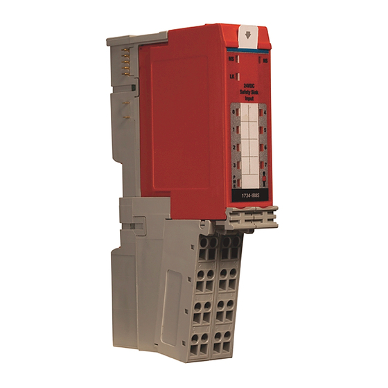
Rockwell Automation Allen-Bradley POINT Guard User Manual (212 pages)
I/O Safety Modules
Brand:
Rockwell Automation
| Category:
I/O Systems
| Size: 11.07 MB
Table of Contents
Table of Contents
5
Preface
11
Studio 5000 Environment
11
Access Product Release Notes
12
Terminology
12
Additional Resources
13
Chapter 1
15
POINT Guard I/O Overview
15
Understand Suitability for Use
15
POINT Guard I/O Modules in CIP Safety Systems
17
1734-IB8S Digital Input Module Features
18
1734-OB8S Safety Digital Output Module Features
18
1734-IE4S Safety Analog Input Module Features
19
Programming Requirements
19
CIP Safety Architectures
20
Safety Precautions
17
Installing and Replacing Modules
17
Safety Application Requirements
21
Chapter 2 Safe States
23
POINT Guard Digital I/O Modules
23
POINT Guard I/O Analog Input Module
24
Safety Inputs, Safety Outputs, and Safety Data
23
Safety Inputs (1734-IB8S)
24
Using a Test Output with a Safety Input
24
Single-Channel Mode
26
Dual-Channel Mode and Discrepancy Time
27
Dual-Channel, Equivalent
28
Dual-Channels, Complementary
29
Safety Input Fault Recovery
30
Input Delays
30
Safety Analog Inputs (1734-IE4S)
31
Input Range
31
Scaling
31
Digital Input Filter
32
Sensor Power Supply
32
Channel Offset
33
Process Alarms
33
Using a Single-Channel Sensor
34
Dual-Channel Equivalent Mode
35
Tachometer Mode
36
Safety Outputs (1734-OB8S)
39
Safety Output with Test Pulse
39
Dual-Channel Mode
39
Safety Output Fault Recovery
40
Muting Lamp Operation (1734-IB8S)
40
I/O Status Data
42
Digital I/O Status Data
42
Analog I/O Status Data
43
Choosing a Power Supply
45
And Modules in a System Power Supply Examples
46
Chapter 3 Power Supply Examples
46
Example 1: Isolating Field Power Segments
47
Example 2: POINT Guard I/O Used with AC I/O Modules
47
Placing Series a Digital and Analog Modules
48
Placing Series B Digital Modules
48
Chapter 4 Install the Module Precautions
52
North American Hazardous Location Approval
53
Environment and Enclosure
53
Preventing Electrostatic Discharge
54
Precautions
52
European Hazardous Location Approval
52
Mount the Module
54
Install the Mounting Base
54
Connect the Module to the Mounting Base
55
Connect the Removable Terminal Block
56
Remove a Mounting Base
57
Wire Modules
58
Terminal Layout
59
Connection Details
60
Wiring Examples
62
Emergency Stop Dual-Channel Devices
62
Single-Channel Safety Contactor
63
Dual-Channel Safety Contactors
64
Safety Analog Input Wiring
65
Setting up the Module
73
Add and Configure the Ethernet Bridge Module
74
Chapter 5
74
Add and Configure the 1734 Ethernet Adapter
75
Add and Configure Safety Digital Input Modules
77
Add the Safety Digital Input Module
77
Configure the Safety Digital Inputs
82
Configure the Test Outputs
85
Add and Configure Safety Digital Output Modules
86
Add the Safety Digital Output Module
86
Configure the Safety Digital Outputs
90
Add and Configure Safety Analog Input Modules
91
Add the Safety Analog Input Module
91
Configure the Safety Analog Input Channel Operation
94
Configure the Safety Analog Inputs
95
Configure Safety Analog Input Alarms (Optional)
96
Rockwell Automation Publication 1734-UM013J-EN-P - July
96
Configure Tachometer Operation
98
Values and States of Tags
100
Configure Safety Connections
102
Configuration Ownership
103
Modules
104
Saving and Downloading the Module Configuration
104
Using Controlflash Software to Update POINT Guard I/O
104
Before You Begin
105
Chapter 6
106
Set the Node Address
106
Smartguard Controller Set the Node Address
106
Auto-Addressing with a 1734-PDN Adapter
108
Set up Your Devicenet Network
109
Configure the POINT Guard I/O Modules
110
Configure Digital Safety Inputs and Test Outputs
110
Configure Digital Safety Outputs
113
Configure Safety Analog Inputs
114
Configure the Smartguard Controller
119
Set up the Input and Output Connections
119
Complete the Set up of the Smartguard Controller
123
Save and Download Module Configuration
124
Configure the Module in Rsnetworx for Devicenet Software
125
Add the POINT Guard I/O Module to the Controller Project
126
Chapter 7
126
Complete the Safety Configuration
129
Download the Devicenet Network Configuration
131
Verify Your Devicenet Safety Configuration
131
Determine if Devices Can be Verified
132
Select Devices to Verify
133
Review the Safety Device Verification Reports
134
Lock Safety Devices
135
The Safety Network Number
137
Chapter 8
138
Manually Setting the Safety Network Number
138
Resetting a Module to Out-Of-Box Condition
139
By Using the Logix Designer Application
139
By Using Rsnetworx for Devicenet Software
140
Network
141
Replacement with 'Configure Only When no Safety Signature
141
Exists' Enabled
141
Replacement with 'Configure Always' Enabled
145
Replacing a Module in a Guardlogix System on an Ethernet/Ip
141
Controller on a Devicenet Network
147
Replacing a Module When Using a Smartguard or Guardlogix
147
Appendix A
152
Configuration Lock
152
Module
152
Network Status
152
1734-IB8S Safety Input Status
153
1734-IE4S Safety Analog Input Status
153
1734-IE4S Sensor Power
153
Power
153
1734-OB8S Safety Output Status
154
Message Instructions
155
Appendix B
156
Configure the Message Instruction
156
Class, Instance, and Attribute Data for I/O Modules
157
Appendix C Technical Specifications for Series a Modules
161
Safety Digital Input Module Specifications
161
Safety Digital Output Module Specifications
163
Safety Analog Input Module Specifications
164
Technical Specifications for Series B Modules
173
Safety Digital Input Module Specifications
173
Safety Digital Output Module Specifications
176
Environmental Specifications
177
Certifications
179
Legislations and Standards
179
Appendix D
182
Series a Safety Data
182
Series B Safety Data
184
Appendix E
188
Appendix E
189
Appendix E
190
Appendix F
191
Input Assemblies
191
Analog Input Assemblies
192
Output Assemblies
192
Configuration Assemblies
194
Using Data from Modules Configured Via the Generic Profile
200
1734-UM013F-EN-P, June 2012
201
1734-UM013G-EN-P, August 2012
201
1734-UM013H-EN-P, August 2012
201
1734-UM013I-EN-P, May 2013
201
Appendix G
201
Rockwell Automation Publication 1734-UM013J-EN-P - July
201
1734-UM013C-EN-P, August 2010
202
1734-UM013D-EN-P, September 2011
202
1734-UM013E-EN-P, March 2012
202
1734-UM013A-EN-P, February 2009
203
1734-UM013B-EN-P, June 2009
203
Advertisement
Advertisement
Related Products
Rockwell Automation Allen-Bradley POINT I/O DeviceLogix
Rockwell Automation Allen-Bradley ArmorPOINT I/O DeviceLogix
Rockwell Automation Allen-Bradley DeviceNet Base RTD
Rockwell Automation Allen-Bradley Thermocouple CompactBlock LDX I/O
Rockwell Automation Allen-Bradley Compact 5000 Series
Rockwell Automation Allen-Bradley 5069 Series
Rockwell Automation Allen-Bradley B Series
Rockwell Automation Allen-Bradley POINT I/O C Series
Rockwell Automation Allen-Bradley ArmorBlock 5000 Series
Rockwell Automation AB Quality Allen-Bradley SLC 500
Rockwell Automation Categories
Controller
Control Unit
Power Supply
DC Drives
Industrial Equipment
More Rockwell Automation Manuals
Login
Sign In
OR
Sign in with Facebook
Sign in with Google
Upload manual
Upload from disk
Upload from URL