Sign In
Upload
Manuals
Brands
Ricoh Manuals
All in One Printer
Aficio 2035
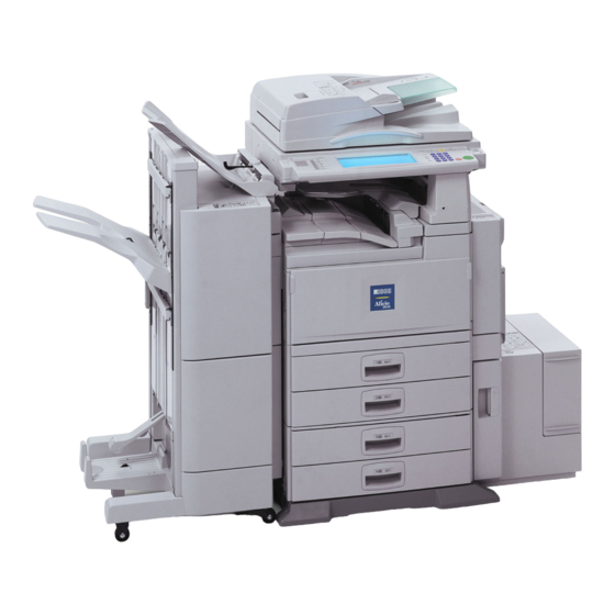
Ricoh Aficio 2035 Manuals
Manuals and User Guides for Ricoh Aficio 2035. We have
3
Ricoh Aficio 2035 manuals available for free PDF download: Service Manual, Operating Instructions Manual, Manual
Ricoh Aficio 2035 Service Manual (868 pages)
Brand:
Ricoh
| Category:
All in One Printer
| Size: 41.32 MB
Table of Contents
Table of Contents
13
Service Manual
1
Bridge Unit B
22
Important Safety Notices
23
Laser Safety
24
Installation
29
1 Installation Procedure
31
Installation Requirements
31
Environment
32
Machine Level
32
Minimum Space Requirements
33
Power Requirements
35
Installation Flow Chart
36
Main Machine Installation
37
Accessory Check
37
Installation Procedure
38
Development Unit and PCU
39
Toner Bottle
42
Paper Trays
43
Initialize TD Sensor and Developer
45
Set Paper Size for Paper Trays
46
Electrical Total Counter
47
Exposure Glass Cleaner
47
HDD Caution Decal
47
Paper Tray Unit Installation (B542)
48
Accessory Check
48
Paper Tray Unit Installation Procedure
49
Cabinet Installation Procedure
53
1-Bin Tray Unit Installation (B544)
56
Accessory Check
56
1-Bin Tray Installation Procedure
57
Bridge Unit Installation (B538)
63
Accessory Check
63
Bridge Unit Installation Procedure
64
Two-Tray Finisher Installation (B545)
66
Accessory Check
66
Two-Tray Finisher Installation Procedure
67
Punch Unit Installation (B377)
70
Accessory Check
70
Punch Unit Installation Procedure
71
Ardf Installation (B541)
74
Accessory Check
74
Ardf Installation Procedure
75
Ardf Skew Adjustment
78
Lct Installation (B543)
79
Accessory Check
79
Lct Installation Procedure
80
Platen Cover Installation (G329)
82
Booklet Finisher Installation (B546)
83
Accessory Check
83
Booklet Finisher Installation Procedure
84
1000 Sheet Finisher (B408)
90
1000 Sheet Finisher Installation Procedure
90
Check All Connections
93
Key Counter Installation (A674)
94
Anti-Condensation Heater
96
Tray Heater
98
Tray Heater (Optional Paper Tray Unit)
98
Tray Heater (Optional Paper Tray Unit)
99
Optional User Account Enhancement Unit (B443)
100
Preventive Maintenance
101
2 Preventive Maintenance Schedule
103
Pm Table
103
Troubleshooting
199
Service Tables
228
Detailed Section Descriptions
335
Replacement and Adjustment
107
General Cautions
109
Laser Unit
109
Used Toner
109
Lubricants
110
Special Tools
110
Special Tools and Lubricants
110
Symbols Used in Text
110
Duplex Unit
111
Front Door
111
Upper Right Cover
112
By-Pass Tray
113
Rear Covers
114
Rear Lower Cover
114
Rear Upper Cover
114
Left Covers
115
Left Upper Cover
115
Ardf
116
Scanner Unit
116
Exposure Glass
117
Scanner Exterior Panels/Operation Panel
118
Lens Block/Sbu Assembly
119
Original Size Sensors
120
Exposure Lamp
121
Scanner Hp Sensor/Platen Cover Sensor
122
Scanner Motor
123
Lamp Stabilizer and Scanner Motor Drive Board
124
Scanner Wire
125
Caution Decal Locations
129
Laser Unit
129
Laser Unit
130
Polygon Mirror Motor
132
Laser Synchronization Detector
133
Ld Unit
133
Laser Beam Pitch Adjustment
134
Pcu
135
Photoconductor Unit (Pcu)
135
Drum
136
Pick-Off Pawl Position Adjustment
138
Pick-Off Pawls
138
Charge Roller and Cleaning Roller
139
Drum Cleaning Blade 2
140
Drum Cleaning Blade 1
141
Development
142
Development Unit
142
Development Filter
143
Development Roller
143
Developer
144
Td Sensor
146
Transfer Belt Unit
147
Transfer Unit
147
Transfer Belt
148
Transfer Belt Cleaning Blade and Toner Overflow Sensor
149
Paper Feed
150
Pick-Up, Separation, and Feed Rollers
150
Lower Right Cover
151
Relay/Upper Paper Feed and Lower Paper Feed Clutches
152
Upper Paper Feed Unit for Tray 1
153
Lower Paper Feed Unit for Tray 2
154
Paper End/Paper Height/Relay Sensors
155
Registration Sensor
156
Tray Lift Motor
158
Feed/Development Motor
159
Fusing Unit
160
Fusing Unit Removal
160
Fusing Unit Exit Guide
161
Hot Roller Strippers
161
Fusing Lamps
162
Thermistors and Thermostats
164
Fusing Roller/Pressure Roller
165
Fusing Unit Side Fan
167
Fusing Unit Corner Fan
169
Idle Roller Dust Blade
170
Cover Replacement
171
By-Pass Separation Roller Replacement
173
Paper End Sensor and Pick-Up Solenoid
174
Paper Size Sensor Board Replacement
175
By-Pass Table Removal
176
Paper Feed Clutch Replacement
177
Registration Roller Dust Blade
178
Duplex Cover Removal
179
Duplex Entrance Sensor Replacement
180
Duplex Exit Sensor Replacement
181
Drive Area
182
Main Motor
183
Toner Supply Motor
184
High Voltage Power Supply
185
Printed Circuit Boards
185
Iob Dip Switch Settings (Sw)
187
Bicu Board
188
Hard Disk, Controller Board
189
Copy Adjustments: Printing/Scanning
190
Registration - Leading Edge/Side-To-Side
190
Blank Margin
191
Main Scan Magnification
191
Parallelogram Image Adjustment
192
Registration: Platen Mode
193
Adf Image Adjustment
194
Touch Screen Calibration
195
Troubleshooting
197
Service Call Conditions
199
Sc Code Descriptions
200
Electrical Component Defects
222
Blown Fuse Conditions
223
Test Points
224
Service Tables
225
Service Program Mode
227
Sp Mode Button Summary
228
Selecting the Program Number
229
Service Table Key
230
Sp1-XXX: Feed
231
Sp2-XXX: Drum
234
Sp3-XXX: Process
243
Sp4-XXX: Scanner
244
Sp5-XXX: Mode
267
Sp6-XXX: Peripherals
285
Sp7-XXX: Data Log
287
Test Pattern Printing: Sp
296
Test Pattern Table: Sp2-902-3 Printing Test Patterns
297
Input Check
298
Main Machine Input Check: Sp
298
Ardf Input Check: Sp
302
Output Check
303
Ardf Output Check: Sp
305
Smc Print out Lists: Sp
305
Nip Band Width Adjustment: Sp
309
Memory Clear: Sp
310
Software Reset
311
System Settings and Copy Setting Reset
312
Software Download
314
Uploading Nvram Data (Sp)
315
Uploading/Downloading Nvram Data
315
Downloading Nvram Data (Sp)
316
Detailed Self-Diagnostic Mode
318
Executing Detailed Self-Diagnosis
318
How to Use up Mode
320
System Settings
320
Up Mode Initial Screen: User Tools/Counter Display
320
User Program Mode
320
Copier/Document Server Features
321
Printer, Facsimile, Scanner Settings
321
Dip Switches
323
Capturing Debugging Information
324
Using the Debug Log
324
Setting the Timing for Debug Log Acquisition
325
Selecting a Module for Retrieval
326
Recording Errors Manually
328
Retrieving the Debug Log
328
Detailed Section Descriptions
331
Paper Path
335
Drive Layout
336
Block Diagram
337
Board Structure
337
Copy Process Overview
342
Image Transfer
343
Book Mode
345
Scanner Drive
345
Original Size Detection in Platen Mode
346
Image Processing
348
Sbu (Sensor Board Unit)
349
Auto Image Density (Ads)
350
Ipu (Image Processing Unit)
351
Image Processing Modes
352
Summary of Image Processing Functions
354
Image Processing Steps and Related Sp Modes
355
Text/Photo Mode
356
Photo Mode
357
Pale (Low-Density Mode)
358
Generation Copy Mode
359
Background Erase
361
Independent Dot Erase
362
Line Width Correction
363
Interactive Sp Codes
364
Pale, Generation Mode Filter
370
Photo Mode Smoothing for Dithering
371
Photo Mode Image Quality
372
Vertical Black Line Correction
373
Density Settings
374
Practical Application of Sp Modes
376
Solving Problems
376
Recommended Settings for Mtf Filters
377
Laser Exposure
379
Dual Beam Writing
381
Laser Beam Pitch Change Mechanism
382
Ld Safety Switches
383
Drum Pawls
385
Drum Toner Seals
385
Drum Cleaning
386
Drum Charge
387
Charge Roller Voltage Correction
388
Correction for Environmental Conditions
388
Correction for Paper Width and Thickness
389
Drum Charge Roller Cleaning
390
ID Sensor Pattern Production Timing
390
Developer Mixing
392
Development Bias
393
Toner Bottle Replenishment Mechanism
394
Toner Supply
394
Toner Supply Mechanism
395
Sensor Control Mode
396
Toner Density Control
396
Toner Near End/End Detection
397
Toner End Recovery
398
Toner Supply with Abnormal Sensors
398
Drum Cleaning and Toner Recycling
399
Paper Feed Drive
401
Paper Lift
402
Paper End Detection
403
Paper Registration
404
Paper Size Detection
405
By-Pass Tray Operation
407
By-Pass Paper Size Detection
408
Duplex Drive Layout
410
Duplex Basic Operation
411
Duplex Unit Feed in and Exit Mechanism
412
Inversion and Exit
412
Image Transfer and Paper Separation
413
Transfer Belt Unit Contact Mechanism
414
Transfer Belt Charge
416
Transfer Belt Cleaning Mechanism
419
Toner Scatter Prevention
420
Image Fusing and Paper Exit
421
Fusing Drive
422
Fusing Drive Release Mechanism
422
Exit Guide Plate and De-Curler Rollers
423
Fusing Entrance Guide Shift Mechanism
423
Pressure Roller
424
Cleaning Mechanism
425
Hot Roller Stripper Cleaning
426
Fusing Temperature Control
428
Temperature Control
429
Fusing Idling Temperature
430
Cpm down for Thick Paper
431
Cooling and Overheat Protection
432
Energy Saver Modes
433
Energy Saver Mode
434
Entering the Energy Saver Mode
434
Return to Stand-By Mode
434
What Happens in Energy Saver Mode
434
Auto off Mode
435
Returning to Stand-By Mode
435
Specifications
437
General Specifications
439
Power Consumption
440
Optional Equipment
443
Booklet Finisher
449
Booklet Finisher B546
451
1 Overall Machine Information
453
Mechanical Component Layout
453
2 Detailed Descriptions
454
A4/LT Sideways or Shorter
454
Junction Gate Mechanism
454
Longer than A4 Sideways
454
Shift Tray Mode
454
Booklet Stitch Mode
455
Proof Tray Mode
455
Pre-Stack Mechanism
456
Paper Shift Mechanism
457
Paper Positioning Mechanism
458
Drive
459
Front and Rear Stapling
459
Movement
459
Stapler Unit Movement Mechanism
459
Tow-Position Stapling
459
Stapler
460
Shift Tray Mechanism
461
Booklet Unit Gate Mechanism
462
Relay Roller and Positioning Plate Mechanism
464
Positioning Roller Mechanism
465
Booklet Unit Jogger Movement Mechanism
466
Booklet Stapler Unit
467
Paper Folder Mechanism
468
3 Replacement and Adjustment
470
Removal
470
Upper Door
470
Lower Rear Cover
471
Upper Rear Cover
471
Top Cover
472
Upper Inner Cover
472
Shift Tray Unit
473
Lower Shift Guide
474
Upper Shift Guide
474
Exit Unit
475
Buffer Roller Unit
476
Stapler
477
Finisher Board
478
Booklet Unit
479
Folder Rollers
481
Folder Plate
484
Removal
484
Reinstalling
485
Booklet Stapler Unit
486
Removal
486
Adjustment
487
Booklet Board
489
Positioning Plate Unit
489
1St and 2Nd Booklet Unit Gates
490
Adjustment
491
Shift Tray Height
491
Jogger Fence Position
492
Stapling Position
493
Booklet Stapling Position
494
Auto Reverse Document Feeder
497
Auto Reverse Document Feeder B541
499
B541
501
Replacement and Adjustment
501
Covers
501
Original Feed Unit
502
Original Pick-Up Roller
502
Original Feed Belt
503
Skew Correction/Interval/ Registration/Original Width Sensors
504
Original Length Sensors
505
Separation Roller
505
Inverter /Original Set Sensors
506
Pick-Up Motor/Original Stopper Hp Sensor/Pick-Up Hp Sensor
506
Scanner Motor and Inverter Motor
507
Feed Motor, Skew Correction Roller Clutch
508
Exit Sensor
509
Stamp Solenoid
509
Controller Board
509
2 Troubleshooting
510
Timing Charts
510
A4(S)/Lt(S) Single-Side Original Mode
510
A4(S)/Lt(S) Double-Sided Original Mode
511
Jam Detection
512
3 Service Tables
513
Dip Switches
513
Fuses
513
Test Points
513
4 Detailed Description
514
Main Components
514
Drive Layout
515
Basic Mechanism
516
Original Size Detection
516
Mixed Original Size Mode
518
Original Feed-In Mechanism
519
Pick and Separation
519
Original Skew Correction
520
Reducing the Interval between
520
Original Transport and Exit
521
Single-Sided Originals
521
Sm B541
521
Double-Sided Originals
522
Stamp
523
Df70 Software Modification History
524
Large Capacity Tray
525
Large Capacity Tray B543
527
1 Overall Machine Information
529
Specifications
529
Mechanical Component Layout
530
Electrical Component Layout
531
Electrical Component Description
532
Drive Layout
533
2 Detailed Descriptions
534
Paper Feed Mechanism
534
TRAY LIFT and Paper HEIGHT DETECTION MECHANISM
535
Tray Lifting Conditions
535
Tray Lowering Conditions
535
Tray Unit Slide Mechanism
536
3 Service Tables
537
Dip Switches
537
Fuses
537
Switches
537
Test Points
537
4 Replacement and Adjustment
538
Cover Replacement
538
Front Cover
538
Rear Cover
538
Right Lower Cover
538
Tray Cover
538
Upper Cover
538
Paper Feed Roller
539
PAPER FEED, SEPARATION, and PICK-UP Rollers
539
Pick-Up Roller
539
Roller Replacement
539
Separation Roller
539
Paper End Sensor
540
Tray Lift and Paper End Sensor Replacement
540
Tray Lift Sensor
540
Relay Sensor Replacement
541
Side Fence Position Change
542
Paper Tray Unit B542
545
Mechanical Component Layout
548
Paper Height Detection
556
1 Replacement and Adjustment
558
Cover Replacement
558
Rear Cover
558
Right Cover
558
Paper Feed, Separation, and Pick-Up Rollers
559
Paper Feed Roller
559
Pick-Up Roller
559
Separation Roller
559
Roller Replacement
559
Tray Motor Replacement
560
PAPER FEED and RELAY Clutch REPLACEMENT
561
Paper FEED UNIT REPLACEMENT
562
Lower Paper Feed Unit
563
Upper Paper Feed Unit
563
Paper End, Tray Lift, and Relay Sensor Replacement
564
Paper End Sensor
564
Relay Sensor
564
Tray Lift Sensor
564
1-Bin Tray B544
567
1 Overall Machine Information
569
4 Specifications
569
Mechanical Component and Drive Layout
570
Electrical Component Description
571
Electrical Component Layout
571
2 Detailed Descriptions
572
Basic Operation
572
3 Replacement and Adjustment
573
Cover Removal
573
Front Cover
573
Rear Cover
573
Upper Cover
573
Paper Sensor Replacement
574
Entrance and Paper Limit Sensor Replacement
575
Entrance Sensor
575
Paper Limit Sensor
575
Sheet Finisher
577
1000-Sheet Finisher B408
579
1 Replacement and Adjustment
581
Main Pcb
581
Stapler Unit
582
Motors
583
Shift Motor
583
Stapler Motor
583
Lower Transport Motor
584
Upper Transport Motor and Exit Motor
584
Motors and Sensors
585
Preparation
585
Stack Height Sensor
586
Stapler Tray Paper Sensor
586
Lower Tray Lift Motor
587
Stack Feed-Out Motor
587
2 Troubleshooting
588
Jam Detection
588
3 Service Tables
589
Dip Switch Settings
589
4 Detailed Descriptions
590
General Layout
590
Electrical Component Layout
591
Electrical Component Description
593
Drive Layout
595
Junction Gates
596
Sort/Stack Mode
596
Staple Mode
596
Upper Tray Mode
596
Upper Tray
597
Lower Tray Up/Down Mechanisms
598
Paper Shift Mechanism
599
Jogger Unit Paper Positioning Mechanism
600
Exit Guide Plate
601
Stapler Mechanism
602
Stapler Unit Movement Mechanism
603
Paper Feed-Out Mechanism
604
Two-Tray Finisher B545
607
1 Replacement and Adjustment
609
Covers
609
External Covers
609
Inner Cover
609
Positioning Roller
610
Tray 1 Exit Sensor
610
Entrance Sensor/Stapler Tray Entrance Sensor
611
Stapler Tray
611
Upper Stack Height Sensors/Tray 1 Upper Limit Switch
612
Exit Guide Plate Motor
613
Lift Motors
613
Lower Exit Sensor
615
Lower Stack Height Sensors
616
Tray 2 Shunt Position Sensor
616
Stapler Rotation Hp Sensor
617
Stapler Unit
617
Tray 1 Interior
618
Tray 1 Covers
618
Back Fence Lock Clutch
619
Tray 1 Shift Motor
619
Tray Shift Sensors and Tray Release Sensor
619
Finisher Main Board
620
Punch Hole Position Adjustment
620
2 Troubleshooting
621
A4(S)/Lt(S) Shift Mode with Punch - Tray 1
621
Timing Charts
621
A4(S)/Lt(S) Shift Mode with Punch - Tray 2
622
A4(S)/Lt(S) Staple Mode with Punch
623
Jam Detection
624
3 Service Tables
625
Dip Switch Settings
625
Fuses
625
Test Points
625
4 Detailed Descriptions
626
General Layout
626
Drive Layout
627
Junction Gates
628
Tray 1 (Upper Tray)
629
Tray Shift Mechanisms
629
Tray Shifting
629
Tray 2 (Lower Tray)
630
Introduction
631
Normal and Sort/Stack Modes
631
Staple Mode
632
Tray 1 Release Mechanism
633
Tray 2
635
Pre-Stack Mechanism
636
Horizontal Paper Alignment
637
Jogger Unit Paper Positioning Mechanism
637
Vertical Paper Alignment
637
Side-To-Side Movement
638
Stapler Mechanism
638
Stapler Movement
638
Stapler Rotation
638
Stapler
639
Feed out and Transport
640
Punch Drive Mechanism
641
Punch Unit (Optional)
641
Punch Waste Collection
642
Bridge Unit
643
Bridge Unit B538
645
1 Overall Information
647
Mechanical Component Layout
647
Electrical Component Layout
648
Drive Layout
649
2 Detailed Section Descriptions
650
Original Size Detection
650
Pick-Up and Separation
652
Original Transport and Exit Mechanism
653
Stamp
654
Timing Charts
655
A3, Stamp Mode
656
Jam Detection
657
Overall Electrical Circuit
658
Free Run
659
Procedure
659
3 Replacement and Adjustment
660
Exterior Covers
660
Front Cover
660
Original Entrance Guide
660
Original Table
660
Rear Cover
660
Df Feed Cover
661
Feed Unit
661
Separation Roller
661
Feed Belt
662
Pick-Up Roller
662
Original Sensors (Width, Length, Trailing Edge)
663
Original Set Sensor
664
Transport Motor
664
Df Cover Open Sensor/Feed Clutch/Rom/Df Drive Board
665
Exterior
665
Feed Clutch
665
Feed Cover Open Sensor
665
Rom
665
Pick-Up Solenoid
666
Registration Sensor
666
Stamp Solenoid
667
Printer Option B548
671
Installation
673
Accessory Check
673
Controller Board and Hdd Removal
674
Printer Controller Installation
675
Paper Limit Sensor Installation
676
Paper Sensor Installation
677
Operation Panel Keytops
678
Printer Installation Procedure
674
Postscript 3 (G354-17)
679
Mb Memory (G331)
680
Nib (B525)
681
Ieee 1394 Firewire (G336)
682
Usb 2.0 (B525)
684
Ieee 802.11B B515 (Wireless Lan)
686
Bluetooth (G354-04)
690
Check All Connections
692
Troubleshooting
693
Controller Errors
693
Service Tables
694
Scanner Program Mode Table
694
Scanner Service Mode
694
Details
702
Ethernet Board
702
Ethernet Board Layout
702
Ethernet Board Operation
703
Ieee1394 Board (Firewire)
704
Overview
704
Specifications
706
Usb
706
Pin Assignment
707
Usb Connectors
707
Related SP Mode
708
Remarks about Usb
708
Ieee 802.11B (Wireless Lan)
709
LED Indicators
709
Specifications
709
Ad Hoc Mode
710
Infrastructure Mode
710
Transmission Modes
710
Security Features
711
Using the SSID in Ad Hoc Mode
711
Channel Settings
712
Communication Status
712
Wireless Lan Troubleshooting Notes
712
Troubleshooting Procedure
713
Bluetooth
714
Specifications
714
Bluetooth Profiles
715
Bluetooth Security Features
715
Specifications
716
Led Indicators
716
System Components
716
Printer Specifications
717
Usb Specifications
717
Ieee 802.11B Specifications
718
Scanner Specifications
718
Printer
719
Printer Drivers
719
Software Accessories
719
Utility Software
719
Scanner
720
Scanner Driver
720
Scanner Utilities
720
Fax Option B547
723
Installation
727
Cautions and Warnings
727
Procedure Flowchart
728
Fax Option Type
729
Fax Option Type 2045
731
G3 Interface Unit Type 2045
736
Jbig A892
740
Troubleshooting
742
Error Codes
742
Error Codes for the Isdn Option
750
D-Channel Layer Management
751
D-Channel Link Layer
751
B-Channel Link Layer
752
D-Channel Network Layer
752
B-Channel Network Layer
753
Transport Layer
753
Session Layer
754
Document Layer
755
Presentation Layer
755
Fax Sc Codes
756
Overview
756
Sc1201
756
Sc1207
756
Fax Sc Code Table
757
Isdn Test Function
758
Back-To-Back Test
759
Service Tables
760
Entering and Exiting SP Mode
760
Service Program Mode
760
Service Program Mode Operation
760
SP2-XXX (RAM Data)
762
SP3-XXX (Tel Line Settings)
762
SP4-XXX (ROM Versions)
763
SP5-XXX (Initializing)
764
SP6-XXX (Reports)
764
SP7-XXX (Test Modes)
766
Bit Switches
767
System Switches
767
Fax Switches
777
Printer Switches
782
Communication Switches
787
G3-1 Switches
796
G3-2 Switches
804
G3-3 Switches
809
G4 Internal Switches
810
G4 to G3 Fallback
816
G4 Parameter Switches
817
Ncu Parameters
820
Dedicated Transmission Parameters
830
Programming Procedure
830
Parameters
831
Service Ram Addresses
835
Detailed Section Descriptions
844
Overview
844
Boards
845
Fcu
845
Ncu (Us)
847
Ncu (Europe/Asia)
848
Sg3 Board
849
Sig4 Board
850
Transmission
851
Video Data Path
851
Immediate Transmission
852
Jbig Transmission
852
Reception
854
Fax Communication Features
856
Personal/Information/Transfer Boxes
856
Multi-Port
859
Document Server
860
Lan Fax Driver
861
Address Book
863
Address Book Backup
863
Overview of Data Backup
863
SP Modes
865
Specifications
866
Capabilities of Programmable Items
867
Machine Configuration
868
Advertisement
Ricoh Aficio 2035 Operating Instructions Manual (132 pages)
Copy Reference
Brand:
Ricoh
| Category:
Copier
| Size: 2.92 MB
Table of Contents
What You Can Do with this Machine
7
Table of Contents
10
How to Read this Manual
13
Machine Types
14
Functions that Require Options
15
Control Panel
16
Display Panel
18
Placing Originals
19
Originals
19
Sizes and Weights of Recommended Originals
19
Sizes Detectable by the Auto Paper Select
20
Missing Image Area
21
Placing Originals
22
Original Orientation
22
Placing Originals on the Exposure Glass
23
Placing Originals in the Auto Document Feeder
24
Copying
27
Basic Procedure
27
Interrupt Copy
28
Original Beeper
28
Job Preset
29
Copying from the Bypass Tray
30
Copier Functions
33
Adjusting Image Density
33
Selecting Original Type Setting
34
Selecting Copy Paper
35
Preset Reduce/Enlarge
38
Zoom
39
Auto Reduce/Enlarge
40
Size Magnification
40
Directional Magnification (%)
41
Directional Size Magnification (MM)
42
Sort
43
Stack
46
Staple
47
Punch
53
Duplex
55
One-Sided Combine
57
Two-Sided Combine
59
Series Copies
60
Booklet/Magazine
62
Image Repeat
64
Double Copies
65
Centring
66
Positive/Negative
67
Erase
67
Margin Adjustment
70
Background Numbering
71
Preset Stamp
71
User Stamp
72
Date Stamp
75
Page Numbering
77
Covers
80
Designate
81
Slip Sheets
83
Storing Data in the Document Server
84
Programs
85
Storing a Program
85
Changing a Stored Program
86
Deleting a Program
86
Recalling a Program
86
Troubleshooting
87
If Your Machine Does Not Operate as You Want
87
When a Message Is Displayed
87
If You Cannot Make Clear Copies
89
If You Cannot Make Copies as You Want
90
When Memory Is Full
93
User Tools (Copier/Document Server Features)
95
User Tools Menu (Copier/Document Server Features)
95
Accessing User Tools (Copier/Document Server Features)
101
Quitting User Tools
101
General Features 1 / 4
102
General Features
104
General Features
105
Reproduction Ratio
106
Reproduction Ratio 2 / 2
106
Edit
107
Edit 2 / 2
107
Stamp
110
Input/Output
113
Specifications
115
Combination Chart
115
Supplementary Information
116
Index
128
Ricoh Aficio 2035 Manual (12 pages)
SAP Printing
Brand:
Ricoh
| Category:
Printer
| Size: 0.06 MB
Table of Contents
Table of Contents
2
1 The Concept
3
The Sap Systems Supported
3
The Device Models Supported
3
The Family of Provided Device Types
3
2 The Device Types
6
ZA00 (and ZA04)
6
ZA01 (and ZA05)
6
Zb00
7
3 The Documentation
8
Volume 1 = Readme
8
Volume 2 : [Device Type] = Device Type Specific Information
8
Volume 2B = Barcode and Ocr Text Printing
8
Volume 3 : [Device Class] = Device-Specific Information
8
4 Appendices
9
Appendix D: Device Models Supported
9
Advertisement
Advertisement
Related Products
Ricoh SP 203SFNw
Ricoh 2051 - Aficio B/W Laser
Ricoh 2018
Ricoh Aficio 2018D
Ricoh Aficio 2022
Ricoh 2045 - Type Print Server
Ricoh Aficio 2075 SP
Ricoh Aficio 2060 SP
Ricoh Aficio 200
Ricoh AFICIO2060 - Aficio 2060 B/W Laser
Ricoh Categories
All in One Printer
Printer
Digital Camera
Copier
Printer Accessories
More Ricoh Manuals
Login
Sign In
OR
Sign in with Facebook
Sign in with Google
Upload manual
Upload from disk
Upload from URL