Sign In
Upload
Manuals
Brands
REXROTH Manuals
Controller
ECODRIVE03
REXROTH ECODRIVE03 Drive Controllers Manuals
Manuals and User Guides for REXROTH ECODRIVE03 Drive Controllers. We have
1
REXROTH ECODRIVE03 Drive Controllers manual available for free PDF download: Troubleshooting Manual
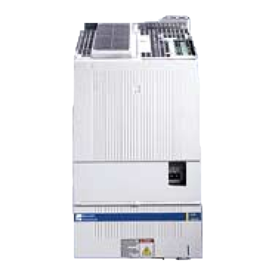
REXROTH ECODRIVE03 Troubleshooting Manual (130 pages)
Drive for General Automation with SERCOS and Parallel Interface
Brand:
REXROTH
| Category:
Controller
| Size: 1.21 MB
Table of Contents
Table of Contents
5
1 Diagnostic Message Descriptions
13
Overview of the Diagnostic Message Descriptions
13
Diagnostic Message Types
13
Construction of a Diagnostic Message
13
H1-Display
14
2 Important Directions for Use
17
Appropriate Use
17
Introduction
17
Areas of Use and Application
18
Inappropriate Use
18
3 Safety Instructions for Electric Drives and Controls
19
Introduction
19
Explanations
19
Hazards by Improper Use
20
General Information
21
Protection against Contact with Electrical Parts
23
Protection against Electric Shock by Protective Low Voltage (PELV)
24
Protection against Dangerous Movements
25
Protection against Magnetic and Electromagnetic Fields During Operation and Mounting
27
Protection against Contact with Hot Parts
28
3.10 Protection During Handling and Mounting
28
3.11 Battery Safety
29
3.12 Protection against Pressurized Systems
29
4 Description of Diagnostic Messages F
31
Error Diagnostic Messages F
31
F205 Cam Shaft Invalid
32
F207 Switching to Uninitialized Operation Mode
32
F208 UL the Motor Type Has Changed
32
F209 PL Load Parameter Default Values
33
F217 Blower Not Connected
33
F218 Amplifier Overtemperature Shutdown
33
F219 Motor Overtemperature Shutdown
34
F220 Braking Resistor Overload Shutdown
34
F221 Motor Temp. Surveillance Defective
35
F223 Error During Initialisation of the Parking Axis
35
F224 Maximum Braking Time Exceeded
36
F226 Undervoltage in Power Section
36
F228 Excessive Deviation
36
F229 Encoder 1 Failure: Quadrant Error
37
F230 Max. Signal Frequency of Encoder 1 Exceeded
37
F236 Excessive Position Feedback Difference
38
F237 Excessive Position Command Difference
39
F242 Encoder 2 Failure: Signal Amplitude Wrong
39
F245 Encoder 2 Failure: Quadrant Error
40
F246 Max Signal Frequency of Encoder 2 Exceeded
41
F248 Low Battery Voltage
41
F249 Master Drive Encoder Failure: Signal too Small
42
F250 Overflow of Target Position Preset Memory
42
F252 Master Drive Encoder Failure: Quadrant Error
43
F253 Incr. Encoder Emulator: Pulse Frequency too High
43
F260 Command Current Limit Shutoff
43
F262 External Short at Status Outputs
43
F267 Erroneous Internal Hardware Synchronization
44
F269 Error During Release of the Motor Holding Brake
44
F276 Absolute Encoder out of Allowed Window
45
F277 Current Measurement Trim Wrong
45
F281 Mains Fault
46
F386 no Ready Signal from Supply Module
46
F401 Double MST Failure Shutdown
46
F402 Double MDT Failure Shutdown
46
F403 Invalid Communication Phase Shutdown
47
F404 Error During Phase Progression
47
F405 Error During Phase Regression
47
F406 Phase Switching Without Ready Signal
48
F407 Error During Initialization of Master Communication
48
F408 Fatal Error of the Interface Card
48
F434 Emergency-Stop
48
F629 Positive Travel Limit Exceeded
49
F630 Negative Travel Limit Exceeded
49
F634 Emergency-Stop
50
F643 Positive Travel Limit Switch Detected
50
F644 Negative Travel Limit Switch Detected
51
F811 Commutation Offset Could Not be Determined
51
F812 Motion Range Exceeded During Commutation
52
F822 Encoder 1 Failure: Signal Amplitude Wrong
52
F828 Safe Halt While Drive Activated
54
F842 Encoder 2 Failure: Signal Amplitude Wrong
54
F845 Encoder 2 Failure: Quadrant Error
54
F860 Overcurrent: Short in Power Stage
54
F870 +24Volt DC Error
54
F873 Power Supply Driver Stages Fault
55
F878 Velocity Loop Error
55
F879 Velocity Limit S-0-0091 Exceeded
56
Warning Diagnostic Messages E
57
E217 Cooling Fan too Slow
58
E221 Warning Motor Temp. Surveillance Defective
58
E225 Motor Overload
58
E226 Undervoltage in Power Section
59
E247 Interpolation Velocity = 0
59
E248 Interpolation Acceleration = 0
59
E249 Positioning Velocity >= S-0-0091
60
E250 Drive Overtemp. Prewarning
61
E251 Motor Overtemp. Prewarning
61
E252 Braking Resistor Overload Prewarning
61
E253 Target Position out of Travel Range
62
E254 Not Homed
62
E255 Feedrate-Override S-0-0108 = 0
63
E256 Torque Limit = 0
63
E257 Continuous Current Limit Active
63
E258 Selected Process Block Is Not Programmed
64
E259 Command Velocity Limit Active
64
E260 Command Current Limit Active
64
E261 Continuous Current Limit Pre-Warning
65
E263 Velocity Command Value > Limit S-0-0091
65
E264 Target Position out of Num. Range
66
E269 Brake Torque too Low
66
E281 Mains Fault
66
E386 no Ready Signal from Supply Module
67
E401 Error in the Parameter Channel
67
E402 Error in the Cyclic Data Channel
67
E408 Invalid Addressing of MDT-Data Container a
68
E409 Invalid Addressing of AT-Data Container a
68
E410 Slave Not Scanned or Address 0
68
E825 Overvoltage in Power Stage
68
E826 Undervoltage in Power Section
69
E829 Positive Position Limit Exceeded
69
E830 Negative Position Limit Exceeded
70
E831 Position Limit Reached During Jog
70
E834 Emergency-Stop
70
E835 Quick Stop with Probe Detection Is Active
71
E843 Positive Limit Switch Activated
71
E844 Negative Limit Switch Activated
71
E881 Mains Fault
72
E886 no Ready Signal from Supply Module
72
5 Description of Diagnostic Messages B
73
Command Diagnostic Messages B
73
B100 Command Release Motor Holding Brake
74
B101 Command Not Enabled
74
B200 Brake Check Command
74
B201 Brake Check Only with Drive Enable
74
B202 Error During Abrasion of the Brake
74
B203 Brake Torque too Low
75
C100 Communication Phase 3 Transition Check
75
C101 Invalid Communication Parameter (S-0-0021)
75
C102 Limit Error Communication Parameter (S-0-0021)
75
C104 Config. IDN for MDT Not Configurable
76
C105 Configurated Length > Max. Length for MDT
76
C106 Config. IDN for at Not Configurable
76
C107 Configurated Length > Max. Length for at
77
C108 Time Slot Parameter > Sercos Cycle Time
77
C109 Position of Data Record in MDT (S-0-0009) Even
77
C110 Length of MDT (S-0-0010) Odd
78
C111 ID9 + Record Length - 1 > Length MDT (S-0-0010)
78
C112 Tncyc (S-0-0001) or Tscyc (S-0-0002) Error
78
C113 Relation Tncyc (S-0-0001) to Tscyc (S-0-0002) Error
79
C114 T4 > Tscyc (S-0-0002) - T4Min (S-0-0005)
79
C115 T2 too Small
79
C118 Order of MDT Configuration Wrong
79
C200 Communication Phase 4 Transition Check
80
C201 Invalid Parameter(S) (->S-0-0022)
80
C202 Parameter Limit Error (->S-0-0022)
80
C203 Parameter Calculation Error (->S-0-0022)
81
C204 Motor Type P-0-4014 Incorrect
81
C210 Feedback 2 Required (->S-0-0022)
81
C211 Invalid Feedback Data (->S-0-0022)
82
C212 Invalid Amplifier Data (->S-0-0022)
82
C213 Position Data Scaling Error
82
C214 Velocity Data Scaling Error
83
C215 Acceleration Data Scaling Error
83
C216 Torque/Force Data Scaling Error
84
C217 Feedback1 Data Reading Error
84
C218 Feedback 2 Data Reading Error
85
C220 Feedback 1 Initializing Error
85
C221 Feedback 2 Initializing Error
86
C223 Input Value for Max. Range too High
86
C227 Modulo Range Error
86
C228 Controller Type S-0-0140 Wrong
87
C234 Encoder Combination Not Possible
87
C235 Load-Side Motor Encoder with Inductance Motor Only
87
ECODRIVE03-SGP-03VRS Contents
88
C236 Feedback 1 Required (P-0-0074)
88
C238 Wrong Function of Encoder 2 (->S-0-0022)
88
C241 Binary Encoder Resolution Necessary
88
C300 Command Set Absolute Measuring
88
C302 Absolute Measuring System Not Installed
88
C400 Switching to Parameter Mode
89
C401 Drive Active, Switching Not Allowed
89
C402 Only Allowed Without Master
89
C500 Reset Class 1 Diagnostic, Error Reset
89
C600 Drive Controlled Homing Procedure Command
90
C601 Homing Only Possible with Drive Enable
90
C602 Distance Home Switch - Reference Mark Erroneous
90
C604 Homing of Absolute Encoder Not Possible
90
C606 Reference Mark Not Detected
91
C700 Basic Load
91
C702 Default Parameters Not Available
91
C703 Default Parameters Invalid
92
C704 Parameters Not Copyable
92
C800 Default Parameter Load
92
C801 Parameter Default Value Erroneous (-> S-0-0021)
93
C802 Locked with Password
93
D300 Command Adjust Commutation
93
D301 Drive Not Ready for Commutation Command
93
D302 Torque/Force too Small to Move
93
D303 Drive in Control at Start of Command
94
D304 Error in Offset Calculation
94
D305 Drive Enable Refused
94
D306 Power Is off
94
D307 Drive Does Not Move
94
D308 no Adjustment with Asynchronous Motor
94
D309 Proceed to Phase 4
95
D310 Input Master Password
95
D311 Commutation Offset Could Not be Determined
95
D312 Motion Range Exceeded During Commutation
95
D400 Positive Stop Drive Procedure Command
96
D401 ZKL1-Error at Command Start
96
D500 Command Get Mark Position
96
D501 Incremental Encoder Required
97
D600 Cancel Reference Point Procedure Command
97
D700 Parking Axis Command
97
D701 Parking Axis Only While Drive Is Disabled
97
D800 Command Measuring Wheel Mode
97
D801 Measuring Wheel Operation Not Possible
98
D900 Command Automatic Loop Tuning
98
D901 Start Requires Drive Enable
98
D902 Motor Feedback Data Not Valid
99
D903 Inertia Detection Failed
99
D904 Gain Adjustment Failed
99
D905 Travel Range Invalid, P-0-0166 & P-0-0167
100
D906 Travel Range Exceeded
100
Status Diagnostic Messages
101
A001 Communication Phase 1
101
A002 Communication Phase 2
101
A003 Communication Phase 3
102
A010 Drive HALT
102
A012 Control and Power Sections Ready for Operation
103
A013 Ready for Power on
103
A014 Safe Halt
103
A100 Drive in TORQUE Control
103
A101 Drive in VELOCITY Control
103
A102 Position Mode with Encoder 1
103
A103 Position Mode with Encoder 2
104
A104 Position Mode Lagless, Encoder 1
104
A105 Position Control Lagless, Feedback 2
104
A106 Drive Controlled Interpolation, Encoder 1
104
A107 Drive Controlled Interpolation, Encoder 2
104
A108 Drive Controlled Interpolation, Lagless, Encoder 1
105
A109 Drive Controlled Interpolation, Lagless, Encoder 2
105
A110 Velocity Synchronization, Virtual Master Drive
105
A111 Velocity Synchronization, Real Master Drive
105
A112 Phase Synchronization, Encoder 1, Virtual Master Drive
106
A113 Phase Synchronization, Encoder 2, Virtual Master Drive
106
A114 Phase Synchronization, Encoder 1, Real Master Drive
106
A116 Phase Synchr. Lagless, Encoder 1, Virtual Master Drive
106
A117 Phase Synchr. Lagless, Encoder 2, Virtual Master Drive
107
A118 Phase Synchr. Lagless, Encoder 1, Real Master Drive
107
A128 Cam Shaft, Encoder 1, Virtual Master Drive
107
A129 Cam Shaft, Encoder 2, Virtual Master Drive
107
A130 Cam Shaft, Encoder 1, Real Master Drive
107
A132 Cam Shaft, Lagless, Encoder 1, Virt. Master Drive
108
A133 Cam Shaft, Lagless, Encoder 2, Virt. Master Drive
108
A134 Cam Shaft, Lagless, Encoder 1, Real Master Drive
108
A150 Drive Controlled Positioning, Encoder 1
109
A151 Drive Controlled Positioning, Encoder 1, Lagless
109
A153 Drive Controlled Positioning, Encoder 2, Lagless
110
A203 Stepper Position Mode
110
A204 Stepper Position Mode, Lagless
110
A206 Process Block Mode, Encoder 1
111
A207 Process Block Mode Lagless, Encoder 1
111
A208 JOG Mode Positive
111
A210 Process Block Mode, Encoder 2
111
A211 Process Block Mode Lagless, Encoder 2
111
A218 JOG Mode Negative
112
A400 Automatic Drive Check and Adjustment
112
A401 Drive Deceleration to Standstill
112
A800 Unknown Operating Mode
112
Diagnostic Messages for Basic Initialization and after Fatal System Errors
113
Diagnostic Message Display: -0
113
Diagnostic Message Display: -1
113
Diagnostic Message Display: -2
113
Diagnostic Message Display: -3
113
Diagnostic Message Display: -4
113
Diagnostic Message Display: -5
113
Diagnostic Message Display: -6
113
Diagnostic Message Display
113
(2 Dots)
113
Diagnostic Message Display: E1
114
Diagnostic Message Display: E2
114
Diagnostic Message Display: E3
114
Diagnostic Message Display: E4
114
Diagnostic Message Display: E5
114
Operation Status
115
6 Index
117
7 Service & Support
123
Helpdesk
123
Service-Hotline
123
Internet
123
Vor der Kontaktaufnahme
123
Kundenbetreuungsstellen - Sales & Service Facilities
124
Advertisement
Advertisement
Related Products
Rexroth EcoDrive 03
REXROTH EcoDrive Cs
REXROTH ECS 10
REXROTH ECS 20
REXROTH ECS 15
REXROTH ECS 30
Rexroth EFC 3610 Series
Rexroth EFC 5610 Series
REXROTH efc series
REXROTH EFS x610 Series
REXROTH Categories
Controller
Engine
DC Drives
Control Unit
Media Converter
More REXROTH Manuals
Login
Sign In
OR
Sign in with Facebook
Sign in with Google
Upload manual
Upload from disk
Upload from URL