Sign In
Upload
Manuals
Brands
Polysoude Manuals
Portable Generator
PS 164-2
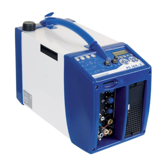
Polysoude PS 164-2 Manuals
Manuals and User Guides for Polysoude PS 164-2. We have
1
Polysoude PS 164-2 manual available for free PDF download: Operating, Maintenance And Programming Manual
Polysoude PS 164-2 Operating, Maintenance And Programming Manual (92 pages)
Brand:
Polysoude
| Category:
Portable Generator
| Size: 3 MB
Table of Contents
Table of Contents
3
Meaning of Symbols
5
Safety Precautions
5
Arc Welding Hazards
5
Recommendations
6
Devices for the Disconnection of Energy Sources
8
Failure Elimination
8
Extraction of Gas and Fumes
8
Prevention of Fi Re and Explosions
8
Protection in Case of Breakdown or Failure of the Equipment
8
Ergonomics
8
Maintenance and Adjustment Work
8
Training of the Operators
8
Safety Precautions Related to Power Sources
8
General Information
9
Introduction
10
The PS Power Sources
10
Fig. 3.1 - PS 164-2
10
Fig. 3.4 - MW Welding Head
11
Fig. 3.5 - UHP Welding Head
11
The Orbital Welding Heads
11
Fig. 3.3 - MU IV Welding Head
11
The Closed Chamber Welding Heads
11
The Open Welding Heads
11
The Tube to Tubesheet Welding Heads
12
Accessories
12
Fig.3.6 - TS Welding Head
12
Fig. 3.7 - Polyfi L Wire Feeder
12
Technical Specifi Cations of the Power Source PS 164-2
13
Design Features
13
The Remote Control Pendant
14
Fig. 3.9 - Remote Control Pendant
14
Technical Characteristics
15
Fig. 4.1 - Accessories of the PS 164-2 Power Source
16
Preparation of the PS 164-2
16
Installation
16
Installation
17
Input Power Connection
17
Fig. 4.2 - Name Plate of the PS 164-2 Power Source
17
Handling
17
Connection with Gas Supply
18
Fig. 4.4 - Diagram to Use Only One Gas
18
Fig. 4.5 - Diagram to Use Two Different Gas
18
Preparation for Work
19
Connection of the Remote Control Pendant
19
Connection of an MU Welding Head or a TP or TS Tube/Tube-Plate Welding Head
19
Fig. 4.7 - Connection of an MU Welding Head or a TP/TS Welding Head
19
Fig. 4.8 - Connection of an Air Cooled Closed Chamber Welding Head
20
Fig. 4.9 - Connection of a Liquid Cooled Closed Chamber Welding Head
20
Connection of a Liquid Cooled Closed Chamber Welding Head
20
Connection of an Air Cooled Closed Chamber Welding Head
20
Fig. 4.11 - Connection of a Manual Torch
21
Connection of a Wire Feed Unit
21
Fig. 4.10 - Connection of a Wire Feeder
21
Connection of a Manual Torch with Double Command
21
Controls
22
Front Panel
22
Back Panel
22
Fig. 4.13 - Back Panel
22
Fig. 4.12 - Front Panel
22
Synopsis
23
Fig. 4.14 - Synopsis
23
The Remote Control Pendant
24
Fig. 4.15 - the Remote Control Pendant
24
Adjustment of the Gas Fl Ow
25
Fig. 5.3 - Gas Test Button
25
Fig. 5.2 - Buttons for Wire Positioning on the Remote Control Pendant
25
Fig. 5.1 - Buttons for Manual Rotation of the Welding Head on the Remote Control Pendant
25
Wire Setting
25
Positioning the Welding Head on the Workpiece
25
Switching on
25
Fundamental Procedures
25
Operation of the PS 164-2
25
Manual Cooling System Start
26
Programmation Surface
26
Fig. 5.4 - Push Button "Cooling Circuit" - Start Pump "Cooling Circuit
26
Programming
27
Entering the Program Name
28
Modifying the Program Name
28
Choice of a Built-In Program
29
Programming and Modifying the Welding Parameters
30
Programming of Sectors
44
Deleting a Program from the Source Memory
47
Entering the Time and Date
48
Entering / Modifi Ying the Company Name
49
Saving, Loading a Program
49
Fig. 5.5 - Port for Memo Card
50
Printing a Program
51
Functioning Modes
51
Programmable Parameters
52
Weld Cycle
54
Fig. 5.8 - "Delta" Buttons for Modifi Cations of Parameter Values
54
Fig. 5.7 - "Start Cycle" Button
54
Fig. 5.6 - "Set up / Weld" Selector Switch
54
Simulation
54
Choosing the Program to be Executed
54
Safety Precautions
54
Execution of a Weld Program
54
End of Welding Cycle
55
Fig. 5.9 - Example of a Weld Cycle Report with Manual Downslope, Denoted by Error Code
55
Fig. 5.10 - Example of a Weld Cycle Report with a Normal Cycle End, Denoted by
55
Fig. 5.11 - Printer Switch
55
Fig. 5.14 - Emergency Stop Button
56
Fig. 5.13 - Immediate Manual Stop Button
56
Fig. 5.12 - Manual Downslope Button
56
Lternating Use of at Two Welding Stations on the same Workpiece
56
Manual Weld Cycle Stop
56
Servicing, Maintenance and Troubleshooting
57
Adjustments
57
Coolant
58
Printer
58
Loading Paper to the Printer
58
Change of Ribbon
58
Filter of the Cooling Circuit
59
Replacing Fuses
59
Trouble Shooting
60
Spare Parts
65
Fig. 6.12 - View Left Side
65
Fig. 6.13 - View Right Side
65
Fig. 6.14 - Topview
66
Fig. 6.15 - Rearview
66
Fig. 6.16 - Front View
67
Fig. 6.17 - Remote Control
67
Circuit Description
68
Fig. 6.18 - Wiring Diagram of PS 164-2 Power Sources with Serial Number from 08P89015 to
69
Fig. 6.19 - Wiring Diagram of PS 164-2 Power Sources with Serial Number from 08P89027
70
Fig. 6.20 - Sequencer Card
71
Fig. 6.21 - Synoptic Card
73
Fig. 6.22 - Remote Control Pendant Logic
74
Fig. 7.1 - Parameters Not Programmable
76
Fig. 7.2 - Weld Preparation
76
Built-In Programs
76
Appendix
76
Closed Chamber Welding Heads or MU Heads Without Fi Ller Wire
77
MU Open Welding Heads with Fi Ller Wire
78
TS/TP Welding Heads for Welding of Tubes to Tubesheet
79
Error Codes
80
Factory Settings of DIPS
81
Fig. 7.3 - Position of Switches on DIPS
81
End of Life, Recycling the Machine
83
Equipment Return Form
85
Table of Illustrations
87
Advertisement
Advertisement
Related Products
Polysoude PS 254
Polysoude P6
Polysoude P6 HW
Polysoude PS 406-2
Polysoude Categories
Portable Generator
Industrial Equipment
More Polysoude Manuals
Login
Sign In
OR
Sign in with Facebook
Sign in with Google
Upload manual
Upload from disk
Upload from URL