Sign In
Upload
Manuals
Brands
Polysoude Manuals
Portable Generator
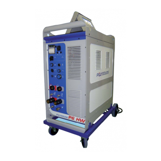
P6 HW
Polysoude P6 HW Manuals
Manuals and User Guides for Polysoude P6 HW. We have
1
Polysoude P6 HW manual available for free PDF download: Operating, Maintenance And Programming Manual
Polysoude P6 HW Operating, Maintenance And Programming Manual (100 pages)
Mobile power source
Brand:
Polysoude
| Category:
Portable Generator
| Size: 3 MB
Table of Contents
Table of Contents
3
1 Safety Instructions
5
Hazards Associated with Arc Welding
5
Meaning of the Symbols
5
Recommendations
6
Danger in Using a Power Source
8
Training of the Operators
8
Access for Maintenance and Adjustments
8
Ergonomics
8
Protection in the Event of Breakdown or Failure of the Equipment
8
Devices for Isolating Energy Sources
9
Prevention of Fi Re and Explosion
9
Preventing Release of Gas and Fumes
9
Faultfi Nding
9
2 General Information
10
Applicable Directives
10
Standards Applied
10
Reference Documents
10
3 Introduction
11
The P4-P6 Series
11
Fig. 3.3 - P6 HW Power Source
12
Fig. 3.1 - P4 Power Source
13
Fig. 3.2 - P6 Power Source
13
The Welding Heads
16
The Open Welding Heads
16
The Closed Chamber Welding Heads
16
Fig. 3.4 - MU IV Welding Head
16
Fig. 3.5 - Polycar Welding Carriage
16
Fig. 3.6 - MW Welding Head
16
The Tube to Tube Sheet Welding Heads
17
Accessories
17
Fig. 3.7 - TS 34 Welding Head
17
Fig. 3.8 - TS 2000 Welding Head
17
Fig. 3.9 - TS 8/75 Welding Head
17
Fig. 3.10 - Polyfi L-3 Wire Feeder
17
Technical Data for the P6 HW
18
Basic Design
18
Fig. 3.11 - Description of the P6 HW Power Source
19
The P6 HW Version Remote Control
20
Fig. 3.12 - Remote Control - Version P6 HW
20
Technical Characteristics
21
4 Setting to Work
22
Receiving a P6 HW Generator
22
Fig. 4.1 - P6 HW Power Source Accessories
22
Installation
23
Handling
23
Connection to Mains Electricity Supply
23
Fig. 4.2 - P6 HW Rating Plate
23
Connection with the Gas Supply
24
Fig. 4.3 - Connecting the Gas Supply to the P6 HW
25
Fig. 4.4 - Connection Diagram if One Gas Is Used
25
Fig. 4.5 - Connection Diagram if Two Different Gases Are Used
25
Connecting the Acquisition Module
26
Torch Cooler Connections
28
Fig. 4.6 - Connection of External Coolant to the P6 HW
28
Pc/Power Source Connection
29
Setting to Work
31
Remote Control Unit Connection
31
Fig. 4.8 - Connection of the Remote Control Unit to the P6 HW Power Source
31
Connection of an Open Welding Head of the MU Type or a Tube/Tube Sheet Welding Head of the Type TS or TP
32
Fig. 4.9 - Connection of an Open Welding Head of the MU Type or a Tube/Tube Sheet Welding
33
Connecting a "Polycar Hot Wire" Type Head
34
Fig. 4.10 - Connection of a "Polycar Hot Wire" Type Head
35
Connection of a Gas Cooled Closed Chamber Welding Head
36
Fig. 4.11 - Connection of a Gas Cooled Closed Chamber Welding Head
36
Connection of a Liquid Cooled Closed Chamber Welding Head with Integrated Command Buttons (MW 40-3, 65-3, 115-3, 170)
37
Fig. 4.12 - Connection of a Liquid Cooled Closed Chamber Welding Head with Integrated Com
37
Connection of a Wire Feed Unit
38
Fig. 4.13 - Connection of a Wire Feed Unit
38
Connection of a Closed Chamber Welding Head Equipped with Tacheo-Metry (Option)
39
Fig. 4.14 - Connection of a Closed Chamber Welding Head Equipped with Tacheometry
39
Connection of a Manual Torch with Double Command
40
Fig. 4.15 - Connection of a Manual Torch
40
Detection of the Welding Head
41
Detection of the "Open Head" Position
41
Oxygen Meter Option
42
Fig. 4.16 - Rear Panel of the Power Source and Oxygen Meter
42
Option Commands Mechanised Equipment
43
Fig. 4.17 - Power Source Rear Connection Panel
43
Fig. 4.18 - Modules
43
Fig. 4.19 - Ethernet Switch and Power Supply
43
Fig. 4.20 - Remote Control Unit with Emergency Stop
44
Fig. 4.21 - Connector Wiring
45
Description of Controls
46
Front Control and Connection Panel
46
Fig. 4.22 - Front Connector Panel
47
Rear Connector Panel
48
Fig. 4.23 - Rear Connector Panel
49
Remote Control Unit
50
Fig. 4.24 - Remote Control - Version P6 HW
51
Using the Remote Control to Regulate the AVC
52
5 Using the P6 HW Power Source
56
Fundamental Procedures
56
Switching on
56
Equipment Recognition
56
Positioning a Welding Head on the Workpiece
56
Wire Setting
56
Fig. 5.1 - Controls Used for Positioning the Electrode
56
Fig. 5.2 - Controls Used for Positioning the Fi Ller Wire
56
Adjustment of the Oscillation
57
Adjustment of the Gas Fl Ow
57
Switching on the Coolant Pump
57
Fig. 5.3 - Controls Used for Adjusting the Oscillation
57
Fig. 5.4 - Push Button for Testing Gas - Testing Coolant - and Restarting the Coolant Pump
57
Use
58
Safety Instructions
58
Program Selection
58
Simulation
58
Weld Cycle
58
Fig. 5.5 - Controls Used for Selecting the Wp/Program
58
Fig. 5.6 - "Simulation / with Arc" Indicator Lights
58
Fig. 5.7 - Pushbutton to Control Cycle Start
58
Fig. 5.8 - Pushbutton for Tuning During the Cycle
58
Stop at End of the Weld Cycle
59
Fig. 5.9 - "Override" Buttons for Developing Programs
59
Fig. 5.10 - Reprint Ticket for Weld Carried out
59
Induced Stoppage
60
Use of the USB Key
60
Start Cycle with Restart
60
Fig. 5.11 - Pushbutton to Command Stoppage with Slope down
60
Fig. 5.12 - Pushbutton to Command Immediate Stoppage
60
Fig. 5.13 - Polysoude USB Key
60
Fig. 5.14 - Push Button Start Cycle with Restart
60
6 Servicing, Maintenance and Troubleshooting
61
Servicing
61
Adjustments
61
Adjustment of the Tachometer
61
Fig. 6.1 - Position of Settings for the Source Interface Card 0028029400
62
Fig. 6.2 - Position of Settings for the Source Interface Card 0028029200
64
Fig. 6.3 - Position of Settings for the Arc Voltage Measurement Card 0028079100
65
Fig. 6.4 - Measuring Card 0028059100
67
Cooling Circuit
69
Printer
69
Fig. 6.4 - Printers
69
Maintenance and Troubleshooting
70
Replacement of Fuses
70
Cooling Circuit Fi Lter
70
Fig. 6.5 - Location of Fuses FU1, FU2 and FU3
70
Fig. 6.6 - Location of Fuse FU4
70
Fig. 6.7 - Coolant Fi Lter
70
Troubleshooting Guide
71
Transfert of Log-Fi Les
75
Fig. 6.8 - Connector for USB Key
75
Fig. 6.9 - Internal Right-Hand View
76
Fig. 6.10 - Internal Left-Hand View
76
Fig. 6.11 - Internal View from above
76
Spare Parts of the Power Source
77
Fig. 6.12 - View of P6 HW Remote Control Front Panel
78
Fig. 6.13 - Internal View of P6 HW Remote Control
78
Spare Parts for P6 HW Remote Control
79
Spare Parts of the Touchscreen
81
Electrical and Electronic Drawings
82
Fig. 6.15 - Block Diagram of the P6 HW Power Source for Gas, Current, Rotation and Wire-Fee
83
Fig. 6.16 - Block Diagram of the P6 HW for AVC, Oscillation and "Hot Wire
84
7 Appendix
85
Pre-Established Wps
85
Fig. 7.1 - Non-Programmable Settings
85
Fig. 7.2 - Preparing Tubes
85
Error and Codes Processing
86
List of Programmed Welding Parameters
87
8 End of Service Life, Recycling the Machine
91
9 Returned Equipment Form
93
Table of Illustrations
95
Advertisement
Advertisement
Related Products
Polysoude PS 254
Polysoude P6
Polysoude PS 164-2
Polysoude PS 406-2
Polysoude Categories
Portable Generator
Industrial Equipment
More Polysoude Manuals
Login
Sign In
OR
Sign in with Facebook
Sign in with Google
Upload manual
Upload from disk
Upload from URL