
Related Manuals for Polysoude PS 164-2


Summary of Contents for Polysoude PS 164-2
- Page 1 PS 164-2 Power source T I G - W i t h o r w i t h o u t W i r e Operating, maintenance and programming manual PN-0908073...
- Page 2 PS 164-2 Review of document Rev. 0 Original document. Rev. 1 Update following to review process. Rev. 2 Addition of new graphic style guide FNCA 1009-012 + FNCA 1012-015 (PLE - 12/2010) Rev. 3 Addition of information about coolant levels on page 64 (PLE - 07/2011) Rev.
-
Page 3: Table Of Contents
Design features ..................13 3. 3. 2. The remote control pendant ...............14 3. 4. Technical characteristics ..................15 Installation ......................16 4. 1. Preparation of the PS 164-2 ..................16 4. 2. Installation ......................17 4. 2. 1. Handling ....................17 4. 2. 2. Installation ....................17 4. - Page 4 PS 164-2 Operation of the PS 164-2 ..................25 5. 1. Fundamental procedures ..................25 5. 1. 1. Switching on ....................25 5. 1. 2. Positioning the welding head on the workpiece ..........25 5. 1. 3. Wire setting .....................25 5. 1. 4.
-
Page 5: Safety Precautions
PS 164-2 1. Safety precautions Note: Protect yourself and others from injury - read and follow these instructions 1. 1. Arc welding hazards The following symbols are used in the text to draw your attention and to identify risks and dangers. -
Page 6: Recommendations
PS 164-2 1. 3. Recommendations Risk of fume or gas inhala- tion Risk of electric shocks During welding, fumes and gases are released which are dangerous to your health. Avoid inhaling fumes. Live parts include the electrode, the weld circuit, the Origin of released fumes and gases: basic material, supply circuit and the internal circuits, the fi... - Page 7 PS 164-2 Warning: hot parts – Risk Risk of explosion of burn These risks are caused by using and handling gas • Do not touch welded or torch cut pieces. When bottles and fl ying sparks. handling hot workpieces, use adequate tools and/ or wear thick and isolating welding gloves, avoid- •...
-
Page 8: Safety Precautions Related To Power Sources
(electric, hydraulic, pneumatic, ...) is imposed by law. In case of mobile equipment or when Polysoude supplies only a part of the entire machine, the cus- At one side of the power source, a sticker indicates tomer is responsible to install the necessary missing that it is necessary to read the operating manual. -
Page 9: General Information
PS 164-2 Never use volatile solvents or fl ammable substances next to welding machinery. The electric arc could ac- cidentally ignite the vapours or combustible liquids. During repair and maintenance work on electric or electronic equipment, take off any jewellery (rings, watches, bracelets, etc.). -
Page 10: Introduction
PS 164-2 3. Introduction 3. 1. The PS power sources The power source PS 164-2 belongs to a versatile new family of universal and easy to use orbital TIG power sources. Special features are: • Welding sequences entirely programmable in the language of the welder. -
Page 11: The Orbital Welding Heads
PS 164-2 3. 2. The orbital welding heads The PS power sources support most of the Polysoude orbital welding heads. 3. 2. 1. The open welding heads • MU IV type (Fig.3.3) for standard or special ap- plications. Modular design. Weldhead designs to weld pipes, butt joint type, with or without fi... -
Page 12: The Tube To Tubesheet Welding Heads
PS 164-2 3. 2. 3. The tube to tubesheet welding heads TS welding heads with different features to meet all productivity and quality requirements. The standard weldhead for tube to tubesheet appli- cations. Open weldhead for slightly protruding or fl ush tubes. -
Page 13: Technical Specifi Cations Of The Power Source Ps 164-2
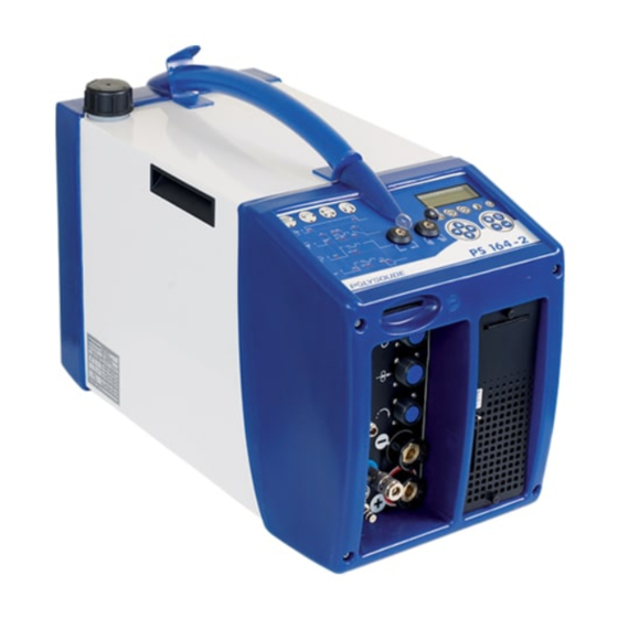
All connections are plugged on the connection panel welding cycle, the card reader and the printer. co in front of the power source. Fig. 3.8 - Description of power source PS 164-2 Screen Memo card drive Synoptic... -
Page 14: The Remote Control Pendant
PS 164-2 3. 3. 2. The remote control pendant This allows: • The positioning of welding heads and wire feed units • The starting and stopping of weld cycles • The selection of the program to be executed • The simulation of a cycle without welding •... -
Page 15: Technical Characteristics
PS 164-2 3. 4. Technical characteristics Single phase + earth Mains power input 220/230 V ± 10 % 50 or 60 Hz Current rating 16 A Open circuit voltage 60 V Insulating class Enclosure class IP 23 Range 160 A: 4 to 160 A... -
Page 16: Installation
• The remote control pendant BP 1436 (Pos. 1). • Two sets of keys (Pos. 7) • A ground cable 9 m in length (Pos. 2). Fig. 4.1 - Accessories of the PS 164-2 power source 16-92 PN-0908073 Rev. 11... -
Page 17: Installation
In case of using a truck, watch stability. 4. 2. 2. Installation For safe work the PS 164-2 has to be placed horizon- tally, on a fi rm surface. In this case a shaft system ensures the stability of the machines. -
Page 18: Connection With Gas Supply
PS 164-2 4. 2. 4. Connection with gas supply Gas kit for UHP Connection with the gas supply is made at the rear- This option integrated in the power source enables side of the power source (Fig.4.3) with the appropri- to keep a continuous gas fl... -
Page 19: Preparation For Work
Connection of the remote control pendant is made Connect the current cable on the "-" terminal with with the plug on the right side of the PS 164-2 on the quick connector, locking it by a short rotation to the screw connector.Make sure the securing ring is the right. -
Page 20: Connection Of An Air Cooled Closed Chamber Welding Head
Connect the manual commands cable on the FA 5 ing coupling disconnect fi tting situated at the bottom terminal (Fig. 2.12) on the connection plate. left hand corner of the front panel of the PS 164-2 ◊ Connection of the coolant circuit (symbol Connection is made by 2 quick push type self sealing ◊... -
Page 21: Connection Of A Wire Feed Unit
4. 3. 6. Connection of a manual torch with double command The wire feed unit is connected at the connection ◊ Connection of the electrode current cable panel of the PS 164-2 (symbol Connect the current cable on the " " terminal with... -
Page 22: Controls
PS 164-2 4. 4. Controls 4. 4. 2. Back panel 4. 4. 1. Front panel FA 1 On/off switch. FA 2 Connection for the remote control pen- FA 6 Connection of a second gas inlet [bac- dant cable. king gas] (option). -
Page 23: Synopsis
PS 164-2 4. 4. 3. Synopsis SY 1 Indicator "Printer mode". SY 16 Key to choose basic programs from the machine memory. SY 2 Indicator "Print report when weld cycle is fi nished". SY 17 Key for moving inside the synoptic. -
Page 24: The Remote Control Pendant
PS 164-2 4. 4. 4. The remote control pendant BT 1 Selection switch - "Set up / weld". BT 2 Emergency stop button. BT 3 Indicator Illuminated: Cycle in process. BT 2 BT 1 Flashing: Fault detected. BT 3 BT 4... -
Page 25: Operation Of The Ps 164-2
Note: The remote control must be connected tracts (BT 14) the wire. This action is comprised of to the PS 164-2 in order to make the power 2 speeds: during the fi rst 2 seconds the wire moves source work. -
Page 26: Manual Cooling System Start
For a program The time and date can be entered into the memory to be created, the proposed parameters are for ex- of the PS 164-2. Both the time and the date then ap- ample: pear on any printed weld cycle report. -
Page 27: Programming
PS 164-2 5. 3. Programming Explanation of symbols used The titles of the following chapters are: SYMBOL MEANING 3.3.1 Entering the program name. 3.3.2 Modifying the program name. Press once to increase 3.3.3 Choice of a built-in program. 3.3.4 Programming and modifying the welding... -
Page 28: Entering The Program Name
PS 164-2 5. 3. 1. Entering the program name 5. 3. 2. Modifying the program name To choose the number of the program, the switch of the remote control pendant has to be used. The current range (50A/160A) is set with the key operated switch on the front panel of the power source. -
Page 29: Choice Of A Built-In Program
PS 164-2 5. 3. 3. Choice of a built-in program The choice of a basic program is only possible after a After a basic program is chosen, the reference program name is entered. number of a welding head must be entered to allow the machine to calculate the travel speed. -
Page 30: Programming And Modifying The Welding Parameters
PS 164-2 5. 3. 4. Programming and modifying the welding 5. 3. 4. 1. Confi guration parameters Symbols appearing on the front panel: N A N T E S No ticket at the end of the welding cycle Printout of a ticket at the end of the... - Page 31 PS 164-2 5. 3. 4. 2. T10 = pregas time A short press of the key (less than one second) in- creases the value of a parameter by one increment. PN-0908073 Rev. 11 31-92 THE ART OF WELDING...
- Page 32 PS 164-2 A maintened press of the key increases the value of T11 = postgas time a parameter by one increment, then after one sec- ond the value continues to rise automatically until the key is released. The value rises by one incre-...
- Page 33 PS 164-2 5. 3. 4. 3. Current ◊ Prefusion I21 = prefusion current T21 = time of prefusion current. A maintained press of the key increases the value of Prefusion current will be non pulsed if selected choice a parameter by one increment, then after one sec- is within confi...
- Page 34 PS 164-2 ◊ Current I22 = high current T22 = time of high current I23 = low current T23 = time of low current 0 1 - N A N T E S I 2 2 = 0 9 0...
- Page 35 PS 164-2 ◊ Downslope N20 = start of downslope T25 = time of downslope 0 1 - N A N T E S N 2 0 = 0 3 6 5 0 1 - N A N T E S...
- Page 36 PS 164-2 5. 3. 4. 4. Rotation 0 1 - N A N T E S ◊ Calculation of the value to program to get a required linear travel speed R 3 0 = A 0 0 1 The table give a reference number R30 for the iden- tifi...
- Page 37 PS 164-2 V32 = Smooth welding speed or during T22 if pulsed rotation V33 = Welding speed during background current period if pulsed rotation 0 1 - N A N T E S V 3 2 = 0 7 0 %...
- Page 38 PS 164-2 ◊ Characteristics of the welding heads Open welding heads MU III and MU IV Minimum Maximum Reference Number of Welding head Factor C diameter diameter number impulses per type (VP=C.VL/D) (mm) (mm) (R30) revolution MU III 16 A014...
- Page 39 PS 164-2 Closed chamber welding heads with impulse power source Minimum Maximum Reference Number of Welding head Factor C diameter diameter number impulses per type (VP=C.VL/D) (mm) (mm) (R30) revolution H 500A 3.17 12.7 B007 HD 500 P 3.17 12.7...
- Page 40 PS 164-2 Welding heads TS-TP for tube to tubesheet welding Reference number R30 : Welding heads without switch to detect Axxx the home position. Welding heads with switch to return to Hxxx the home position after the end of the weld cycle, using the shortest way.
- Page 41 PS 164-2 Control of an external speed variator It is possible to control an external speed variator. There are two possibilities to program the reference number R30: For a time base of 1/10 seconds the letter I followed by 0,1 s has to be introduced (R30 = I0,1s).
- Page 42 PS 164-2 5. 3. 4. 5. Wire R40 = Selection of wire feeder 0 1 - N A N T E S A = Polyfi l B B = Polyfi l 2 and Polyfi l-3 T40 = Wire start R 4 0 = A...
- Page 43 PS 164-2 V43 = Wire speed during background current period if pulsed wire. N40 = Wire stop. T41 = Wire retract. 0 1 - N A N T E S V 4 3 = 0 5 0 0 1 - N A N T E S...
-
Page 44: Programming Of Sectors
PS 164-2 5. 3. 5. Programming of sectors 5. 3. 5. 1. Creation of a sector A sector is characterized by its number (S) and the The value of the parameter "N" for the actual sec- value (N) indicating the sector start position. - Page 45 PS 164-2 0 1 - N A N T E S N = 0 1 0 0 V 3 2 = 2 0 0 ‰ V 3 2 = 1 8 0 ‰ 0 1 - N A N T E S...
- Page 46 PS 164-2 5. 3. 5. 2. Modifi cation of sector start position During modifi cation, the value of parameter "N" must be between the values of the preceeding and the fol- lowing sector. If this is not the case, the value will 0 1 - N A N T E S not be accepted.
-
Page 47: Deleting A Program From The Source Memory
PS 164-2 5. 3. 5. 3. Deleting a sector C 1 - N A N T E S N = 0 1 3 0 I 2 2 = 1 0 0 I 2 2 = 1 0 5 I 2 2 = 1 2 0... -
Page 48: Entering The Time And Date
PS 164-2 5. 3. 7. Entering the time and date N A N T E S With the key switch in the open position, and when creating or modifying the name of a program, you can also access the mode for entering or modifying the time, the date and the company name by press- ing the "sector"... -
Page 49: Entering / Modifi Ying The Company Name
PS 164-2 5. 3. 8. Entering / modifi ying the company name 5. 3. 9. Saving, loading a program 5. 3. 9. 1. Saving a program on a memo card Each program can be saved on a memo card, 16 programs per card is possible. -
Page 50: Fig. 5.5 - Port For Memo Card
However, the number un- ◊ Loading of a single program der which it is stored in the PS 164-2 is not saved. • Insert the memo card. You can load the program under a new number or •... -
Page 51: Printing A Program
An error code will also appear on the display of the value and the correction made by each press of the PS 164-2. Appendix 7.2 gives the error codes, their delta button. meaning and their consequences. We advise you to When a delta button is used, the value of the param- take careful notice as to which error code is shown. -
Page 52: Programmable Parameters
PS 164-2 5. 3. 12. Programmable parameters For each parameter, the following table shows: • The synoptic reference (REF.). • The corresponding name. • The maximum value programmable. • The minimum value programmable. • The increment value that will be added or taken away when the buttons "... - Page 53 PS 164-2 DEFAULT DESIGNATION MAX. MIN. UNIT INCREMENT VALUE Pre-gas time Post-gas time Prefusion current 0,1* Prefusion time High current High current time 9999 Current Low current Low current time 9999 Downslope 9999 Downslope time Welding head reference See pages 38 to 41...
-
Page 54: Execution Of A Weld Program
If for the selected number a program does not ex- chapter 1 "Safety precautions". ist in the memory of the PS 164-2, no cycle will be started and the indicator will fl ash. The fl ashing can be turned off by pressing any button on the remote 5. -
Page 55: End Of Welding Cycle
PS 164-2 5. 4. 5. End of welding cycle 5. 4. 5. 1. Normal end of welding cycle In the case of a normal end of the welding cycle, the indicator on the remote control pendant extin- guishes. The power source is now ready to start a new cycle. -
Page 56: Manual Weld Cycle Stop
The remote control pendant is fi tted with an emer- gency button BT 2. By pressing this button, the PS 164-2 is immediately disconnected from the mains power supply. The weld, the movements and the gas fl ow are stopped suddenly. -
Page 57: Servicing, Maintenance And Troubleshooting
Polysoude recommends regular maintenance and calibration (once a year minimum) of the power source, either by a Polysoude techni- cian or by a technician approved by Polysoude. During the guarantee period the Polysoude contractual guarantee shall not apply if the... -
Page 58: Coolant
The refi lling of the coolant reservoir (about 2 l) is made by the top of the power source. NOTE : Only use coolant recommended by Polysoude. The use of any other coolant will void any warranty commitment. -
Page 59: Replacing Fuses
PS 164-2 6. 4. Replacing fuses A fuse blowing out indicates in 6. 5. Filter of the cooling circuit most cases a problem some- where in the electrical instal- A fi lter in built in the cooling circuit. We recommend lation. -
Page 60: Trouble Shooting
PS 164-2 6. 5. 1. Trouble shooting 6. 5. 1. 1. Noted defect when operating Observed defect Possible causes What to do The power source cannot • F2 or F3 fuse defect • Change (chap. 6.2.1) be turned on • Mains connection cable or plug defect •... - Page 61 PS 164-2 Observed defect Possible causes What to do No cycle start with a ma- • The plug of the torch is badly connected or • Check and correct nual torch laid • Replace • 21700633 defect Display vanishing • +5 V power card defect •...
- Page 62 PS 164-2 6. 5. 1. 2. Display of an error code Error code Possible causes What to do - Gas cylinder empty or gas valve is closed - Check - The quick coupling of the welding head is not correctly...
- Page 63 PS 164-2 Error code Possible causes What to do - Mains voltage too low - Correct or change the connection - Bad coupling to the mains - Change (§ 4.2.3) - Silicon hose defect (MU welding head) - Replace - Wrong position of S3/1 switch of 21700633 card - Place in "CLOSED"...
- Page 64 - Recorded program on the memory card is not suitable - Use a suitable program a memory card with PS 164-2 power source - Wrong position of S3/1 switch of 21700633 card - Place in "CLOSED" position - Wrong position of S3/4 switch of 21700633 card...
-
Page 65: Spare Parts
PS 164-2 6. 5. 2. Spare parts Designation Position Reference Relay 48 V 00544027 Relay 12 V (emergency stop) 9000544034 Rectifi er 00320042 Coolant fi lter 00699017 Water fi ltering element 00699016 Toric transformer 2040410145 Memory circuit interface 21700680 Gas safety valve... -
Page 66: Fig. 6.14 - Topview
PS 164-2 Designation Position Reference Gas solenoid valve 75301335 Single mains fi lter 16A/230V 00629098 Power supply card+5V 00629076 Synoptic card 21700634 Display 00503026 Key switch 00545112 Synoptic 2017005299 White cover 2017005240 Front cover blue 2017005280 Rear cover blue 2017005290 Fig. -
Page 67: Fig. 6.16 - Front View
PS 164-2 Designation Position Reference Ribbon for printer 00590064 Printer 00629078 Paper for printer 00590066 Fig. 6.16 - Front view Designation Position Reference Remote control pendant 14360000 Remote control pendant plug 00563085 Complete cable of the remote control pendant (with... -
Page 68: Circuit Description
The following information refers to the wiring The power switch consists of a self holding switch K2. scheme of the PS 164-2 (Ref. 1700XXXX) and the When the power is turned on, the K2 switch is acti- remote control pendant (Ref. 1436XXXX) as well as vated. -
Page 69: Fig. 6.18 - Wiring Diagram Of Ps 164-2 Power Sources With Serial Number From 08P89015 To
PS 164-2 Fig. 6.18 - Wiring diagram of PS 164-2 power sources with serial number from 08P89015 to 08P89026 PN-0908073 Rev. 11 69-92 THE ART OF WELDING... -
Page 70: Fig. 6.19 - Wiring Diagram Of Ps 164-2 Power Sources With Serial Number From 08P89027
PS 164-2 Fig. 6.19 - Wiring diagram of PS 164-2 power sources with serial number from 08P89027 70-92 PN-0908073 Rev. 11 THE ART OF WELDING... -
Page 71: Fig. 6.20 - Sequencer Card
PS 164-2 ◊ The sequencer card (21700633) The sequencer card includes several block func- tions: • Shielding gas control. • Central program unit (CPU) composed principally • Coolant control. of the microchip and the memory. • Interface with the manual torch •... - Page 72 The procedure for their ad- justment is given in paragraph 6.1.1. The memo cards used with the PS 164-2 are compat- ible with the databus I²C. The presence of a signal "Memo card engaged", resulting from a contact in the connector, authorises all other connections, including the 5 V power supply.
-
Page 73: Fig. 6.21 - Synoptic Card
PS 164-2 Fig. 6.21 - Synoptic card PN-0908073 Rev. 11 73-92 THE ART OF WELDING... -
Page 74: Fig. 6.22 - Remote Control Pendant Logic
PS 164-2 ◊ The source Emergency stop The power command, generated by the sequencer card, is an analogical signal 0 to 10 V. At 10 V, it cor- Stop responds to 160 A, and at 0 V it corresponds to the... - Page 75 PS 164-2 NOTES PN-0908073 Rev. 11 75-92 THE ART OF WELDING...
-
Page 76: Appendix
7. Appendix 7. 1. Built-in programs If fi ller wire is used, its diameter is always 0.8 mm. The Polysoude weld lab developed these programs The set-up of some parameters not programmable for mild steel and stainless steel tubes. Starting infl... -
Page 77: Closed Chamber Welding Heads Or Mu Heads Without Fi Ller Wire
PS 164-2 7. 1. 1. Closed chamber welding heads or MU heads without fi ller wire To use these programs for enclosed welding heads, a square-butt preparation is necessary. The programs which are valid for MU III welding heads are indicated by a star in the appropriate col- umn. -
Page 78: Mu Open Welding Heads With Fi Ller Wire
PS 164-2 7. 1. 2. MU open welding heads with fi ller wire Warning - For some welds the distance electrode-workpiece has to be modifi ed at the end of the cycle .These programs are marked with a star in the column named "Adjust at the end of cycle"... -
Page 79: Ts/Tp Welding Heads For Welding Of Tubes To Tubesheet
PS 164-2 7. 1. 3. TS/TP welding heads for welding of tubes to tubesheet Tube to tubesheet welds may have two geometrical In this case a welding bevel is needed on the workpiece shapes : fl ushing or protruding tubes. For welds of (angle = 45 °, height: 1.5 mm). -
Page 80: Error Codes
PS 164-2 7. 2. Error codes Number Origin Fault Consequence Lack of gas Immediate stop Coolant Coolant circuit n°1 failure Forced downslope Current Main voltage fault Cycle blocked Current No ignition Immediate stop Current Loss of arc Immediate stop Current... -
Page 81: Factory Settings Of Dips
PS 164-2 7. 3. Factory settings of DIPS Card Card Convention Closed Open Fig. 7.3 - Position of switches on DIPS PN-0908073 Rev. 11 81-92 THE ART OF WELDING... - Page 82 PS 164-2 82-92 PN-0908073 Rev. 11 THE ART OF WELDING...
-
Page 83: End Of Life, Recycling The Machine
PS 164-2 8. End of life, recycling the machine Our machines incorporate electrical and electronic components which must be recycled in accordance with EC Directive 2002/96/CE. Any item of equipment which is declared obsolete or out of service must be sent to ap- proved recycling companies in order to reduce the amount of ultimate waste disposal. - Page 84 PS 164-2 84-92 PN-0908073 Rev. 11 THE ART OF WELDING...
-
Page 85: Equipment Return Form
PS 164-2 RETU URN O F EQU UIPMEN Référenc ce du docum ment : PDS_ _FOR_032_R Retour maté ériel_EN Révision n : 04 Date d’a application : Nom du rédacteur : Please fill o out and join n this sheet w... - Page 86 PS 164-2 86-92 PN-0908073 Rev. 11 THE ART OF WELDING...
- Page 87 Fig. 4.1 - Accessories of the PS 164-2 power source .............. 16 Fig. 4.2 - Name plate of the PS 164-2 power source .............. 17 Fig. 4.3 - Gas connections at the right side of the PS 164-2 ............ 18 Fig. 4.4 - Diagram to use only one gas ................18 Fig.
- Page 88 PS 164-2 Fig. 5.3 - Gas test button ....................25 Fig. 5.4 - Push button "cooling circuit" - Start pump "cooling circuit" ........26 Fig. 5.5 - Port for memo card ..................... 50 Fig. 5.6 - "Set up / weld" selector switch ................54 Fig.
- Page 89 Fig. 6.18 - Wiring diagram of PS 164-2 power sources with serial number from 08P89015 to 08P89026 ........................ 75 Fig. 6.19 - Wiring diagram of PS 164-2 power sources with serial number from 08P89027 ..76 Fig. 6.20 - Sequencer card ....................77 Fig.
- Page 90 PS 164-2 90-92 PN-0908073 Rev. 11 THE ART OF WELDING...
- Page 91 PS 164-2 2009 Polysoude Original edition, Polysoude Nantes France SAS Photos, plans and drawings are used as help to the understanding and are thus not contractual. All rights reserved. No total or partial reproduction of this work can be made, under any format or by any means, electronic or mechanical, including photocopy, recording or computer techniques, without the writ- ten authorization of the publisher.
- Page 92 A welding application specialist in your area will advise you on the Maintenance and repair operations can be carried out at the welding process and appropriate equipment for your application. Polysoude plant as well as on site by our service network. Commissioning / Training Rental service A complete training program will enable you to start using the Increase the flexibility of your production! A large range of equipment...
Need help?
Do you have a question about the PS 164-2 and is the answer not in the manual?
Questions and answers