
Related Manuals for Polysoude P6 HW


Summary of Contents for Polysoude P6 HW
- Page 1 P6 HW Mobile power source T I G - H o t W i r e , A V C , O S C . Operating, maintenance and programming manual...
- Page 2 P6 HW Product P6 HW mobile power source Reference 0025069101 Manual PN-0110008 Redactor Document revision Rev. 0 Original 02/2011 Rev. 1 Update 09/2011 “Start cycle with restart” Rev. 2 Update "Option commands mechanised equipmen" 11/2011 Update: FNCA 1201-039 and FNCA 1201-019 – Items on pages 56, 57, 58 und 59 Rev.
-
Page 3: Table Of Contents
3. 2. 4. Accessories ...................... 17 3. 3. Technical data for the P6 HW ................... 18 3. 3. 1. Basic design ..................... 18 3. 3. 2. The P6 HW version remote control ............... 20 3. 4. Technical characteristics ....................21 Setting to work ......................22 4. - Page 4 6. 2. 4. Transfert of Log-fi les ..................75 6. 2. 5. Spare parts of the power source ................77 6. 2. 6. Spare parts for P6 HW remote control ..............79 6. 2. 7. Spare parts of the touchscreen ................81 6.
-
Page 5: Safety Instructions
P6 HW Safety instructions Warning: Protect yourself and others from injury − Read and follow these precautions. 1. 1. Hazards associated with arc welding The symbols reproduced below are used throughout this Technical Manual in order to draw your attention and identify the potential hazards. When you see one of these symbols, refer to the safety instruc- tions in the following section ‘Recommendations’. -
Page 6: Recommendations
P6 HW 1. 3. Recommendations Risk of inhaling fumes or Risk of electric shocks. gases. Welding generates fumes and gases which are The electrical components include the electrode, hazardous to health. Do not inhale the fumes. the welding circuit, the input circuit and the inter- Origin of the fumes and gases: Base metal, fi... - Page 7 P6 HW Warning: hot surfaces – Risk Risk of explosion. of burns. These risks are associated with the use and handling Do not touch welded or fl ame-cut components with of gas cylinders and fl ying sparks. bare hands. If such components have to be handled, use the appropriate tools and/or wear welders’...
-
Page 8: Danger In Using A Power Source
P6 HW 1. 4. Danger in using a power source Work or maintenance procedures described in this manual may be accompanied by dangers or risks. Such procedures are indicated by the following pictograms. Risk or situation with danger of serious injuries or even death. -
Page 9: Devices For Isolating Energy Sources
Isolation devices (electrical, hydraulic, pneumat- ment. ic, ...) are mandatory. If they do not form part of the POLYSOUDE supply (as is the case with porta- Before any maintenance work can be carried out ble installations), they MUST be provided by the user or an instrument is connected to a circuit, the the who must install them at his cost and responsibility. -
Page 10: General Information
P6 HW General Information 2. 1. Applicable directives 2004/108/EC Electromagnetic compatibility 2006/95/EC Electrical equipment designed to be used within certain voltage limits 2. 2. Standards applied EN 60974-1 Arc welding equipment - Part 1: Welding power sources EN 60974-10 Arc welding equipment — Part 10: Electromagnetic compatibility (EMC) require- ments. -
Page 11: Introduction
The P4-P6 series The P6 HW belongs to a new series of universal and functional power sources for orbital TIG welding. The complete realisation of a weld is the result of applying a WP (Weld Procedure), containing one or more programs... -
Page 12: Fig. 3.3 - P6 Hw Power Source
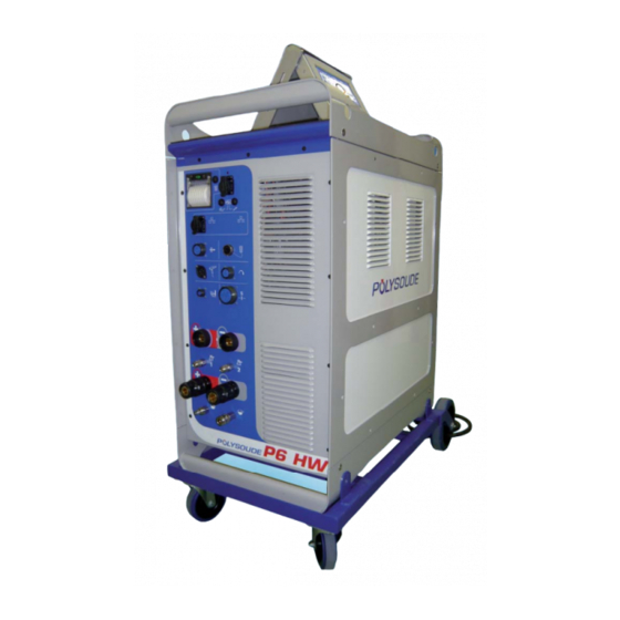
P6 HW P6 HW 520 A mobile power source. Ideal for high current, hot-wire welding. Fig. 3.3 - P6 HW power source 12-100 PN-0110008 Rev. 12 THE ART OF WELDING... -
Page 13: Fig. 3.1 - P4 Power Source
P6 HW 300 A mobile power source. Ideal for prefabrication work. 170 A mobile power source. Ideal for mobile use on site. Fig. 3.1 - P4 power source Fig. 3.2 - P6 power source PN-0110008 Rev. 12 13-100 THE ART OF WELDING... - Page 14 P6 HW P6 HW - 400/415 V ± 10%, 50/60 Hz (with standard couplings) with torch rotation control, touch screen, wire feeder control, printer, remote control pendant 6 axes, torch rotation control, arc voltage control (AVC), oscillation control (OSC) 00 2506 9105 14-100 PN-0110008 Rev.
- Page 15 P6 HW PN-0110008 Rev. 12 15-100 THE ART OF WELDING...
-
Page 16: The Welding Heads
P6 HW 3. 2. The welding heads These power sources support several of the Polys- oude series welding heads. 3. 2. 1. The open welding heads • MU IV type (Fig. 3.4) for standard or special applications. Modular design. Welding heads designed for butt welding pipes, with or without fi... -
Page 17: The Tube To Tube Sheet Welding Heads
P6 HW 3. 2. 3. The tube to tube sheet welding heads TS welding heads to meet sought-after produc- tivity and quality requirements. TS25, standard head for welding tubes/plates. Closed head, designed for fl ush or slightly protruding tubes. TS 34 standard head for welding tubes/ (Fig. -
Page 18: Technical Data For The P6 Hw
P6 HW 3. 3. Technical data for the P6 HW 3. 3. 1. Basic design The front panel also supports the printer and connec- The welding set contains the power source, all control tions for the USB key and the RJ45 link for connect- electronics and the torch cooling. -
Page 19: Fig. 3.11 - Description Of The P6 Hw Power Source
P6 HW Fig. 3.11 - Description of the P6 HW power source PN-0110008 Rev. 12 19-100 THE ART OF WELDING... -
Page 20: The P6 Hw Version Remote Control
Simulating weld programs. • Minor modifi cations during a weld cycle. • Shielding gas test. • Manual starting of the cooling pump(s) and the gas(es). Fig. 3.12 - Remote control - version P6 HW 20-100 PN-0110008 Rev. 12 THE ART OF WELDING... -
Page 21: Technical Characteristics
P6 HW 3. 4. Technical characteristics Three-phase + earth Mains power supply 400 V/415 V ± 10% 50 or 60 Hz Input current 25 A (400 V) No-load voltage Insulation class IP 23S (touchscreen closed) Protection rating IP 20 (touchscreen open) -
Page 22: Setting To Work
If a PC is used you must use the RJ45 cable supplied with the power source. Failure to use this cable may result in hazards for the user. Polysoude declines to accept any liability unless the PC/Power source connection is made with the RJ45 cable. -
Page 23: Installation
100% General 520A 420A U =78V The P6 HW power source is connected to the mains 30,8V 26,8V power supply with a cable containing 3 conductors + earth. A 3.5 m long cable is provided for this purpose. I1 max... -
Page 24: Connection With The Gas Supply
To ensure a successful welding cycle, please provide for a minimum of 2.5 L/min for Argon gas fl ow and 8 L/ min for Helium fl ow. Continuous gas option for UHP head on P6 HW A gas fl ow continuing outside the weld cycle can be obtained, if a UHP welding head is connected to a power source which is equipped with the continuous gas fl... -
Page 25: Fig. 4.3 - Connecting The Gas Supply To The P6 Hw
P6 HW Fig. 4.3 - Connecting the gas supply to the P6 HW Fig. 4.4 - Connection diagram if one gas is used Fig. 4.5 - Connection diagram if two different gases are used PN-0110008 Rev. 12 25-100 THE ART OF WELDING... -
Page 26: Connecting The Acquisition Module
P6 HW 4. 2. 5. Connecting the acquisition module Acquisition module Ethernet cable RJ45 240 V Power supply Printer (optional) Notebook P.C. 26-100 PN-0110008 Rev. 12 THE ART OF WELDING... - Page 27 P6 HW Measure connector of power source P6 HW welding power source PN-0110008 Rev. 12 27-100 THE ART OF WELDING...
-
Page 28: Torch Cooler Connections
P6 HW 4. 2. 6. Torch cooler connections The P6 HW must be connected to an external cooler. The connection to a wastewater system or external cooling system is at the rear of the power source. Fig. 4.6 - 1 "Water"... -
Page 29: Pc/Power Source Connection
If a PC is used you must use the RJ45 cable supplied with the pow- er source. Failure to use this cable may result in hazards for the user. Polysoude declines to accept any liability unless the PC/Power source connection is made with the RJ45 cable. - Page 30 P6 HW 4. 2. 8. Equipment compatibility To know the standard axis confi guration to equipments Polysoude, see the memo ‚‚Axis Confi guration Standard“. L’opérateur doit impérativement respecter le choix de types d’axes spécifi és par Polysoude. En cas de non respect de ce choix il existe de forts risques de destruction du matériel.
-
Page 31: Setting To Work
Remote control unit connection The wire feed unit is connected at the front connection panel of the P6 HW by a screw connector. If the remote control is not connected, a power source fi tted with the emergency stop option cannot be powered on. -
Page 32: Connection Of An Open Welding Head Of The Mu Type Or A Tube/Tube Sheet Welding Head Of The Type Ts Or Tp
P6 HW 4. 3. 3. Connection of an open welding head of the MU type or a tube/tube sheet welding head of the type TS or TP Connection of the electrode current cable Connect the current cable on the “-” terminal with the quick connector, locking it by rotation to the right. -
Page 33: Fig. 4.9 - Connection Of An Open Welding Head Of The Mu Type Or A Tube/Tube Sheet Welding
P6 HW Fig. 4.9 - Connection of an open welding head of the MU type or a tube/tube sheet welding head of the type TS or TP PN-0110008 Rev. 12 33-100 THE ART OF WELDING... -
Page 34: Connecting A "Polycar Hot Wire" Type Head
P6 HW 4. 3. 4. Connecting a “Polycar Hot Wire” type head Connecting the electrode and hot wire current cables Connect the current cable to the terminal marked “-” and the hot wire current cable to the “-” terminal circled in purple on the connection panel using quick connectors which lock by turning clockwise. -
Page 35: Fig. 4.10 - Connection Of A "Polycar Hot Wire" Type Head
P6 HW Fig. 4.10 - Connection of a “Polycar hot wire” type head PN-0110008 Rev. 12 35-100 THE ART OF WELDING... -
Page 36: Connection Of A Gas Cooled Closed Chamber Welding Head
4. 3. 5. Connection of a gas cooled closed chamber welding head Polysoude UHP heads belong to this group. Connection of the electrode current cable Connect the current cable on the “-” terminal with the quick connector, locking it by rotation to the right. This terminal is not marked by a colour. -
Page 37: Connection Of A Liquid Cooled Closed Chamber Welding Head With Integrated Command Buttons (Mw 40-3, 65-3, 115-3, 170)
Connection of the rotation motor cable The wire feed unit is connected at the front connection panel of the P6 HW by a screw connector (symbol ). Make sure that the securing ring is properly tightened, otherwise the system may not function correctly. -
Page 38: Connection Of A Wire Feed Unit
4. 3. 7. Connection of a wire feed unit The wire feed unit is connected at the front connection panel of the P6 HW by a screw connector (symbol Make sure that the securing ring is properly tightened, otherwise the system may not function correctly. -
Page 39: Connection Of A Closed Chamber Welding Head Equipped With Tacheo-Metry (Option)
P6 HW 4. 3. 8. Connection of a closed chamber welding head equipped with tacheo-metry (option) Adapters are mounted in the lines from the welding head to the power source/cooling system assembly: • Gas circuit • Torch rotation • Electrode current and water return •... -
Page 40: Connection Of A Manual Torch With Double Command
P6 HW 4. 3. 9. Connection of a manual torch with double command Connection of the electrode current cable Connect the current cable on the “-” terminal with the quick connector, locking it by rotation to the right. Earth cable connection Connect the earth cable to the “+”... -
Page 41: Detection Of The Welding Head
P6 HW 4. 3. 10. Detection of the welding head If the head connected to the power source does not correspond with the welding procedure selected, the cycle will not start. Select the correct procedure or change the head appropriately to enable the welding cycle to start. -
Page 42: Oxygen Meter Option
In order to use an oxygen meter with the power source it is essential to use the RS232 serial port cable sup- plied by Polysoude. Use of any other cable will result in major malfunction. Connect the RS232 serial port cable to connector FA 22 (Fig. 4.16 – 1) on the connection panel at the rear of the power source. -
Page 43: Option Commands Mechanised Equipment
P6 HW 4. 3. 13. Option commands mechanised equipment With this option the power source operates mecha- The auxiliary connector is connected to the outlet nised equipment type boom, positioner etc... The FA 20 (Fig. 4.17 - Pos.1) on the back cover of the power source is equipped with modules (Fig. -
Page 44: Fig. 4.20 - Remote Control Unit With Emergency Stop
P6 HW The rear connector 44–pin connector allows the drive. Here the representation of the connector with the I / O available. Fig. 4.20 - Remote control unit with emergency stop 44-100 PN-0110008 Rev. 12 THE ART OF WELDING... -
Page 45: Fig. 4.21 - Connector Wiring
P6 HW Item Designation Way A encoder 0V encoder Drive connects ready Order cycle stop 24 V max (input) Reverse gear 24 V max (input) 0V motor Not used (0->10V signal) Not used Not used Way B encoder 0V encoder... -
Page 46: Description Of Controls
P6 HW 4. 4. Description of controls 4. 4. 1. Front control and connection panel Item Description FA 2 Remote control unit connection. FA 3 Connection of the rotation system. FA 4 Connection of the wire feeder. FA 5 Connection of the command cable of a manual torch or of a type MW welding head. -
Page 47: Fig. 4.22 - Front Connector Panel
P6 HW FA 17 FA 16 FA 15 FA 19 FA 18 FA 14 FA 2 FA 4 FA 3 FA 5 FA 27 FA 26 FA 29 FA 28 FA 7 FA 9 FA 11 FA 10 FA 12 FA 13 Fig. -
Page 48: Rear Connector Panel
P6 HW 4. 4. 2. Rear connector panel Item Description Item Description FA 1 On/off switch. FA 23 Connection of a bar code reader. FA 6 Connection of the second gas supply (op- FA 24 Incoming external coolant feed (cold cir- tion). -
Page 49: Fig. 4.23 - Rear Connector Panel
P6 HW FA 20 FA 31 FA 21 FA 1 FA 22 FA 30 FA 32 FA 8 FA 32 FA 6 FA 24 FA 25 Fig. 4.23 - Rear connector panel PN-0110008 Rev. 12 49-100 THE ART OF WELDING... -
Page 50: Remote Control Unit
P6 HW 4. 4. 3. Remote control unit 4. 4. 3. 1. Functions of the components Item Function Item Function BT 6 Out cycle : Press the button BT 6 “I-” of the remote control pendant during several AF 1 4 line 20 character backlight display. -
Page 51: Fig. 4.24 - Remote Control - Version P6 Hw
BT 28 BT 27 BT 21 BT 26 BT 18 BT 22 BT 23 BT 25 BT 19 BT 24 V 10 BT 20 Fig. 4.24 - Remote control - version P6 HW PN-0110008 Rev. 12 51-100 THE ART OF WELDING... -
Page 52: Using The Remote Control To Regulate The Avc
P6 HW Item Function Item Function BT 13 Has two functions. BT 21 Pushbutton to toggle between the following Out of cycle: Controls coolant pump and gas 1 overrides: and 2 fl ow rates. In amplitude "A" ( V 7 illuminated). - Page 53 P6 HW BT 2 BT 1 BT 3 AF 1 BT 13 BT 4 BT 16 BT 15 BT 5 BT 14 BT 8 BT 6 BT 9 BT 7 BT 10 BT 12 BT 11 V 12 V 11...
- Page 54 P6 HW 4. 4. 4. 1. Layout of displays Examples of displayed messages out of weld cycle: Switching on End of installation > < > Example of fault message < > During a gas and water fl ow rate test. The message disappears when the button is <...
- Page 55 P6 HW Examples of displayed messages during a weld cycle: The display during a cycle shows: • on the fi rst two rows, the WP and the current program, • on the third row, the number of the current sector, elapsed time and the movement pulses, <...
-
Page 56: Using The P6 Hw Power Source
BT 12 (V 5 & V 6) allow the user to position the wire accurately. Depending on the date of manufacture, the P6 HW power source can detect the types welding heads or If the switch is in the “Auto” position, press- wire feeding units connected automatically. -
Page 57: Adjustment Of The Oscillation
P6 HW 5. 1. 5. Adjustment of the oscillation 5. 1. 7. Switching on the coolant pump Using buttons BT 24 and BT 25 on the remote After changing a welding head, and particularly if control, you can position the electrode in the axis of an extension cable is used, the coolant pipes may the joint. -
Page 58: Use
P6 HW 5. 2. 5. 2. 4. Weld cycle 5. 2. 1. Safety instructions Running a welding cycle • A weld cycle is started by pressing BT 15 on the Before starting any manipulation remote control unit. on the equipment please refer to chapter 1 “Safety precautions”. -
Page 59: Stop At End Of The Weld Cycle
P6 HW 5. 2. 5. Stop at end of the weld cycle Stop at end of a correct weld cycle If the end of a correctly executed weld cycle is reached, the message “Program end OK” is displayed on the remote control unit. The power source is then ready to start a new cycle. -
Page 60: Induced Stoppage
When the welding procedure is exported for the fi rst can be started at any moment during weld cycle time, a “Polysoude” folder is created in the root of execution by pressing BT 13 on the remote control the USB key. It is necessary to create it in the root of unit. -
Page 61: Servicing, Maintenance And Troubleshooting
P6 HW Servicing, maintenance and troubleshooting 6. 1. 2. Adjustment of the tachometer 6. 1. Servicing If the power source is equipped with the optional tachometer card, it is recommended to check whether 6. 1. 1. Adjustments the programmed speed corresponds to the real travel speed achieved by the rotation of the welding head. -
Page 62: Fig. 6.1 - Position Of Settings For The Source Interface Card 0028029400
P6 HW 62-100 PN-0110008 Rev. 12 THE ART OF WELDING... - Page 63 P6 HW PN-0110008 Rev. 12 63-100 THE ART OF WELDING...
-
Page 64: Fig. 6.2 - Position Of Settings For The Source Interface Card 0028029200
P6 HW 64-100 PN-0110008 Rev. 12 THE ART OF WELDING... -
Page 65: Fig. 6.3 - Position Of Settings For The Arc Voltage Measurement Card 0028079100
P6 HW PN-0110008 Rev. 12 65-100 THE ART OF WELDING... - Page 66 P6 HW 66-100 PN-0110008 Rev. 12 THE ART OF WELDING...
-
Page 67: Fig. 6.4 - Measuring Card 0028059100
P6 HW PN-0110008 Rev. 12 67-100 THE ART OF WELDING... - Page 68 P6 HW 68-100 PN-0110008 Rev. 12 THE ART OF WELDING...
-
Page 69: Cooling Circuit
P6 HW 6. 1. 3. Cooling circuit The cooling circuit is fi tted with a liquid temperature safety device which which stops the weld cycle stop and prevents cycle start-up from 80°C. 6. 1. 4. Printer Changing the printer paper. -
Page 70: Maintenance And Troubleshooting
6. 2. 2. Cooling circuit fi lter The P6 HW generator is fi tted with a fi lter in the cooling circuit. We recommend checking the cleanli- ness of the fi lter element every 6 months. -
Page 71: Troubleshooting Guide
(buttons "+" and "-" Change the selection. "modifi cations not allowed". inoperative) Touchscreen is illuminated but Contact Polysoude After Sales Serv- Touchscreen controller RS232 defect. inoperative ice. Connector J17 on the card LVDS Check. Nothing displayed on the touch- 0028069100 is unplugged. - Page 72 P6 HW Problem (Consequence) Possible causes What to do Gas bottle empty or valve closed. Check, replace or open. Quick coupling of the welding head Check. badly connected. (Immediate stop) Must be checked and, if necessary, Solenoid valve defect. replaced by a qualifi ed electrician.
- Page 73 P6 HW Problem (Consequence) Possible causes What to do Electrode in contact with the part to Correct. be welded. Electrode touches fi ller wire. Modify position of wire entry. Ignition device in contact with the Correct the position. torch (heads MU, TP, TS …).
- Page 74 0.3V off cycle between elec- (Immediate stop) higher than 0.3 V. If not, contact trode and part to be welded. Polysoude After Sales Service. 37 pin front connector (arc height/ Correct or modify connections or oscillation) not connected or cable replace cable if damaged.
-
Page 75: Transfert Of Log-Fi Les
To fi nd out the best solution in case of problems the so-called Log-fi les must be copied from the power source and sent to the Polysoude After Sales Service. Logs fi les should be recovered as soon as possible after the onset of the problem. -
Page 76: Fig. 6.9 - Internal Right-Hand View
P6 HW Fig. 6.9 - Internal right-hand view Fig. 6.10 - Internal left-hand view Fig. 6.11 - Internal view from above 76-100 PN-0110008 Rev. 12 THE ART OF WELDING... -
Page 77: Spare Parts Of The Power Source
P6 HW 6. 2. 5. Spare parts of the power source Fig 6.9 to Fig 6.11 Item. Order Code Description 00629085 Gas fl ow rate safety device 9000629198 Water fl ow rate safety device 0028219100 Adaptation of "hot wire" source... -
Page 78: Fig. 6.12 - View Of P6 Hw Remote Control Front Panel
P6 HW Fig. 6.12 - View of P6 HW remote con- trol front panel Fig. 6.13 - Internal view of P6 HW remote control 78-100 PN-0110008 Rev. 12 THE ART OF WELDING... -
Page 79: Spare Parts For P6 Hw Remote Control
P6 HW 6. 2. 6. Spare parts for P6 HW remote control Fig 6.12 and Fig 6.13 Item. Order Code Description 0026169102 Remote control complete (without emergency stop) 0026169103 Remote control complete (with emergency stop) 9000563323 Remote control plug 9000563326... - Page 80 P6 HW Fig. 6.14 -Internal view of the touchscreen 80-100 PN-0110008 Rev. 12 THE ART OF WELDING...
-
Page 81: Spare Parts Of The Touchscreen
P6 HW 6. 2. 7. Spare parts of the touchscreen Fig 6.14 Position Reference no. Designation 0026119199 Touchscreen unit 9000623722 Touchscreen 9000623724 Screen SVGA LVDS 10.4’ 9000623725 Backlight converter for the screen 9000623723 Touchscreen controller (old) 9000623790 Touchscreen controller (new 09/2013) -
Page 82: Electrical And Electronic Drawings
90 V to 260 V at 50 Hz or 60 Hz. The basic functions of the P6 HW are realised by a PC card of the PC104 standard, connected to the sequencer card (0028009100). This sequencer card is the main link between the commands issued by the PC card and the signals for the controlled devices. -
Page 83: Fig. 6.15 - Block Diagram Of The P6 Hw Power Source For Gas, Current, Rotation And Wire-Fee
P6 HW Fig. 6.15 - Block diagram of the P6 HW power source for gas, current, rotation and wire-feeding PN-0110008 Rev. 12 83-100 THE ART OF WELDING... -
Page 84: Fig. 6.16 - Block Diagram Of The P6 Hw For Avc, Oscillation And "Hot Wire
P6 HW Fig. 6.16 - Block diagram of the P6 HW for AVC, Oscillation and “hot wire” 84-100 PN-0110008 Rev. 12 THE ART OF WELDING... -
Page 85: Appendix
Fig. 7.1 Pos.2 Electrode diameter. the P6 HW power source can offer you the prede- Fig. 7.1 Pos.3 Sharpening angle of the elec- fi ned WP best suited to the request. You are then trode. -
Page 86: Error And Codes Processing
P6 HW 7. 2. Error and codes processing Cause Code Fault Consequence 4097 Gas fl owmeter not present (1) Stop 4465 Oxygen error (1) Stop 4673 Oxygen error (2) Stop 4529 Gas fl owmeter not present (2) Stop 4113 Cooling fl owmeter not present (1) -
Page 87: List Of Programmed Welding Parameters
P6 HW 7. 3. List of programmed welding parameters Gas axis Function Wording Ref. Min. Max. Unit Increment Default Prepurge time Pregas time 999,0 10,0 Postpurge time Postgas time 999,0 10,0 Oxygen Oxygen fl ow rate control 206400 50,0 threshold... - Page 88 P6 HW Rotation axis Function Wording Ref. Min. Max. Unit Increment Default Prerotation Prerotation time 60,0 time Pre-rolling Angle 9999 ° Tube diameter to be welded Diameter Rotation ramp time Ramp time 99,0 0 (b) then (c) 0 (b) Rotation speed (high)
- Page 89 P6 HW Arc voltage control axis – AVC (option) Function Wording Ref. Min. Max. Unit Increment Default Delay before start AVC leadtime 999,0 Ignition height Height 0,001 Torch height regulation Speed speed in/min 0,01 AVC sensitivity Sensitivity 20,0 Activate Stop AVC...
- Page 90 P6 HW 90-100 PN-0110008 Rev. 12 THE ART OF WELDING...
-
Page 91: End Of Service Life, Recycling The Machine
P6 HW End of service life, recycling the machine Our equipment incorporates electrical and electronic components which must be collected in accordance with Directive 2002/96/EC. Any item of equipment which is declared obsolete or out of service must be sent to approved recycling companies in order to reduce the amount of ultimate waste disposal. - Page 92 P6 HW 92-100 PN-0110008 Rev. 12 THE ART OF WELDING...
-
Page 93: Returned Equipment Form
P6 HW PN-0110008 Rev. 12 93-100 THE ART OF WELDING... - Page 94 P6 HW 94-100 PN-0110008 Rev. 12 THE ART OF WELDING...
- Page 95 Fig. 4.6 - Connection of external coolant to the P6 HW ............28 Fig. 4.8 - Connection of the remote control unit to the P6 HW power source ......31 Fig. 4.9 - Connection of an open welding head of the MU type or a tube/tube sheet welding head of the type TS or TP ................
- Page 96 Fig. 4.22 - Front connector panel ..................47 Fig. 4.23 - Rear connector panel ..................49 Fig. 4.24 - Remote control - version P6 HW ................51 Fig. 5.1 - Controls used for positioning the electrode ............. 56 Fig. 5.2 - Controls used for positioning the fi ller wire ............. 56 Fig.
- Page 97 Fig. 6.12 - View of P6 HW remote control front panel ............78 Fig. 6.13 - Internal view of P6 HW remote control ..............78 Fig. 6.15 - Block diagram of the P6 HW power source for gas, current, rotation and wire-fee- ding ......................83 Fig.
- Page 98 P6 HW 98-100 PN-0110008 Rev. 12 THE ART OF WELDING...
- Page 99 P6 HW 2010 Polysoude First Edition: Polysoude S.A.S. Nantes France. The photos, diagrams and drawings are used for greater ease of understanding and are therefore not contrac- tual. All rights reserved. No total or partial reproduction of this work will be made in any form or by any means whatsoever, be it electronic or mechanical, including photocopying, recording or by computer, without the written consent of the publisher.
Need help?
Do you have a question about the P6 HW and is the answer not in the manual?
Questions and answers