Sign In
Upload
Manuals
Brands
Panasonic Manuals
Camcorder
AJD810 - DVCPRO DIG CAMERA
Panasonic AJD810 - DVCPRO DIG CAMERA Manuals
Manuals and User Guides for Panasonic AJD810 - DVCPRO DIG CAMERA. We have
2
Panasonic AJD810 - DVCPRO DIG CAMERA manuals available for free PDF download: Operating Instructions Manual, Service Manual
Panasonic AJD810 - DVCPRO DIG CAMERA Operating Instructions Manual (273 pages)
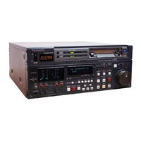
DVCPRO Digital Camera/VTR
Brand:
Panasonic
| Category:
Camcorder
| Size: 8 MB
Table of Contents
For Your Safety
2
Contents
3
General and Features
5
System Configuration
9
Power Supply Section
10
Accessory Mounting Section
11
Audio Function Section
12
Shooting/Playback Function Section
14
Menu Operation Section
20
Time Code-Related Section
20
Warning/Status Display Section
22
Power Supply
23
Using an Anton Bauer Battery Pack
23
Using a Sony Battery Pack
26
Using an AC Power Supply
28
Mounting the Lens
29
Adjusting the Lens Flange
30
Adjusting the White Shading
31
White Shading Adjustment Procedure
31
Adjusting the Viewfinder
33
Adjusting the Position
33
Adjusting the Diopter and Screen
34
Adjusting the Eyecup Position
34
Detaching the Eyecup
35
Remounting the Eyecup
35
Detaching the Viewfinder
36
Mounting the Viewfinder
36
Audio Input Preparations
37
Using the Microphone Mounted to the Main Unit
37
Using the Microphone Not Mounted to the Main Unit
39
Mounting a Wireless Microphone
41
Connecting an Audio Component
41
Mounting the Unit to a Tripod
42
Mounting the Shoulder Belt
43
Adjusting the Shoulder Pad Position
44
Attaching the Rain Cover
45
Connecting the AQ-EC1 Extension Control Unit
46
Displaying the Setting Menu Inside the Viewfinder
47
Setting Menu Configuration
47
Changing the Setting Menu Configuration
48
Basic Setting Menu Operations
49
Displaying the Setting Menu
49
Changing the Page
49
Selecting the Desired Item
50
Changing the Settings
50
Returning to the Default Settings
50
Quitting the Menu
50
Lamp Displays Inside the Viewfinder
51
Setting the ! Lamp Display
52
Selecting Display Items
56
Display Mode and Setting Change Message
57
Changing the Display Mode
58
Setting the Marker Displays
58
Setting the Camera ID
59
Remaining Battery Level and Audio Level Displays
60
VTR Section Operation/Status-Related Displays
60
Time Code-Related Displays
61
Adjustment and Setup Using the Setting Menu
62
Adjustments and Setup Using the Setting Menu
63
Setting the Gain Selector Value
64
Selecting Functions
65
Selecting the Required Functions
65
Adjusting the White Balance
66
Adjusting the Black Balance
69
Setting the Electronic Shutter
71
Shutter Modes
71
Setting the Shutter Mode/Speed
72
Setting the Synchro Scan Mode
73
Changing the Iris Automatic Adjustment Reference Value
74
Changing the Shutter Speed/Mode Selection Range
74
Adjusting the Audio Level
75
Manually Adjusting the Audio Level
75
Adjusting the Audio CH1 Lever from the Viewfinder
75
Limiter
75
When the Optimal Level Cannot be Set
76
Setting the Time Data
77
Setting the Time Code
77
Time Code Status During Battery Replacement
77
Setting the User Bit
78
User Bit Memory Function
78
Locking the Time Code to an External Source
79
Example of Connections for External Locking
79
External Lock Operation Procedure
80
Setting Time Data
80
Releasing the External Lock
80
Setup Card Operations
81
Setup Card Handling
81
Ejecting Setup Cards
81
Usage and Storage Precautions
81
Setup Card Data Operations
82
When Data Is Not Written
83
Data Format Error Messages
83
Writing Set Data to Cards
84
Protecting Stored Data
85
Reading out Data Stored on Cards
86
When Data Is Not Read out
86
Cassettes
87
Inserting and Ejecting Cassettes
87
Preventing Accidental Erasure
88
Ejecting Cassettes
88
Recording
89
Basic Procedures
89
Shooting Images
91
Successive Shooting
92
While Recording Is Paused
92
Successive Shooting in Other Cases
93
Playback - Checking Recorded Contents
94
Rec Review
94
Color Playback
94
Connection with an External VTR
95
Precautions When Connecting an External VTR
95
Checking the Function Settings
96
Starting Recording
96
Functions of the Unit's VTR SAVE/STBY Switch
97
Tape Running Mode
97
Viewing Playback Images on the Viewfinder
97
Using the 26-Pin/12-Pin Output Adaptor
98
Mounting the 26-Pin/12 Pin Output Adaptor
98
Controlling the External VTR with the Unit's Switches
99
Switching from the Internal VTR to the External VTR
99
RET Button
100
Lens RET Button Functions
100
Replacing the Backup Battery
101
Setting Menu Screens
102
Marker Screen
102
Menu Screen Display Methods
102
VF Display Screen
103
CAMERA ID Screen
104
Shutter Speed Screen
104
SYNCHRO SCAN Screen
105
LED Screen
105
SET up CARD Screen
106
Main Function Screen
107
BATT/TAPE ALARM Screen
107
Function 1/5 Screen
108
LOW Setting Screen
112
MID Setting Screen
113
HIGH Setting Screen
114
LEVEL Screen
115
VF Operation Screen
120
LENS ADJ Screen
121
Menu Select Screen
121
Auto Shading Screen
124
Data Reset Screen
124
Diagnostic Screen
124
Warning System
125
Emergency Eject
127
Error Codes
127
Maintenance
128
Condensation
128
Cleaning the Video Heads
128
Cleaning the Viewfinder
128
Inspections before Shooting
129
Inspection Preparations
129
Inspecting the Camera Section
129
Inspecting the Viewfinder
130
Inspecting the Iris and Zoom Functions
131
Inspecting the VTR Section
131
Tape Running Inspections
131
Specifications
133
Advertisement
Panasonic AJD810 - DVCPRO DIG CAMERA Service Manual (104 pages)
DVCPRO MECHANISM
Brand:
Panasonic
| Category:
Voice Recorder
| Size: 1 MB
Table of Contents
Table of Contents
2
Maintenance Parts Schedule Charts
4
Type of VTR (Except Camera Recorder)
4
Type of Camera Recorder
5
Parts and Sensor Location
6
Type of VTR (Except Camera Recorder)
6
Type of Camera Recorder
7
DVCPRO Test Fixture & Tool Kit List
8
Alignment Tapes
12
DVCPRO Alignment Tape
12
Vfm3380Km (Ntsc)
12
Vfm3580Km (Ntsc)
12
Vfm3581Km (Ntsc)
12
Vfm3582Km (Ntsc)
12
Vfm3583Km (Ntsc)
12
Vfm3480Km (Pal)
13
Vfm3680Km (Pal)
13
Vfm3681Km (Pal)
13
Vfm3682Km (Pal)
13
Vfm3683Km (Pal)
13
Cleaning Procedures
14
Cleaning of Head Chips : (Daily)
14
Cleaning of Drum Lead : (Weekly)
14
Cleaning of A/C Head : (Weekly)
14
Cleaning of Pinch Roller and Capstan : (Weekly)
14
Cleaning of Post : (Weekly)
14
Mechanical Adjustment
15
Name of Tape Transportation
17
Table of Test Point
19
Aj-Lt75, Aj-Lt85
19
Aj-D220, Aj-D230, Aj-D230H, Aj-D250
20
Aj-De77, Aj-D780
21
Aj-D200, Aj-D210, Aj-D215, Aj-D610, Aj-D700, Aj-D800, Aj-D810
22
Aj-D950, Aj-D950A
24
Aj-D90, Aj-D900, Aj-D910Wa, Aj-Pd900
25
Aj-D92, Aj-D94, Aj-D95Dc
26
Aj-D940
27
3 Mechanical Adjustment Procedure
28
Post Height Pre-Adjustment
28
Tension Adjustment Flowchart
28
Tension Arm Neutral Position Adjustment
29
Tension Arm Offset Adjustment
29
Tension Arm PLAY and REV Voltage Adjustment and Confirmation
31
Tension Regulator Spring Adjustment
31
REV Tension Confirmation
32
Tension Confirmation
33
Photo Sensor Voltage Adjustment
34
Tape Pass Adjustment Procedure
35
Envelope Waveform Adjustment
36
Post Limit Confirmation (PLAY)
37
A/C Head Adjustment Method (General)
38
A/C Head Height Adjustment
40
A/C Head Tilt Adjustment
40
A/C Head Tilt Confirmation
41
A/C Head Height Confirmation
42
A/C Head Azimuth and X-Value Adjustment (25M)
43
A/C Head Azimuth and X-Value Adjustment (50M)
44
A/C Head Azimuth and Horizontal Posiition Adjustment (AJ-D780 & AJ-DE77)
45
A/C Head Azimuth and Horizontal Position Adjustment (AJ-D940)
45
REV Tape Pass Confirmation and Adjustment (T4 Post Height Adjustment)
47
REV (-1) Mode Setting Procedure
49
Confirmation of Envelope on REV, REW and FF Mode
51
Play Tape Pass Limit Conformation
51
Confirmation of PLAY Start Envelope
52
FF, REW Mode Tape Pass Limit Confirmation
53
REV Mode Tape Pass Limit Confirmation
53
Screw Lock Tight of A/C Head and T3, T4 Post
53
Confirmation of Tape Damage for Long Tape Playback
54
LISTA Adjustment Procedure
55
Procedure (1) (25M Camera Recorder, Desk-Top)
55
Procedure (2) (25M Studio VTR, Lap-Top Editor)
56
Procedure (3) (50M Camera Recorder)
56
Procedure (4) (50M Studio VTR, Recorder)
57
Procedure (5) (4X Transmitter)
58
Procedure (6) (AJ-D940)
58
LISTA Connection and Boot up
59
How to Entry the Attachment Data of Alignment Tape
62
LISTA Sensitivity Adjustment and Sensitivity Detection
63
Sensitivity Adjustment Procedure (in Case of A, D, E, F, G, J Type Models)
64
Sensitivity Adjustment Procedure (in Case of B, H Type Models)
65
Sensitivity Adjustment Procedure (in Case of I Type Models)
66
Sensitivity Detection Procedure (Common to All Models)
67
LISTA Linearity Adjustment and Waving Measurement
68
Linearity Adjustment Procedures
69
Waving Measurement Procedures
70
Self-REC/PLAY Envelope Waveform Confirmation
71
4 No Tape Loading Procedures
72
In Case of Model Type A,B,C,D and E
72
In Case of Model Type F
72
5 Test Point and VR Location for CAMERA RECORDER
73
AJ-D400, AJ-D700 and AJ-D800 Series
73
AJ-D90, AJ-D610, AJ-D810, AJ-D900 and AJ-D910 Series
73
AJ-D200, AJ-D210 and AJ-D215 Series
74
Major Mechanical Parts Replacement & Adjustment Procedures
75
1 Major Mechanical Parts Replacement & Adjustment Procedures
76
General
76
Cylinder Unit Replacement
76
Cleaning Arm Unit Replacement
77
T1 Guide Position Adjustment
78
Adjustment Flow Chart after Cylinder Unit Replacement
79
Supply & Take-Up Reel Rotor Unit Replacement (Except Camera Recorder)
80
Supply & Take-Up Reel Rotor Unit Replacement (Camera Recorder Only)
81
Main Brake Torque Confirmation
82
Supply & Take-Up Brake Arm Unit Replacement (Except Camera Recorder)
82
Supply Brake Solenoid Replacement and Adjustment (Except Camera Recorder)
83
Take-Up Brake Solenoid Replacement and Adjustment (Except Camera Recorder)
84
Pinch Solenoid Replacement
85
Pinch Solenoid Position Adjustment
85
Pinch Arm Unit Replacement
86
Loading Motor Replacement
86
Mode SW Unit Replacement
87
Main Cam Gear Replacement
87
Thrust Screw Replacement and Adjustment
88
S5 Post Base Unit Replacement
88
Tension Arm Unit Replacement
89
T1 Boat Unit Replacement
91
M-Cassette Brake Base Unit Replacement (Camera Recorder Only)
93
Cleaner Solenoid Position Adjustment
96
Distinction SW Unit Replacement (Except Camera Recorder)
97
MIC Base Unit Replacement (Camera Recorder Only)
98
Reel Drive Motor Unit Replacement (Except Camera Recorder)
98
L-M Release Angle Unit Replacement (Except Camera Recorder)
98
T4 Post Position Adjustment
101
2 Connector Location
102
Mech. I/F P.C.board (Type a Model)
102
SERVO P.C.board (Type B Model)
102
SERVO P.C.board (Type C,D Model)
103
Advertisement
Related Products
Panasonic AJD810K - DVC
Panasonic AJD810P - DVC PRO
Panasonic DVCPRO AJ-D800E
Panasonic DVCPRO AJ-D800EN
Panasonic AJD200P - DVC PRO
Panasonic AJD215 - DVCPRO CAMCORDER
Panasonic AJD900W - DVC PRO 50 CAMCORDER
Panasonic AJ-D610WBp
Panasonic AJ-D400P
Panasonic AJ-D908MC
Panasonic Categories
Air Conditioner
Camcorder
TV
Digital Camera
Cordless Telephone
More Panasonic Manuals
Login
Sign In
OR
Sign in with Facebook
Sign in with Google
Upload manual
Upload from disk
Upload from URL