Sign In
Upload
Manuals
Brands
Optimum Manuals
Power Tool
OPTimill F 150
Optimum OPTimill F 150 Manuals
Manuals and User Guides for Optimum OPTimill F 150. We have
1
Optimum OPTimill F 150 manual available for free PDF download: Operating Manual
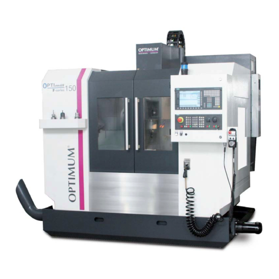
Optimum OPTimill F 150 Operating Manual (162 pages)
CNC-milling machine
Brand:
Optimum
| Category:
Power Tool
| Size: 8.65 MB
Table of Contents
Table of Contents
2
1 Safety
7
Glossary of Symbols
7
Safety Instructions (Warning Notes)
7
Classification of Hazards
7
Other Pictograms
8
Intended Use
9
Reasonably Foreseeable Misuses
9
Avoiding Misuses
10
Possible Dangers Caused by the CNC Machine
11
Qualification of Personnel
11
Target Group
11
Authorized Personnel
12
Operator Positions
13
Safety Devices
13
Lockable Main Switch
14
EMERGENCY STOP Push Button
15
Control Technical Protection
15
Polycarbonate Windows
15
Prohibition, Warning and Mandatory Labels
16
Safety Check
16
Personal Protective Equipment
17
Safety During Operation
17
Safety During Maintenance
18
Disconnecting and Securing the CNC Machine
18
Using Lifting Equipment
19
Mechanical Maintenance Work
19
Unattended Operation
19
Accident Report
19
Electrical System
20
Inspection Deadlines
20
Clamping Devices for Workpieces and Tools
20
Environmental Protection and Water Conservation
20
2 Technical Data
21
Electrical Connection
21
Lubricant/Coolant System
21
Compressed Air Supply
21
Dimensions
21
Working Area
22
Milling Table
22
Feed Drive Axis
22
Working Area, Traverse Path
23
Standard Tool Changer Carrousel
23
Optional Tool Changer Double Arm Gripper
23
Standard Milling Spindle Head
23
Milling Spindle Head with Use of a CTS System
24
Spindle Capacity
24
Environmental Conditions- Operation
25
Environmental Conditions - Storage
25
Optional Coolant Delivery through the Spindle
25
Dimensions Integrated Unit 20 Bar
25
Dimensions External Unit 20 Bar and 70 Bar
26
Emissions
27
Tools and Tool Holding Fixtures
27
3 Assembly and Commissioning
28
Dimensions of the Packing
28
Scope of Delivery
28
Transport
28
Storage
29
Installation Plan F150
30
Requirements Regarding the Installation Site
30
Transportation to the Installation Site
31
Forklift Truck
31
Crane
32
Installation and Assembly
33
Aligning the Machine
33
Assembly of the Coolant / Lubricant Tank and of the Chip Conveyor
34
Assembly of the Coolant / Lubricant Pumps
35
Mounting the Optional Coolant through Spindle
39
Mounting the Heat Exchanger on the Switch Cabinet
40
Mounting the Electronic Handwheel
40
Transport Locking Devices
41
Transport Locking Device, 16-Type Tool Changer
41
Transport Locking Device, Doors
41
Transport Locking Device, Axes
42
Mounting the Telescopic Covers
43
Corrosion Protection
43
Electrical Connection
43
Connection Compressed Air Supply
45
First Commissioning
46
Fill up Coolant
46
Refill Central Lubrication System
47
Functional Test and Controls
47
Warming up the Machine
48
Passwords
48
Data Backup on the Control
49
4 General Information about CNC
50
Compensation of Geometry
50
Coordinate Systems on CNC Machine Tools
50
Cartesian Coordinate System
50
Polar Coordinate System
51
Machine Coordinate System
51
Workpiece Coordinate System
51
Rotary Axes and Secondary Axes
52
NC Mathematics
52
Basics of the Coordinate Calculation
52
Parameters of a Triangle
52
Angle on a Triangle
52
Trigonometric Functions
53
5 User Interface, Machine Control Panel
54
Screen Arrangement
54
Key Definition of the CNC Full Keyboard
55
Keys and Key Combinations on the Control Panel
55
Controls on the Machine Control Panel
64
Key Switch
69
6 Operation
71
Safety
71
Control and Indicating Elements
71
Operating the Handwheel for Manual Travelling
72
Switching on the CNC Machine
73
Switching off the CNC Machine
74
First Insertion of a Tool
74
Insert Tool
74
Manual Operation of the Tool Changer
76
Manual Operation of the 16-Type Tool Changer
76
Manual Operation of the 24-Type Tool Changer
76
Quit the ATC-Service Mode
76
Setting
77
Clamping Workpiece and Setting Workpiece Datum
77
Setting Resp. Measuring Tool
78
Operational Modes
80
Programming
80
Start Program
80
Operating the Central Lubrication System
81
Data Interfaces and Current Collection
82
Executing from an External Position
83
7 Code List, M Functions
84
G Function According to PAL
85
8 Notes, Messages and Error Messages
86
9 Sinumerik 828 D
92
10 Maintenance
93
Operating Material
93
Machine Lubricants
93
Cooling Lubricants
93
Safety
94
Preparation
95
Restarting
95
Repair
95
Customer Service Technician
95
Inspection and Maintenance
96
Disassembly of the Cooling Lubricant Tank
100
Cleaning and Replacing of the Polycarbonate Windows
100
Cleaning Electrical Cabinet
101
Refill the Compressed Air Oiler
101
Drain Compressed Air Service Unit
102
Air Purge
102
Replacing of Compressed Air Filter
102
Refill Central Lubrication System
103
Fill up Coolant
103
10Cleaning of Oil Tank and Oil Filters on the Central Lubrication System
104
Optional CTS System
105
Cleaning and Replacing the Filters on the External CTS System
106
Cleaning and Replacing the Filters on the Internal CTS System
107
Cooling Lubricants and Tanks
108
Inspection Plan for Water-Mixed Cooling Lubricants
109
Network
110
Data Interfaces and Current Collection
110
Installation and Network Connection
110
Executing from an External Position
115
Adjusting the Amount of Oil at the Central Lubrication
116
11 Mechanische Ersatzteile - Mechanical Spare Parts
118
Ersatzteilbestellung - Ordering Spare Parts
118
Elektrische Ersatzteile - Electrical Spare Parts
118
Schaltplan - Wiring Diagram
118
Fräskopf - Milling Head
119
Säule - Column
121
Maschinenunterbau - Machine Stand
123
Frästisch - Milling Table 1- 2
125
Frästisch - Milling Table 2- 2
127
Baugruppe X-Achse - Assembly X- Axis
128
Baugruppe Y-Achse - Assembly Y- Axis
130
Baugruppe Z-Achse - Assembly Z- Axis
132
Maschinengehäuse - Machine Housing
134
Späneförderer - Chip Convejor
135
16-Fach Werkzeugwechsler - 16-Station Tool Changer
136
1Werkzeugwechsler 1-4 - Tool Changer 1-4
136
2Werkzeugwechsler 2-4 -Tool Changer 2-4
138
3Werkzeugwechsler 3-4 -Tool Changer 3-4
140
4Werkzeugwechsler 4-4 -Tool Changer 4-4
141
Optionaler 24-Fach Werkzeugwechsler - Optional 24-Station Tool Changer
143
1Werkzeugwechsler 1 von 5 - Tool Changer 1 of 5
143
2Werkzeugwechsler 2 von 5 - Tool Changer 2 of 5
144
3Werkzeugwechsler 3 von 5 - Tool Changer 3 of 5
145
4Werkzeugwechsler 4 von 5 - Tool Changer 4 of 5
146
5Werkzeugwechsler 5 von 5 - Tool Changer 5 of 5
147
Integriertes Kühlaggregat 20 Bar - Integrated Cooling Unit 20 Bar
149
Externes Kühlaggregat 20 Bar - External Cooling Unit 20 Bar
150
Externes Kühlaggregat 70 Bar - External Cooling Unit 70 Bar
151
EC - Declaration of Conformity
152
12 EC - Declaration of Conformity SIEMENS
153
13 Appendix 13.1 Copyright
154
13 Appendix
154
Changes
154
Product Follow-Up
154
Advice for Disposal / Options of Re-Use
155
Decommissioning
156
Disposal of the Packaging of New Devices
156
Disposal of the Machine
156
Disposal of Electrical and Electronic Components
156
Disposal of Lubricants and Coolants
157
Liability Claims for Defects / Warranty
155
Disposal Via Municipal Collection
157
Rohs, 2002/95/EC
157
Re-Export
158
Terminology/Glossary
159
Change Information Operating Manual
160
Advertisement
Advertisement
Related Products
Optimum Optimill F3
Optimum OPTIMILL MH 28V
Optimum OPTIMILL MF 2V
Optimum OPTImill MH 25V
Optimum Optimill MT 50E
Optimum OPTImill MH 50G
Optimum OPTImill MH 50V
Optimum OPTimill MH 35G
Optimum OPTimill MH 35V
Optimum OPTImill MZ 25
Optimum Categories
Kettle
Drill
Kitchen Appliances
Blender
Power Tool
More Optimum Manuals
Login
Sign In
OR
Sign in with Facebook
Sign in with Google
Upload manual
Upload from disk
Upload from URL