Sign In
Upload
Manuals
Brands
Nuvoton Manuals
Motherboard
NuMaker-HMI-N9H30
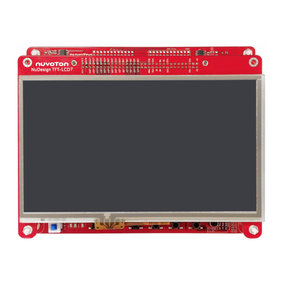
Nuvoton NuMaker-HMI-N9H30 Manuals
Manuals and User Guides for Nuvoton NuMaker-HMI-N9H30. We have
1
Nuvoton NuMaker-HMI-N9H30 manual available for free PDF download: User Manual
Nuvoton NuMaker-HMI-N9H30 User Manual (39 pages)
Evaluation Board for NuMicro N9H30 Series
Brand:
Nuvoton
| Category:
Motherboard
| Size: 3 MB
Table of Contents
Table of Contents
2
Overview
5
Figure 1-1 Front View of Numaker-HMI-N9H30 Evaluation Board
5
Figure 1-2 Rear View of Numaker-HMI-N9H30 Evaluation Board
6
Features
7
Numaker-N9H30 Main Board Features
7
Nudesign-TFT-LCD7 Extension Board Features
7
Supporting Resources
8
Numaker-Hmi-N9H30 Hardware Configuration
9
Numaker-N9H30 Board - Front View
9
Figure 2-1 Front View of Numaker-N9H30 Board
9
Table 2-1 LCD Panel Combination Connector (CON8) Pin Function
11
Table 2-2 Three Sets of Indication LED Functions
12
Table 2-3 Six Sets of User SW, Key Matrix Functions
12
Table 2-4 CMOS Sensor Connector (CON10) Function
13
Numaker-N9H30 Board - Rear View
14
Figure 2-2 Rear View of Numaker-N9H30 Board
14
Table 2-5 JTAG ICE Interface (J2) Function
14
Table 2-6 Expand Port (CON7) Function
16
Table 2-7 UART0 (J3) Function
16
Table 2-8 UART2 (J6) Function
16
Table 2-9 RS-485_6 (SW6~8) Function
17
Table 2-10 Power on Setting (SW4) Function
17
Table 2-11 Power on Setting (S2) Function
17
Table 2-12 Power on Setting (S3) Function
17
Table 2-13 Power on Setting (S4) Function
17
Table 2-14 Power on Setting (S5) Function
17
Table 2-15 Power on Setting (S7/S6) Function
18
Table 2-16 Power on Setting (S9/S8) Function
18
Table 2-17 CMOS Sensor Connector (CON9) Function
19
Table 2-18 CAN_0 (SW9~10) Function
19
Nudesign-TFT-LCD7 - Front View
20
Figure 2-3 Front View of Nudesign-TFT-LCD7 Board
20
Nudesign-TFT-LCD7 - Rear View
21
Figure 2-4 Rear View of Nudesign-TFT-LCD7 Board
21
Numaker-N9H30 and Nudesign-TFT-LCD7 PCB Placement
22
Figure 2-5 Front View of Numaker-N9H30 PCB Placement
22
Figure 2-6 Rear View of Numaker-N9H30 PCB Placement
22
Figure 2-7 Front View of Nudesign-TFT-LCD7 PCB Placement
23
Figure 2-8 Rear View of Nudesign-TFT-LCD7 PCB Placement
23
Numaker-N9H30 and Nudesign-Tft-Lcd7 Schematics
24
Numaker-N9H30 - GPIO List Circuit
24
Figure 3-1 GPIO List Circuit
24
Numaker-N9H30 - System Block Circuit
25
Figure 3-2 System Block Circuit
25
Numaker-N9H30 - Power Circuit
26
Figure 3-3 Power Circuit
26
Numaker-N9H30 - N9H30F61IEC Circuit
27
Figure 3-4 N9H30F61IEC Circuit
27
Numaker-N9H30 - Setting, ICE, RS-232_0, Key Circuit
28
Figure 3-5 Setting, ICE, RS-232_0, Key Circuit
28
Numaker-N9H30 - Memory Circuit
29
Figure 3-6 Memory Circuit
29
Numaker-N9H30 - I S, I2C_0, RS-485_6 Circuit
30
Figure 3-7 I 2 S, I2C_0, RS-486_6 Circuit
30
Numaker-N9H30 - RS-232_2 Circuit
31
Figure 3-8 RS-232_2 Circuit
31
Numaker-N9H30 - LCD Circuit
32
Figure 3-9 LCD Circuit
32
3.10 Numaker-N9H30 - CMOS Sensor, I2C_1, CAN_0 Circuit
33
Figure 3-10 CMOS Sensor, I2C_1, CAN_0 Circuit
33
3.11 Numaker-N9H30 - RMII_0_PF Circuit
34
Figure 3-11 RMII_0_PF Circuit
34
3.12 Numaker-N9H30 - RMII_1_PE Circuit
35
Figure 3-12 RMII_1_PE Circuit
35
3.13 Numaker-N9H30 - USB Circuit
36
Figure 3-13 USB Circuit
36
3.14 Nudesign-TFT-LCD7 - TFT-LCD7 Circuit
37
Figure 3-14 TFT-LCD7 Circuit
37
Revision History
38
Advertisement
Advertisement
Related Products
Nuvoton NuMicro NuMaker-HMI-N9H20
Nuvoton NuMaker-HMI-N9H26
Nuvoton NuMaker-HMI-M032K
Nuvoton NuMaker-HMI-M467
Nuvoton NuMicro NuMaker-HMI-MA35D1-S1
Nuvoton NuMaker-HMI-MA35H0-A1
Nuvoton NuMaker-HMI-MA35H0-A2
Nuvoton NuMaker-HMI-N9H31-A1
Nuvoton NuMaker-HMI-N9H31-A2
Nuvoton NuMaker NUC980
Nuvoton Categories
Motherboard
Microcontrollers
Computer Hardware
Amplifier
Computer Accessories
More Nuvoton Manuals
Login
Sign In
OR
Sign in with Facebook
Sign in with Google
Upload manual
Upload from disk
Upload from URL