Sign In
Upload
Manuals
Brands
Nortel Manuals
Network Hardware
R2MFC
User Manuals: Nortel R2MFC Installation
Manuals and User Guides for Nortel R2MFC Installation. We have
1
Nortel R2MFC Installation manual available for free PDF download: Installation And Configuration Manual
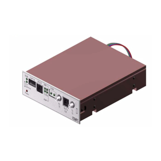
Nortel R2MFC Installation And Configuration Manual (114 pages)
Media Bay Module
Brand:
Nortel
| Category:
Network Hardware
| Size: 2 MB
Table of Contents
Configuration Guide
1
North American Regulatory Information
2
Safety
2
Enhanced 911 Configuration
3
Radio-Frequency Interference
3
Hearing Aid Compatibility
4
Repairs
4
Important Safety Instructions
4
Installation
4
International Regulatory Information
5
Table of Contents
7
Getting Help from a Specialist by Using an Express Routing Code
13
Getting Help from the Nortel Web Site
13
How to Get Help
13
Getting Help over the Phone from a Nortel Solutions Center
13
Getting Help through a Nortel Distributor or Reseller
13
Chapter 1 Getting Started
15
About this Guide
15
Audience
15
Before You Begin
16
Acronyms
16
Symbols and Text Conventions
17
Related Publications
19
Chapter 2 Overview
21
General Information
21
Administration and Maintenance Tools
22
R2MFC MBM Faceplate Elements
22
System Status Leds
23
Config DIP Switches
23
RS232 Port
24
E1 Status Leds
24
Bantam Jacks
24
BNC and RJ-48 Connectors
24
R2MFC MBM Back and Underside Elements
24
Power Connectors
25
MBM DIP Switches
25
Chapter 3 Preparing to Install the R2MFC MBM
27
Installation Process Map
28
Host System Setup Requirements
28
R2MFC MBM Setup Requirements
29
Config DIP Switches
29
MBM DIP Switches
29
Environment Checklist
30
Electrical Requirements
30
Software Requirements
30
Customer Supplied Hardware Requirements
30
Chapter 4 Installing the R2MFC MBM
31
Shutting down the System
32
Shutting down a BCM 4.0 System
32
Shutting down the BCM 4.0 System Software
32
Shutting down the BCM 4.0 System Hardware
33
Shutting down a BCM 3.7 or Lower System
33
Installing an R2MFC MBM
34
Installing an R2MFC MBM in the BCM Platform Base Chassis
34
Installing an R2MFC MBM in the Expansion Unit
35
Installing an R2MFC MBM in the BCM50 Expansion Unit
36
Installing the Rubber Boot in an R2MFC Module
36
Reconnecting the Equipment
38
Removing an R2MFC MBM
38
Removing an R2MFC MBM from the BCM Platform Base Chassis
39
Removing an R2MFC MBM from the Expansion Unit
40
Wiring an R2MFC MBM
41
Connecting an R2MFC MBM to a Service Provider
43
Chapter 5 Configuring the R2MFC MBM
45
MFCR2 Side (External Link) Configurable Parameters
46
Physical Line Characteristics
46
E1 Framing
46
Line Signaling
47
Register Signaling
47
End of Dialing (Incoming)
48
End of Dialing (Outgoing)
48
Disable ANI
48
Default Category
49
Default Subscriber Status
49
Configuring the MFCR2 (External) Link
49
Setting Config DIP Switches
49
Creating a Customized Country Code
50
Appendix A, "Configuring DIP Switch Settings and Definitions," on Page
50
PRI Side (Internal Link) Configurable Parameters
51
E1 Framing
51
Signaling
52
Configuring the PRI (Internal) Link
52
Configuring the PRI (Internal) Link Using Element Manager
52
Configuring the PRI (Internal) Link Using Unified Manager
54
Turning on Second Dial Tone
58
Turning on Second Dial Tone Using Element Manager
58
Turning on Second Dial Tone Using Unified Manager
59
Chapter 6 R2MFC MBM Maintenance
61
Inter-Working Functionality
61
Clock Synchronization
62
Diagnostic Tools
63
Setting the R2MFC MBM to Diagnostic Mode
63
Alarms
64
Alarms Measurements
64
Group I Errors
64
Group II Errors
65
Alarms Propagation
65
Faceplate Leds
66
Logs and Traces
67
Error Messages
67
Replacing an R2MFC MBM
68
Chapter 7
69
Upgrading Firmware
69
Parameter Setting
70
Command Line Interface (CLI)
73
Overview
73
Users and Passwords
73
Accessing the CLI
74
Load Directory
75
Info Directory
75
View Directory
76
Cntrl Directory
77
Config Directory
79
Alarm Directory
81
Swerr Directory
83
MFC Directory
84
R2 Directory
87
PRI Directory
89
Configuring DIP Switch Settings and Definitions
91
Country Code Defaults
93
Mexico Config 1
93
E1 Physical Characteristics
93
E1 Framing
93
Register Signaling
93
R2 Line Signaling
93
MFC Register Signaling
94
Mexico Config 2
95
E1 Physical Characteristics
95
E1 Framing
95
Register Signaling
95
R2 Line Signaling
96
MFC Register Signaling
96
Brazil Config 1
98
E1 Physical Characteristics
98
E1 Framing
98
Register Signaling
98
R2 Line Signaling
98
MFC Register Signaling
98
Brazil Config 2
100
E1 Physical Characteristics
100
E1 Framing
100
Register Signaling
100
R2 Line Signaling
101
MFC Register Signaling
101
Argentina Config 1
102
E1 Physical Characteristics
102
E1 Framing
103
Frame Mode: Alternate
103
Register Signaling
103
R2 Line Signaling
103
MFC Register Signaling
103
Chile Config 1
105
E1 Physical Characteristics
105
E1 Framing
105
Frame Mode: Alternate
105
Register Signaling
105
R2 Line Signaling
105
MFC Register Signaling
106
Panama Config 1
107
Appendix B Diagnostic and Loopback DIP Switch Settings
109
Appendix C
111
MFC Signal Definitions
111
Appendix D
113
CLI Cable Pinout
113
Advertisement
Advertisement
Related Products
Nortel RLC
Nortel R10.0
Nortel Regular Telephone
Nortel Annex Communications Server R10.0B
Nortel Annex Host Tools R14.2
Nortel Ethernet Routing Switch 8600
Nortel Ethernet Routing Switch 8000 Series
Nortel 1001t
Nortel 1010 Series
Nortel 1050 Series
Nortel Categories
IP Phone
Telephone
Switch
Software
Server
More Nortel Manuals
Login
Sign In
OR
Sign in with Facebook
Sign in with Google
Upload manual
Upload from disk
Upload from URL