Sign In
Upload
Manuals
Brands
NKT Photonics Manuals
Control Unit
Koheras BASIK
NKT Photonics Koheras BASIK Manuals
Manuals and User Guides for NKT Photonics Koheras BASIK. We have
2
NKT Photonics Koheras BASIK manuals available for free PDF download: Product Manual, Instruction Manual
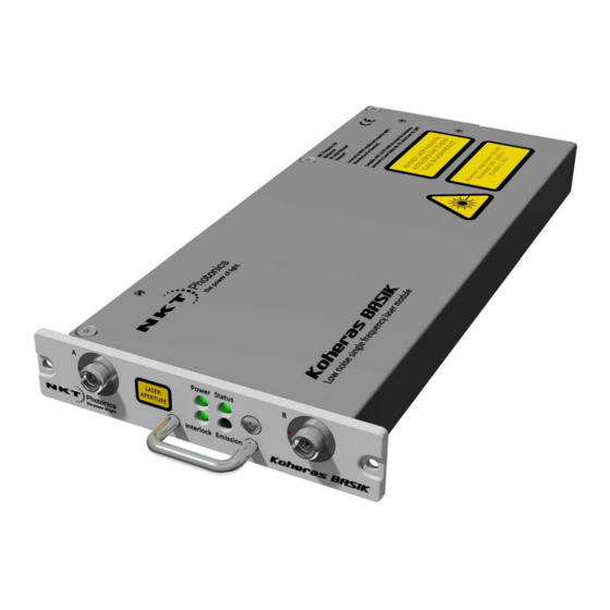
NKT Photonics Koheras BASIK Product Manual (126 pages)
Low Noise Single Frequency Laser Module
Brand:
NKT Photonics
| Category:
Measuring Instruments
| Size: 16.33 MB
Table of Contents
Guide Overview
3
Terminology
3
Table of Contents
7
Tables
13
Figures
15
Procedures
19
Koheras Basik Description
21
Laser Description
23
Features and Options
23
Figure 1 BASIK Front Panel
23
Theory of Operation
24
Module Variants
24
Configuration ID
24
Center Wavelength
24
Table 1 BASIK Variant Specifications
24
Output Power
25
Tuning Types
25
Front and Rear Panels
25
Front Panel
25
Rear Panel
26
Figure 2 BASIK Front Panel Layout
26
Optical Specifications
27
Laser Features
27
Thermal Tuning
27
Figure 3 BASIK Rear Panel Layout
27
Fast Wavelength Modulation
28
Figure 4 Frequency Response Using Wavelength Modulation
28
External Cavity Stabilization
29
Operating Mode
29
Trigger
29
Auto-Start
29
Table 2 Recommended Power Modes
29
Emission Delay
30
Shutdown Delay
30
High Temperature Shutdown
30
Power Verification
30
Miscellaneous
31
Power Supply
31
Safety
31
Accessories
31
Figure 5 USB-RS485 Adapter
31
Optical Interface
32
Optical Fibers, Connectors and Adapters
32
Figure 6 BASIK Equipped with Fiber Cord and FC/APC Connector
32
Laser Control
33
User Interface
33
Status Leds
33
Table 3 Optical Interface Specifications
33
Figure 7 Status Leds
33
Module Labels
34
Table 4 Status Leds
34
Figure 8 Top Panel Label Locations
34
Table 5 Module Labels
35
Figure 9 Front Panel Label Locations
35
Modulation
37
Fast Wavelength Modulation
37
Configuring External and Internal Wavelength Modulation
37
Wavelength+/- Signal
38
Table 6 Wavelength Modulation Settings
38
Differential Input
39
Single-Ended to Differential
39
Singled-Ended Input
39
Figure 10 Differential Input Signal for Wavelength Modulation
39
Figure 11 Single-Ended to Differential
39
Figure 12: Single-Ended Input Signal with 2.5 V
40
Figure 13 Single-Ended Input with 2.5 V on an Unused Branch
40
Wavelength- to GND
41
Figure 14 Single-Ended Input Signal with GND on an Unused Branch
41
Figure 15 Single-Ended Input Connections with 0 V on an Unused Branch
41
Differential Output
42
Wavelength Modulation Coupling
42
Narrow Versus Wide Modulation Range
42
Frequency Response
42
Table 7 Narrow Vs Wide Band Wavelength Modulation
42
Figure 16 Differential Output Signal
42
Figure 17 BASIK X15 Wavelength Modulation Response
43
External Cavity Stabilization (BASIK X15)
44
Figure 18 BASIK E15/C15/Y10 Wavelength Modulation Response
44
Figure 19 BASIK X15 in Pound-Drever-Hall Configuration
44
Setting up External Cavity Stabilization
45
Operating the Laser
47
Communicating with the Laser
49
Connection Kit
49
CONTROL Software
49
Installing the Software
49
Table 8 Koheras BASIK PC Connection Kit
49
Software Development Kit
50
Generic User Interface
50
Connecting CONTROL to the Laser
50
Procedure 1 Connecting CONTROL to the Laser
50
Procedure 2 Connecting the SDK Generic User Interface to the Laser
52
Connecting the SDK GUI to the Laser
53
Turning on the Laser
55
Safety
55
Preparation
55
Controlling the Laser Emissions
56
Turning on the Laser
56
Procedure 3 Turning on the Laser Using CONTROL
56
Procedure 4 Turning on the Laser Using the Generic User Interface
57
Using CONTROL
59
CONTROL Overview
59
Table 9 CONTROL Panels and Menu Items
59
Figure 20 GUI Panel Navigation
59
Relocating Panels
60
Figure 21 Relocating Panels Within CONTROL
60
Figure 22 Dragging Panels Outside the Main Window
60
Procedure 5 Relocating Panels
60
Toggling Panels Visible
61
Connecting to the Laser
61
Figure 23 Toggling Panel Visibility
61
Figure 24 Welcome Screen and Connecting
61
Device Selector
62
Figure 25 Connect Button
62
Figure 26 Device Selector Panel
62
Status Panel
63
Status Indicators
63
Figure 27 Status Panel
63
Module Info
64
Measurements
64
WL Mod Button and Indicator
64
Emission Button
64
CONTROL Settings
65
Wavelength Modulation
65
Figure 28 GUI Settings
65
Figure 29 Wavelength Modulation - Internal Source
66
Figure 30 Wavelength Modulation - External Source
66
Figure 31 Wavelength Modulation - both
67
Figure 32 Internal Generator Waveform Selection - Type Setting
67
Trigger
69
Figure 33 Turning on Wavelength Modulation
69
Power/Current Mode
70
Figure 34 Trigger Type - Input
70
Figure 35 Trigger Type - Output
70
Auto-Start
71
View
71
Figure 36 Power and Current Mode Controls
71
Figure 37 Auto-Start Setting
71
Figure 38 View Setting
71
CONTROL Menu Items
72
Key Updater Tool
72
Figure 39 Menu Items
72
Procedure 6 Using the Key Updater Tool
72
Log Downloader
73
Procedure 7 Using the Log Downloader
73
Extensions Overview
74
CONTROL - Control Panel
75
Wavelength
75
Figure 40 Extensions Overview
75
Power Mode
76
Current Mode
76
Figure 41 Wavelength Controls
76
Figure 42 Operating Mode Set to Power
76
Device Monitor
77
Table 10 Device Monitor Parameters
77
Application Log
78
Figure 43 Serial Monitor
78
Software Development Kit
79
Table 11 Generic User Interface Registers
79
Read/Write Registers
80
Tuning the Wavelength
80
Setting the Operating Mode
80
Auto Start
80
Figure 44 Setting the Wavelength Offset
80
Figure 45 Setting the Operating Mode
80
Setting the Emission Delay
81
Narrow and Wide Range Setting
81
Figure 46 Setting the Auto-Start Function
81
Figure 47 Setting the Emission Delay
81
Setting the Wavelength Modulation Source
82
Figure 48 Setting the Modulation Range Parameter
82
Figure 49 Setting the Wavelength Modulation Signal Source
82
Setting the Wavelength Modulation Signal Coupling
83
Figure 50 Setting the Coupling Type
83
Internal Generator Frequency
84
Internal Generator Amplitude
84
Internal Generator Signal Waveform
84
Figure 51 Setting the Internal Generator Frequency
84
Figure 52 Setting the Signal Amplitude of the Internal Generator
84
Internal Generator -Signal Output
85
Figure 53 Setting the Internal Generator Waveform
85
Figure 54 Toggling the Internal Generator Signal Output
85
Wavelength Modulation On/Off
86
Trigger Setting Input/Output
86
Figure 55 Turning on Wavelength Modulation
86
Figure 56 Setting the Trigger to Input or Output
86
Trigger Indicates Emission
87
Trigger Sawtooth Wavelength Modulation
87
Figure 57 Trigger Set to Indicate Emission
87
Figure 58 Trigger Set to Sawtooth Wavelength Modulation
87
Readings
88
Figure 59 Read-Only Registers under the Readings Tab
88
Errors and Status Indicators
89
Status Indicators
89
Error Codes
89
Graphing
89
Figure 60 Error and Status Tab
89
Figure 61 Graphing Tab
90
Installing the Laser
91
Mechanical Installation
93
General
93
Standalone Mounting
93
Heat Dissipation
93
Figure 62 Heat Transfer Surface - BASIK Rear Panel
93
Figure 63 Heat Transfer Surface - BASIK Rear Panel
94
Slide-In Mounting
95
Figure 64 Mounting the Laser
95
Operating and Storage Environment
96
Figure 65 Front Panel Mounting Holes and Handle
96
Connecting the Laser
97
Connecting the Safety Interlock
97
Interlock Operation
97
Lemo Connector
97
Connecting an Interlock Switch
98
Figure 66 Safety Interlock Connected to a Door Switch (Open Position)
98
Procedure 8 Connecting the Door Interlock Circuit (with the RS-485 Adapter)
98
Connecting Power
99
Connecting Modulation Signals
99
BASIK Interface Board
99
Table 12 Power Adapter Specifications
99
Figure 67 Power Supply
99
Figure 68 BASIK Interface Board
100
Table 13 Wavelength Modulation Pin Descriptions
101
Table 14 Extra I/O Pin Descriptions
101
Connecting the Trigger Input or Output
102
Input Trigger
102
Figure 69 Trigger Input Circuit
102
Output Trigger
103
Connecting the Optical Output
103
Figure 70 Trigger Output Circuit
103
Appendices
105
A Specifications
107
Table 15 Optical
107
Table 16 Mechanical Dimensions
107
Table 17 Operating and Storage Environment
107
Table 18 Electrical
108
Table 19 Safety and Regulatory Compliances
108
Figure 71 Mechanical Dimensions
109
B Service and Support Information
111
Servicing the Laser
111
Opening the Laser Chassis
111
WARRANTY VOID if REMOVED Label
111
Figure 72 Warranty Seal
111
Support Contact Details
112
Support Website
112
Shipping Address
112
C Interface Pin Assignments
113
Main Electrical Interface
113
Table 20 Main Electrical Interface Pin Assignment
113
Figure 73 Main Electrical Interface PIN Layoutl
113
DCONTROL Software
115
Installing CONTROL
115
Procedure 9 Installing CONTROL
115
E RS-485 Adapter
121
Main Adapter
121
Table 21 RS-485 Adapter Status Leds
122
Figure 74 RS-485 Adapter
122
F Configuration ID
123
Module Configuration ID
123
Table 22 Standard BASIK Configuration Ids
123
Figure 75 How to Read the Configuration ID
123
Advertisement
NKT Photonics Koheras BASIK Instruction Manual (40 pages)
Low noise single frequency laser module
Brand:
NKT Photonics
| Category:
Control Unit
| Size: 1.07 MB
Table of Contents
Table of Contents
3
General
4
Laser Safety
5
General Safety Aspects
5
Basic Operation and Use
5
Organizational Measures
5
Selection and Qualification of Personnel - Basic Responsibilities
6
Safety Instructions Governing Specific Operational Phases
6
Specific Safety Aspects
6
Physical Hazards
7
Personnel Safety
7
Constructive Safety Features
9
General Safety Features
9
Safety Compliance List
9
Labeling
9
Labels Used on Koheras BASIK
9
Label Positions
11
Requirements
12
Interface
13
Front Panel
13
Optical Output(S)
13
Leds
14
Handle
15
Front Mounting Holes
15
Rear Panel
16
Electrical Interface
16
Heat Transfer Surface
18
Guiding Hole
19
Rear Mounting Holes
19
Features and Functions
20
Adjustable Output Power
20
Optical Monitor Output
20
Thermal Tuning
21
Wavelength Modulation
21
Locking Koheras BASIK X15 to External Cavity
27
Amplitude Modulation
28
Operating Mode
29
Trigger
30
Auto-Start
31
Emission Delay and Shutdown Delay
31
High Temperature Shutdown
31
Power Verification
31
Interface Board
32
Recommended Mounting
34
Operation
35
Precautions
35
Turning on the Koheras BASIK
35
Computer Controlled Operation
36
Service
36
Electrical and Mechanical Specifications
36
Module Dimensions
37
Dimensions with Adaptor Board
38
Advertisement
Related Products
NKT Photonics Koheras ADJUSTIK
NKT Photonics Koheras HARMONIK Series
NKT Photonics Koheras HARMONIK
NKT Photonics Koheras BOOSTIK
NKT Photonics Koheras ACOUSTIK
NKT Photonics Koheras ADJUSTIK HP
NKT Photonics Koheras BOOSTIK LC
NKT Photonics Koheras BOOSTIK HP
NKT Photonics Categories
Measuring Instruments
Water Filtration Systems
Amplifier
Industrial Electrical
Control Unit
More NKT Photonics Manuals
Login
Sign In
OR
Sign in with Facebook
Sign in with Google
Upload manual
Upload from disk
Upload from URL