Table of Contents
Advertisement
Quick Links
Advertisement
Table of Contents

Related Manuals for NKT Photonics Koheras BASIK

Summary of Contents for NKT Photonics Koheras BASIK
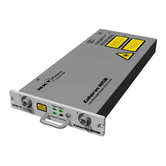
- Page 1 Koheras BASIK Low noise single frequency laser module Instruction Manual...
- Page 2 FDA (Food & Drug Administration): 21CFR 1040.10 and 1040.11 (except for deviations pursuant to Laser Notice 50, dated June 24, 2007) FDA accession number #12R0005-001 Issue: Published: April 2016 Page 2 Author: Copyright © 2016 by NKT Photonics A/S. All rights reserved. Reproduction or translations of any part of this work is prohibited.
-
Page 3: Table Of Contents
Adjustable Output Power ........................20 Optical Monitor Output ......................... 20 Thermal Tuning ........................... 21 Wavelength Modulation ........................21 5.4.1 Locking Koheras BASIK X15 to External Cavity ................. 27 Amplitude Modulation .......................... 28 Operating Mode ........................... 29 Trigger ..............................30 Auto-Start ............................31 Emission Delay and Shutdown Delay .................... -
Page 4: General
This manual covers the Koheras BASIK laser module, with the product numbers beginning with K1x2. The Koheras BASIK is a Class 3B laser and only persons who are familiar with laser safety regulations are allowed to operate these modules. WARNING: invisible radiation emitted from this laser. -
Page 5: Laser Safety
Nevertheless, its use can constitute a risk to the user or third parties or cause damage to material property. The Koheras BASIK system is not approved nor tested for use in treatment or diagnostics of human and animals and does not comply with European, US or Rest of World requirements for medical device lasers. -
Page 6: Selection And Qualification Of Personnel - Basic Responsibilities
Make sure that these labels are always complete and perfectly legible. If any labels are missing, immediately inform NKT Photonics A/S. In the event of safety relevant modifications or changes in the behavior of the Koheras BASIK during operation, stop the laser device immediately and report the malfunction to NKT Photonics A/S. -
Page 7: Physical Hazards
Despite the non-ionizing nature of the operating wavelengths, damage can still occur to living tissue as a result of heat produced during radiation absorption. All radiation of the Koheras BASIK lies outside the visible range. Suitable beam dumps must be used at all times when the laser product is operating. - Page 8 • Adhere to local and national regulations governing the safe use of lasers. Depending on system variant the Koheras BASIK system provides infrared laser emission between 900 and 2100 nm. Protective eyewear must provide sufficient protection for these wavelengths. The laser protective goggles must provide minimum OD 3+ protection.
-
Page 9: Constructive Safety Features
2.2.4 General Safety Features General Safety The Koheras BASIK is an OEM laser designed to be built into a laser system, such as e.g. a multi-channel laser system. The Koheras BASIK therefore does not have key-switch controlled laser operation. Depending on the state the laser was left in it may or may not switch on when powered up. - Page 10 Laser Source The Laser label indicates that laser light is emitted from the Koheras BASIK. Figure 2-2: Laser label Specification The Specification label provides information about what kind of laser emission is radiated from the Laser Aperture and that the Koheras BASIK product complies with the IEC 60825-1 standard.
-
Page 11: Label Positions
The positions of safety labels and silk screen on the top cover and front are shown on figure 2-6. top cover view front view Figure 2-6: Safety labels on the top cover and front of the Koheras BASIK Page 11... -
Page 12: Requirements
3 Requirements Room Requirements The Koheras BASIK is a Class 3B laser product and the operation room and operation conditions need to comply with the following requirements: • CFR21 1040.10 & Laser Notice LN50 • IEC / EN 60825-1 Alternatively the Koheras BASIK should be operated in accordance with local regulations for a Class 3B laser source. -
Page 13: Interface
4.1.1 Optical Output(s) Optical Outputs The Koheras BASIK module has either one or two optical outputs (marked with an ‘A’ and a ‘B’ on the front of the module). One holds the primary optical output, while the other is a secondary monitor optical output (optional). The allocation of ‘A’ and ‘B’... -
Page 14: Leds
4.1.2 LEDs The front panel holds four LEDs which indicate different states. Figure 4-2: LEDs Interlock Green: Interlock status is okay Red: Interlock status is not okay Power Off: module is not powered up Red: supply voltage low Green: supply voltage OK Flashes yellow: module is transmitting data Emission Off: no emission from the module... -
Page 15: Handle
4.1.3 Handle The Koheras BASIK features a small handle in the front. This handle is for e.g. pulling the module out from a Koheras ACOUSTIK frame. Figure 4-3: Handle 4.1.4 Front Mounting Holes The front plate of the Koheras BASIK has two mounting holes, which fit with M3 screws. -
Page 16: Rear Panel
The electrical interface on the Koheras BASIK module features power supply for the module, digital communication, interlock signals, modulation input/outputs, etc. The connector used in the Koheras BASIK for the electrical interface is a 30 pins DIN41612 male C/3 type. - Page 17 Positive branch of differential input/output for Wavelength+ wavelength/wavelength modulation. A5, A6, 0 volt / ground. B5, B6, C5, C6 A7, A8, + 12 volt supply voltage for Koheras BASIK module. B7, B8, C7, C8 Table 4-1: Electrical interface pin-out Page 17...
-
Page 18: Heat Transfer Surface
A DIN 41612 female Type C/3 should be used to interface with the Koheras BASIK. 4.2.2 Heat Transfer Surface Heat Transfer Heat generated in the Koheras BASIK module should be transferred to the Surface environment. Next to the electrical interface on the back of the module is a 20 mm x 50 mm surface, which has to interface with proper heat sinking to the environment. -
Page 19: Guiding Hole
The two outer holes on the heat transfer surface are M4 holes that can be used for mounting and fixation of the Koheras BASIK module. Please refer to the mechanical drawing at the end of this document for specifications on the actual positions of the mounting holes. -
Page 20: Features And Functions
Registers For Koheras BASIK modules that can have their output power adjusted, this is done with either register 0x22 or 0xA0 in mW or dBm respectively. 5.2 Optical Monitor Output Optical Monitor The Koheras BASIK module has as an option an optical monitor output. -
Page 21: Thermal Tuning
0x2A. 5.4 Wavelength Modulation Wavelength modulation is an option for Koheras BASIK. Laser modules that include this option can be modulated with an electrical input signal, an internal function generator or both. - Page 22 The common mode voltage for the input signal should be 2.5 V. Single-ended to The circuit below shows an example how to generate a differential signal from a Differential single-ended input. In this example a single-ended input signal with 5 Vpp and a common-mode voltage at 0 V will generate a 2x 5 Vpp differential signal with a common mode voltage at 2.5 V.
- Page 23 Figure 5-4: Single-ended input connections with 2.5 V on unused branch If the Wavelength- signal is connected to GND but the Wavelength+ signal is modulated between 0 and 5 V, the optical output is only modulated above its thermally controlled wavelength. Time Figure 5-5: Single-ended input signal with GND on unused branch Figure 5-6: Single-ended input connections with 0 V on unused branch...
- Page 24 AC coupling is chosen, the module has a high pass filter function with cut-off frequency at 1.6 Hz. Setting the Koheras BASIK X15 to DC coupling makes it possible to lock the laser to an external reference using e.g. the Pound Drever Hall technique. In this mode the module will adjust its wavelength so the differential error signal on the Wavelength+/- input goes towards 0 V.
- Page 25 Koheras BASIK X15 has 500 MHz tuning at low frequencies in Wide range with smooth roll-off with a 3 dB cut-off at 300 Hz. In Narrow range Koheras BASIK X15 has 30 MHz tuning with small peaking at ~3 kHz.
- Page 26 External and Internal The wavelength of the Koheras BASIK module can be modulated with either an external Wavelength electrical signal applied to the Wavelength+/- input, with the internal function generator or Modulation both. The firmware in the module is designed so at least one of the two is enabled.
-
Page 27: Locking Koheras Basik X15 To External Cavity
5.4.1 Locking Koheras BASIK X15 to External Cavity The Koheras BASIK X15 can be locked to an external cavity e.g. to obtain even lower low-frequency phase noise by using the Pound-Drever-Hall technique. Phase Beam External modulator splitter cavity BASIK X15... -
Page 28: Amplitude Modulation
5.5 Amplitude Modulation K1x2 Koheras BASIK modules with the VOA option also have the possibility for Amplitude Modulation. The laser modules can be modulated with an electrical input signal or an internal function generator. Modulation of the output power is relative to the output power setpoint, which determines the 100% level. -
Page 29: Operating Mode
0x31 bit 9 where ‘0’ means internal function generator and ‘1’ means external signal. Modulation If the Koheras BASIK module is set to modulate the output power with its internal Frequency function generator the modulation frequency can be varied between 0.008 Hz and up to maximum 10 kHz. -
Page 30: Trigger
5.7 Trigger The K1x2 Koheras BASIK module has a Trigger logic input/output signal in the electrical interface. This Trigger signal can be used to either initiate or indicate laser emission. The signal is active high, i.e. if the Trigger is used as input to initiate laser emission a positive voltage must be applied. -
Page 31: Auto-Start
5.9 Emission Delay and Shutdown Delay Emission Delay The Koheras BASIK module has a so-called Emission Delay register, which is set to 1.5 seconds. When emission is initiated the emission LED on the front of the module and the Emission output in the electrical interface will indicate emission right away, but laser light is not emitted until 1.5 seconds later. -
Page 32: Interface Board
6 Interface Board If desired the Koheras BASIK can interface directly with a system mainboard if this has the DIN 41612 female C/3 connector. However for some it may be desired to use the Interface board. Contact NKT Photonics about availability. - Page 33 Extra I/O Miscellaneous connections, e.g. for pull-up of Enable and Interlock signals if the Koheras BASIK should be used without the Interbus interface. 6-pin IDC connector. Pin no. Name Description Logic input/output. Requires external pull-up resistor when Trigger used as output. See Trigger for more details.
-
Page 34: Recommended Mounting
7 Recommended Mounting The Koheras BASIK is designed to be used both as plug-in module for the Koheras ACOUSTIK system and as a stand-alone module. If the module should be used as a stand-alone module the figure below shows the recommended way of mounting. -
Page 35: Operation
Use the following procedure to turn the system on. Step Procedure Mount the Koheras BASIK module where it should be used with mechanical/thermal contact to an external heat sink. Connect the optical output from the Koheras BASIK to its point of use. -
Page 36: Computer Controlled Operation
9 Computer Controlled Operation Graphical User The Koheras BASIK can be controlled from a computer via the NKT Photonics Interface CONTROL software. Please refer to the manual for NKT Photonics CONTROL for details on installing and operating this software. NKT Photonics CONTROL can be downloaded from our website on: http://www.nktphotonics.com/support/software-drivers/... -
Page 37: Module Dimensions
11.1 Module Dimensions Page 37... -
Page 38: Dimensions With Adaptor Board
11.1 Dimensions with Adaptor Board Page 38... - Page 39 This page intentionally left blank Page 39...
- Page 40 NKT Photonics A/S Blokken 84 3460 Birkerød Denmark Phone: +4543483900 Fax: +4543483901 Page 40 www.nktphotonics.com...
Need help?
Do you have a question about the Koheras BASIK and is the answer not in the manual?
Questions and answers