Sign In
Upload
Manuals
Brands
Nilfisk-Advance Manuals
Scrubber
Liberty SC50 X20R
Nilfisk-Advance Liberty SC50 X20R Manuals
Manuals and User Guides for Nilfisk-Advance Liberty SC50 X20R. We have
2
Nilfisk-Advance Liberty SC50 X20R manuals available for free PDF download: Service Manual, Instructions For Use Manual
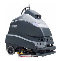
Nilfisk-Advance Liberty SC50 X20R Service Manual (350 pages)
Brand:
Nilfisk-Advance
| Category:
Scrubber
| Size: 29 MB
Table of Contents
Table of Contents
2
Drive Controller Error Code Index
3
03 - General Information
8
General Machine Description
8
Service Manual Purpose and Application
8
Other Reference Manuals and Information Sources
8
Parts and Service
8
Diagnostic and Service Tools
8
Conventions
9
Revision History
9
Parts and Service
9
Modifications
9
Nameplate
9
Safety
10
General Safety Instructions
10
Symbols
10
Lithium-Ion Battery Specific Safety Instructions
11
Property Damage Messages
11
Lifting or Transporting the Machine
12
Moving a Disabled Machine
13
Control Cover Prop Rod
13
Specifications
14
General Specifications
14
Overall Dimensions
15
Fastener Torque Specifications
16
Maintenance
16
Maintenance Schedule
16
Lubrication Locations
17
Maintenance Procedure References
17
Preventive Maintenance Checklist - Liberty SC50
18
Major Machine Components
24
04 - Control System
25
Functional Description
25
Functional Block Diagram
25
Onboard Charger
27
Power Module
27
Wheel Drive Controller
28
Main Machine Controller
29
Control Panel
30
CAN Bus Communication
31
CAN Bus Information
32
Component Locations
33
Main Machine Controller Menus
34
Menu Navigation
34
Service Mode Access (from Power-Off)
34
Service Mode Access (While Powered-On)
34
Menu Outline
35
Authorizing User Keys
37
Deauthorizing User Keys
37
Faults Menu
37
Hours Menu
37
Keys Menu
37
A1 Main Machine Controller
38
Service Menu
38
A2 Power Module
39
A3 Drive Controller
39
A4 Steering Controller
40
A5 Autonomy
40
A8 Battery Charger
41
B1 Li-Ion Battery Menu
42
Output Test
44
Factory Resets
45
Panel Test
45
Options Menu
46
Autonomous Cleaning Menu
49
Configuration Menu
49
Maintenance and Adjustments
50
MMC Firmware Update Via USB
50
Troubleshooting
51
Rebooting
51
Terminology
51
Error Code Index
52
Main Machine Controller (E2) Error Codes
54
Power Module (A2) Error Codes
71
Removal and Installation
89
Control Panel/Main Machine Controller
89
Specifications
90
Sample Shop Voltage Measurements
90
Device Resistances
93
Motor Amp Draw Measurements
93
05 - Autonomous System
95
Functional Description
95
Functional Block Diagram
95
LED Status Bar
96
Drive Wheel Angle Sensor
97
IOT (Communication) Module
97
Wheel Encoders
97
3D Vision Sensor
98
Pattern Projector
98
Drop-Off Sensors
99
Mapping Sensor (Laser)
99
Safety Sensors (Lasers)
102
Area Address Selection
103
Warning and Protection Zones
103
Master-Slave Communication
104
Outputs and LED Indicators
104
Component Locations
105
Maintenance and Adjustment
106
Wheel Encoder Gap
106
Drive Wheel Angle Sensor Centering
107
Drop-Off Sensor Calibration
108
3D Vision Sensor (Camera) Calibration
109
2D Mapping (Sensor) Laser Calibration
110
2D Mapping Sensor Level Check and Adjust
110
Checking Laser Level
113
Left Safety Sensor Level Check and Adjust
113
Right Safety Sensor Level Check and Adjustment
116
Right Safety Sensor - Check Maximum Laser Height
119
Safety Sensor Rotational Position Check (Right and Left)
121
Safety Sensor Rotational Position Adjustment
122
Autonomous Controller and Main Machine Controller Software Update
125
Connect to Wifi
126
Downloading and Installing Software Updates
126
Autonomous System Safety Testing
127
Locking Machine out of Autonomous Operation
127
Static Test of Drop-Off Sensors
127
Dynamic Floor Drop-Off Simulation
129
Safety (Laser) Sensor Performance Tests
132
Straight-Line Test Setup
132
High Speed Stop
133
Stay-Put Test
133
Forward Low Speed Stop
135
Right Turning Low Speed Stop
139
Left Turning Low Speed Stop
140
Troubleshooting
142
Troubleshooting Flow Chart
142
Drive Wheel Angle Sensor
143
Sensor Input Validation Testing
143
Safety Sensors (Left and Right)
144
2D Mapping Sensor
145
Vision Sensor (Camera)
145
Drop-Off Sensors
146
Rear Wheel Encoders
147
Rebooting
147
Safety Sensor Error Codes
148
Autonomous System Error Code Reference
149
Removal and Installation
150
Autonomy Module
150
3D Vision Sensor
152
2D Mapping Sensor
154
Left Safety Sensor
156
Right Safety Sensor
157
Drop-Off Sensors
158
Drive Wheel Angle Sensor
159
Specifications
161
Sample Shop Voltage Measurements
161
Special Tools
164
10-Chassis System
165
Functional Description
165
Removal and Installation
166
Tipping the Machine
166
20 - Wheel System - Traction
168
Functional Description
168
Wheel Drive Controller
169
Drive Control
170
Manual Speed Control
170
Component Locations
171
Maintenance and Adjustment
172
Wheel Motor Brushes
172
Drive Chain Maintenance and Adjustment
173
Troubleshooting
174
Terminology
174
Drive Controller Error Code Index 3-001
175
Drive Controller Error Codes
176
Excess M1 Drv Whl Mtr Current
176
A3 Calibration Reset
177
Internal Clock Failure
177
Driver 1Or2 Ovrcrnt
178
K3 Cntctr Coil Open
178
A3 EEPROM Fault
179
Emrgcy Reverse Fault
179
K3 Contact Not Closing
180
K3 Contactor Closed
181
M1/M2 Outputs Shorted
181
Lost Comm-A1 Mn Cntrlr
182
A3 Supervisor Comm
183
A3 Supervisor Watchdog
183
Auto OK Input Fault
183
Go Pedal (POT 1) Fault
183
Output Fault
183
S1 Operator Pr Sw Flt
183
S2 E-Stop Fault
183
Spd Lmt (POT 2) Fault
183
Steer Ready Input Flt
183
Supervisor Pot3 Fault
183
EM Brake Open
184
External Supply Fault
184
Brake Driver on
185
Pot 1 Range
185
Pot 2 Range
185
Pot 3 Fault
186
Very Low Cntrlr Temp
186
Very Low Voltage
186
K3 Cntr/Y1 Brk Shorted
187
Low B+ Power Input
187
Very High Cntrlr Temp
187
Correlation Fault
188
Driver3 Fault
188
Driver3 Overcurrent
188
Driver4 Fault
188
Driver4 Overcurrent
188
Driver5 Fault
188
Driver5 Overcurrent
188
Driver6 Fault
188
Driver6 Overcurrent
188
Go Pedal Switch Closed
188
A3 Drive Motor Hot
189
A3 NV Memory Fault
189
Parameter Change
189
M1 Drive Motor Open
190
M1 Drive Motor Short
190
High Voltage
191
Low Temperature Cutback
191
Stall Detected
191
A3 Drv Cntrl Temp High
192
High Voltage
192
Removal and Installation
194
Drive Assembly
194
Drive Wheel Motor
196
Drive Wheel and Wheel Bearings
197
Specifications
199
Sample Shop Voltage Measurements
199
22 - Steering System
201
Functional Description
201
Steering Controller
202
Steering Actuator
204
Steering Wheel Position Sensor
204
Maintenance and Adjustment
205
Steering Spindle Bearings
205
Steering Chain Maintenance and Adjustment
207
Drive Wheel Angle Sensor Centering
208
Troubleshooting
209
Rebooting
209
Terminology
209
Steering Controller Error Codes
210
Removal and Installation
225
Steering Controller Module
225
Steering Sensor
225
Steering Controller and Actuator
226
Sample Shop Voltage Measurements
228
Specifications
228
24 - Electrical System
229
Functional Description
229
Fuses and Circuit Breakers
229
K2 and K3 Relays
230
KSI Relay
230
E-Stop Switch
231
Low Voltage Cutout
231
Onboard Battery Charger
231
DC/DC Converter
232
Li-Ion Technical Data
232
Lithium-Ion Battery Option
232
Ultraviolet Germicidal Irradiation (UVGI) Option
232
Component Locations
233
Maintenance and Adjustments
234
Battery Charging Profile (Algorithm) Setting
234
Troubleshooting
235
Back-Probing Connector Voltages
235
General Electrical Troubleshooting
235
Testing Cables
236
Connector Probe Kit
237
Battery Charger Error Codes
238
Finding LL-Codes
248
Lithium-Ion Battery Error Codes
248
Lower-Level Codes (0X##)
248
Machine-Level Codes (10-1Xx)
248
Upper-Level Codes (10-2Xx)
248
Removal and Installation
261
Operator Platform
261
Platform Switches
262
Batteries (Lead-Acid)
263
Batteries (Lithium Ion)
264
Battery Charger
267
Wiring Diagrams
268
Understanding the Features of the Electrical Circuit Diagram
268
Splice Points
270
Using the Wiring Harness Diagram
270
Wire Numbers
270
Acrobat Search to Trace a Circuit
271
Connector Numbers
271
Electrical Circuit Diagram
272
Sheet 1, Main Machine Controller
272
Sheet 2, Power Module
273
Sheet 3, Drive Controller
274
Sheet 4, Steering Controller
275
Sheet 5, Autonomy Controller
276
Sheet 6, Autonomy Breakout Box
277
Sheet 7, UVGI Option, Generation 2
278
Sheet 8, UVGI Option, Generation 3
279
Sheet 9, Battery Connection Options
280
56104984, Rev F, for Legacy Models
281
Wiring Harness Diagrams
281
56104911, Rev B, for Focus Release Models
286
3D Harness Diagrams
291
Main Harness, Autonomy Bay
292
Main Harness, Main Machine Controller
292
Main Harness, Electrical Bay
293
Power Connections, Electrical Bay
293
Main Harness, Lower Electrical Bay
294
Main Harness, Rear Platform
295
Main Harness, Scrub Deck
295
Autonomy Cables, Autonomy Bay
296
Autonomy Cables, Mapping and Safety Lasers
297
Autonomy Cables, Dropoff Sensors
298
Electrical Connector Pin-Out Assignments
299
30 - Solution System
315
Functional Description
315
Circuit Description
316
Detergent Pump
317
Solution Flow Meter
317
Maintenance and Adjustments
318
Cleaning the Solution Filter
318
Draining the Solution Tank
318
Clean and Inspect the Solution Solenoid
319
Removal and Installation
320
Solution Pump
320
Detergent Pump
321
Specifications
321
Component Specifications
321
Nominal Solution Flow Rates
321
34-Scrub System
322
Functional Description
322
Functional Diagram
322
Deck Lift Actuator
323
Deck Types
323
Maintenance and Adjustment
325
Scrub Deck Actuator Adjustment
325
Troubleshooting
327
Uneven Cleaning Path
327
Removal and Installation
328
Scrub Deck
328
Scrub Deck Actuator Assembly
330
Motor Brushes (Disc Deck)
332
Motor Brushes (Rev Deck)
333
Rev Deck Bearing and Motor
335
Specifications
337
38-Squeegee System
338
Functional Description
338
Maintenance and Adjustment
339
Squeegee Blade Replacement
339
Troubleshooting
340
40-Recovery System
341
Functional Description
341
Circuit Description
342
Troubleshooting
343
General Troubleshooting
343
Vacuum Suction Test
345
Removal and Installation
346
Recovery Tank
346
Recovery Tank Float Switch
347
Vacuum Motor
348
Vacuum Motor Brushes
349
Specifications
350
Special Tools
350
Advertisement
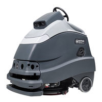
Nilfisk-Advance Liberty SC50 X20R Instructions For Use Manual (132 pages)
Brand:
Nilfisk-Advance
| Category:
Scrubber
| Size: 38 MB
Table of Contents
English
2
Table of Contents
2
Introduction
2
Parts and Service
3
Modifications
3
Name Plate
3
Uncrate the Machine
3
Transporting the Machine
3
Cautions and Warnings
4
Regulatory
9
Know Your Machine
10
Control Panel
12
Information Menu Display
15
Autonomous Help Screen
19
Understanding Autonomy
20
Install the Batteries
21
Prepare the Machine for Use
21
Batteries
21
Location Tag
22
Location Tag Position
23
Magnetic Smartkey
25
Install the Brush (Disc System)
26
Install the Pad (REV System)
27
Install the Squeegee
28
Fill the Solution Tank
29
Solution Tank Indicator
29
Detergent System Preparation (Ecoflex)
30
Detergent System Purge
31
Detergent System Use (Ecoflex)
32
Starting the Machine
34
Operating the Machine
34
Stopping the Machine
36
Recording Plans for Autonomous Mode
37
Recording Copycat™ Plans
38
Recording Fill-In Plans
40
Playback of Recorded Plan, Autonomous Mode
45
LED Status Bar Operation
48
Speaker Operation
49
Operating the Machine Manual Mode
50
After Use
52
Maintenance
53
Maintenance Schedule
53
Cleaning Recovery Tank
53
Cleaning Solution Filter
54
Clean Sensor Lenses
54
Lubricating the Machine
55
Electromagnetic Brake
55
Charging GEL/AGM (VRLA) Batteries
56
Squeegee Maintenance
58
Squeegee Adjustment
58
Troubleshooting
59
General Machine Troubleshooting
59
Autonomous Mode Troubleshooting
60
Fault Code Display
61
Fault Code History
62
Specifications
63
Accessories / Options
63
Material Composition and Recyclability
63
Solution Flow Rates
63
Technical Specifications
64
Glossary
65
Español
66
Introducción
66
Desembalaje de la Máquina
67
Modificaciones
67
Piezas y Servicio
67
Placa de Identificación
67
Transporte de la Máquina
67
Precauciones y Advertencias
68
Normativa
73
Conozca Su Máquina
74
Panel de Control
76
Pantalla del Menú de Información
79
Pantalla de Ayuda Modo Autónomo
83
Conocimiento de la Autonomía
85
Baterías
86
Instalación de las Baterías
86
Preparación de la Máquina para Su Uso
86
Etiqueta de Ubicación
87
Posición de la Etiqueta de Ubicación
88
Smartkey™ Magnética
90
Instalación del Cepillo (Sistema de Disco)
91
Instalación del Fieltro (Sistema REV)
92
Instalación del Limpiador
93
Indicador del Depósito de Solución
94
Llenado del Depósito de Solución
94
Preparación del Sistema de Detergente (Ecoflex)
95
Purga del Sistema de Detergente
96
Uso del Sistema de Detergente (Ecoflex)
97
Funcionamiento de la Máquina
99
Puesta en Marcha de la Máquina
99
Detención de la Máquina
101
Planes de Grabación para el Modo Autónomo
102
Grabación de Los Planes Copycat
103
Grabación de Planes Llenado
105
Reproducción del Plan Registrado, Modo Autónomo
110
Funcionamiento de Los Altavoces
113
Funcionamiento LED Barra de Estado
113
Funcionamiento de la Máquina en Modo Manual
114
Después del Uso
116
Limpieza del Depósito de Recuperación
117
Mantenimiento
117
Programa de Mantenimiento
117
Limpiar las Lentes del Sensor
118
Limpieza del Filtro de la Solución
118
Cómo Lubricar la Máquina
119
Freno Electromagnético
119
Carga de las Baterías de GEL/AGM (VRLA)
120
Ajuste del Limpiador
122
Mantenimiento del Limpiador
122
Resolución de Problemas
123
Resolución de Problemas Generales de la Máquina
123
Resolución de Problemas del Modo Autónomo
124
Pantalla de Códigos de Averías
125
Histórico de Códigos de Averías
126
Accesorios/Opciones
127
Caudales de la Solución
127
Composición de Materiales y Reciclabilidad
127
Especificaciones
127
Especificaciones Técnicas
128
Glosario
129
Advertisement
Related Products
Nilfisk-Advance SC500
Nilfisk-Advance Liberty SC50
Nilfisk-Advance Advance SC5000
Nilfisk-Advance Liberty SC50 X20D
Nilfisk-Advance SC530 53 BD GO
Nilfisk-Advance SC550 Series
Nilfisk-Advance SC550 20D
Nilfisk-Advance SC550 24D
Nilfisk-Advance SC550 20C
Nilfisk-Advance SC550 20R
Nilfisk-Advance Categories
Vacuum Cleaner
Floor Machine
Scrubber
Pressure Washer
Blower
More Nilfisk-Advance Manuals
Login
Sign In
OR
Sign in with Facebook
Sign in with Google
Upload manual
Upload from disk
Upload from URL