Sign In
Upload
Manuals
Brands
National Instruments Manuals
PCI Card
6715
User Manuals: National Instruments 6715 Output Card
Manuals and User Guides for National Instruments 6715 Output Card. We have
1
National Instruments 6715 Output Card manual available for free PDF download: User Manual
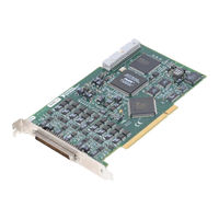
National Instruments 6715 User Manual (84 pages)
Analog Voltage Output Device for PCI/PXI/CompactPCI/PCMCIA/1394 Bus Computers
Brand:
National Instruments
| Category:
PCI Card
| Size: 3 MB
Table of Contents
Table of Contents
5
About this Manual
8
Conventions Used in this Manual
8
National Instruments Documentation
9
Related Documentation
10
Chapter 1 Introduction
11
About the 671X Devices
11
Using PXI with Compactpci
12
What You Need to Get Started
13
Table 1-1. PXI-6711/6713 J2 Pin Assignment
13
Unpacking
14
Software Programming Choices
14
National Instruments Application Software
14
NI-DAQ Driver Software
15
Register-Level Programming
16
Appendix C
16
Figure 1-1. the Relationship between the Programming Environment, NI-DAQ, and Your Hardware
16
Custom Cabling
17
Optional Equipment
17
Chapter 2 Installation and Configuration
18
Software Installation
18
Hardware Installation
18
Device Configuration
21
Chapter 3 Hardware Overview
22
Figure 3-1. 6711/6713 Block Diagram
23
Figure 3-2. 6715 Block Diagram
24
Analog Output
25
Analog Output Reference Selection
25
Analog Output Reglitch Selection
25
Digital I/O
25
Timing Signal Routing
26
Figure 3-3. UPDATE* Signal Routing
26
Device and RTSI Clocks
27
Programmable Function Inputs
27
Figure 3-4. RTSI Bus Signal Connection
28
RTSI Triggers
28
Chapter 4 Signal Connections
29
I/O Connector
29
Figure 4-1. 68-Pin I/O Connector Pin Assignment for the 671X Device
30
Figure 4-2. 50-Pin I/O Connector Pin Assignment for the 671X Device When Using the SH68-50 Cable
31
I/O Connector Signal Descriptions
32
Table 4-1. Signal Descriptions for I/O Connector Pins
32
Table 4-2. I/O Signal Summary for the 6711/6713 Device
34
Analog Output Signal Connections
35
Digital I/O Signal Connections
37
Figure 4-3. Analog Output Connections
37
Figure 4-4. Digital I/O Connections
38
Power Connections
39
Timing Connections
39
Figure 4-5. Timing I/O Connections
40
Programmable Function Input Connections
41
EXTSTROBE* Signal
41
Waveform Generation Timing Connections
42
WFTRIG Signal
42
Figure 4-6. WFTRIG Input Signal Timing
42
UPDATE* Signal
43
Figure 4-7. WFTRIG Output Signal Timing
43
Figure 4-8. UPDATE* Input Signal Timing
43
UISOURCE Signal
44
Figure 4-9. UPDATE* Output Signal Timing
44
Figure 4-10. UISOURCE Signal Timing
44
General-Purpose Timing Signal Connections
45
GPCTR0_SOURCE Signal
45
Figure 4-11. GPCTR0_SOURCE Signal Timing
45
Figure 4-12. GPCTR0_GATE Signal Timing in Edge-Detection Mode
46
GPCTR1_SOURCE Signal
47
Figure 4-13. GPCTR0_OUT Signal Timing
47
GPCTR1_GATE Signal
48
Figure 4-14. GPCTR1_SOURCE Signal Timing
48
Figure 4-15. GPCTR1_GATE Signal Timing in Edge-Detection Mode
49
Figure 4-16. GPCTR1_OUT Signal Timing
49
GPCTR1_UP_DOWN Signal
50
Figure 4-17. GPCTR Timing Summary
50
FREQ_OUT Signal
51
Field Wiring Considerations
51
Chapter 5 Calibration
52
Loading Calibration Constants
52
Self-Calibration
53
External Calibration
53
Other Considerations
54
Appendix A Specifications
55
Advertisement
Advertisement
Related Products
National Instruments 6035E
National Instruments 6034E
National Instruments 6509
National Instruments 6711
National Instruments 6713
National Instruments 6722
National Instruments 6723
National Instruments 6733
National Instruments 6731
National Instruments 6738
National Instruments Categories
Control Unit
I/O Systems
Controller
Computer Hardware
Measuring Instruments
More National Instruments Manuals
Login
Sign In
OR
Sign in with Facebook
Sign in with Google
Upload manual
Upload from disk
Upload from URL