Sign In
Upload
Manuals
Brands
MTU Manuals
Engine
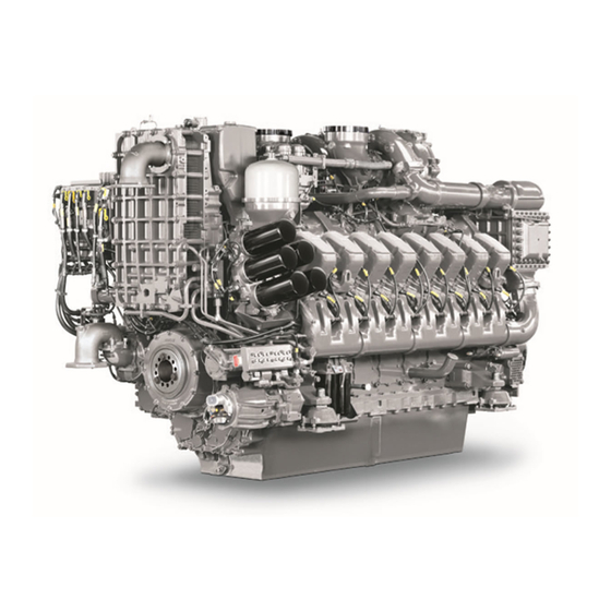
16 V 4000 M63L
MTU 16 V 4000 M63L Manuals
Manuals and User Guides for MTU 16 V 4000 M63L. We have
1
MTU 16 V 4000 M63L manual available for free PDF download: Operating Instructions Manual
MTU 16 V 4000 M63L Operating Instructions Manual (262 pages)
Brand:
MTU
| Category:
Engine
| Size: 49 MB
Table of Contents
Operating Instructions
1
Table of Contents
5
1 Safety
7
General Information
7
Important Provisions for All Products
7
Nameplate
7
Organizational Measures of the Operator
8
Personnel and Organizational Requirements
8
Personnel Requirements
8
Working Clothes and Personal Protective Equipment
8
Setting the Engine down after Transport
9
Transport
9
Safety Regulations During Maintenance and Repair Work
10
Safety Regulations for Maintenance and Repair Work
10
Hydraulic Installation and Removal
11
Safety Regulations after Completion of Maintenance and Repair Work
11
Welding Work
11
Working with Batteries
11
Working on Electrical and Electronic Assemblies
12
Working with Laser Equipment
12
Environmental Protection and Disposal
13
Fire Prevention and Environmental Protection, Fluids and Lubricants, Auxiliary Materials
13
Noise
13
Compressed Air
14
Lead
14
Liquid Nitrogen
14
Paints and Varnishes
14
Standards for Safety Notices in the Text
15
Engine Layout
16
Fuel System
16
Product Description
16
Electronic System
17
Engine Interface Module (EIM)
17
Functions
17
Intermittent Oil Priming for Marine Genset Engines
17
1 Low-Load Operation
18
Electronic Engine Governor (ECU)
18
Electronic Engine Monitoring Unit (EMU)
18
Low-Load Operation
18
12/16V4000M23S/M23F/M33S/M33F/M43S Engines
19
SOLAS – Fire Protection Specifications
19
Plug-In Pipe Union
26
Plugs and Sensors
26
HP Connections
27
Engine Layout
28
Engines with Remote Heat Exchanger and Horizontal Air Intake
28
Engines with Engine-Mounted Heat Exchanger and Horizontal Air Intake
29
Engines with Remote Heat Exchanger and Vertical Air Intake
30
Engine Model Designation
31
Engines with Engine-Mounted Heat Exchanger and Vertical Air Intake
31
Sensors, Actuators and Injectors on 16V Engines – Overview
32
Top View 16V 4000 M, External Cooling
32
16V 4000 M Free End, External Cooling
33
16V 4000 M Driving End, External Cooling
34
16V 4000 M Left Side, External Cooling
35
16V 4000 M Right Side, External Cooling
36
Top View 16V 4000 M, Integral Cooling
37
16V 4000 M Free End, Integral Cooling
38
16V 4000 M Driving End, Integral Cooling
39
16V 4000 M Left Side, Integral Cooling
40
16V 4000 M Right Side, Integral Cooling
41
2 Product Summary
16
Engine Side and Cylinder Designations
42
Main Engine Dimensions
43
4000 M63L Engines - Main Dimensions
43
Firing Sequence
44
Firing Order
44
Technical Data
45
4000 M63L Engine Data
45
General Conditions
45
Power-Related Data
45
General Operating Data
46
Lube-Oil System
46
Raw Water Circuit
46
Capacities
47
Inclinations, Standard Oil System
47
Starting
47
Acoustics
48
Weights / Main Dimensions
48
Automation System Controls
49
Controls
49
3 Operation
49
Preconditions
50
Putting the Engine into Operation after Extended Out-Of-Service Periods (>3 Months)
50
Putting the Engine into Operation after Scheduled Out-Of-Service-Period
51
Starting the Engine
52
Operational Checks
53
Tasks after Extended Out-Of-Service Periods (>3 Weeks)
54
Checks Prior to Start-Up
55
Fuel Treatment System – Putting into Operation
56
Overview of Fuel Treatment System
56
Switching on Fuel Treatment System
56
Initial Operation: hat
57
Simulation of Filter Replacement with the Engine Running: hat
57
Simulation of Power Failure (Emergency): hat
57
Simulation of Power Failure (Emergency): SAT
58
Fuel Treatment System – Switching on
59
Fuel Treatment System – Shutdown
60
Shutting down Fuel Treatment System
60
Stopping the Engine
61
Stopping the Engine Via the Automation System
61
Emergency Engine Stop
62
After Stopping the Engine
63
Plant – Cleaning
64
Special Tools, Material, Spare Parts
64
Maintenance Task Reference Table [QL1]
65
Engine Does Not Turn When Starter Is Actuated
67
Engine Fires Unevenly
67
Engine Turns on Starting but Does Not Fire
67
5 Troubleshooting
67
Charge-Air Pressure too Low
68
Charge-Air Temperature too High
68
Coolant Leaks at Intercooler
68
Engine Speed Not Steady
68
White Exhaust Gas
69
Fuel Treatment System - Troubleshooting
70
Illuminated Pushbutton 'Water Alarm' Is Lit
70
Signal Lamp 'Pre-Alarm' Is Lit
70
Signal Lamp 'Pump Fault' Is Lit
70
Engine Governor ADEC (ECU 7) Fault Messages for Series 4000 Engines, Marine Application
71
Engine Governor ADEC (ECU 7) – Fault Codes
72
HI T-Charge Air
72
HI T-Fuel
72
SS T-Fuel
72
HI T-Coolant Charge-Air Cooler
73
LO P-Lube Oil
73
SS P-Lube Oil
73
SS T-Coolant Charge-Air Cooler
73
HI T-Exhaust a
74
HI T-Exhaust B
74
SS T-Exhaust a
74
SS T-Exhaust B
74
HI ETC Idle Speed too High
75
HI Level Leakage Fuel
75
HI P-Diff. Lube Oil
75
SS Engine Overspeed
75
HI ETC1 Overspeed
76
HI P-Diff-Fuel
76
SS ETC1 Overspeed
76
SS P-Diff-Fuel
76
AL ETC Speed Deviation
77
AL ETC2 Cut-In Fault
77
LO Coolant Level Charge-Air Cooler
77
SS ETC2 Overspeed
77
LO P-Coolant
78
SS P-Coolant
78
SS T-Coolant L3
78
SS T-Lube Oil
78
HI P-Crankcase
79
LO P-Fuel
79
SS P-Crankcase
79
SS T-Coolant L4
79
AL Rail Leakage
80
HI T-Coolant
80
SS P-Fuel
80
SS T-Coolant
80
HI P-Fuel (Common Rail)
81
HI T-Recirculation
81
LO P-Fuel (Common Rail)
81
SS T-Recirculation
81
90 – SS Starter Speed Not Reached
82
91 – SS Release Speed Not Reached
82
92 – SS Starter Speed Not Reached
82
93 – SS T-Preheat
82
102 – al Fuel Cons. Counter Defect
83
104 – al Eng Hours Counter Defect
83
118 – lo ECU Power Supply Voltage
83
95 – al Prelubrication Fault
83
120 – HI ECU Power Supply Voltage
84
121 – HIHI ECU Power Supply Voltage
84
122 – Hi T-Ecu
84
141 – al Power too High
84
176 – al Lifedata Not Available
85
177 – al Lifedata Restore Incomplete
85
180 – al CAN1 Node Lost
85
181 – al CAN2 Node Lost
85
182 – al CAN Wrong Parameters
86
183 – al CAN no PU-Data
86
184 – al CAN PU-Data Flash Error
86
186 – al CAN1 Bus off
86
187 – al CAN1 Error Passive
87
188 – al CAN2 Bus off
87
189 – al CAN2 Error Passive
87
190 – al EMU Parameter Not Supported
87
201 – SD T-Coolant
88
202 – SD T-Fuel
88
203 – SD T-Charge Air
88
204 – SD Level Lube Oil
88
205 – SD T-Coolant Charge-Air Cooler
89
206 – SD T-Exhaust a
89
207 – SD T-Exhaust B
89
208 – SD P-Charge Air
89
211 – SD P-Lube Oil
90
212 – SD P-Coolant
90
213 – SD P-Coolant Charge-Air Cooler
90
214 – SD P-Crankcase
90
215 – Sd P-Hd
91
216 – SD T-Lube Oil
91
219 – SD T-Intake Air
91
220 – SD Level Coolant Water
91
221 – SD P-Diff Lube Oil
92
222 – SD Level Leak-Off Fuel
92
223 – SD Level Coolant Charge-Air Cooler
92
227 – SD P- Lube Oil before Filter
92
228 – SD P-Fuel before Filter
93
229 – al Stop Camshaft Sensor Defect
93
230 – SD Crankshaft Speed
93
231 – SD Camshaft Speed
93
232 – SD Charger 1 Speed
94
233 – SD Charger 2 Speed
94
239 – SD P-Diff Fuel
94
240 – SD P-Fuel
94
241 – SD T-Recirculation
95
242 – SD T-Coolant (R)
95
244 – SD P-Lube Oil (R)
95
245 – SD ECU Power Supply Voltage
95
268 – SD Spinning Value
96
269 – SD Loadp.analog Filt.
96
270 – SD Frequency Input
96
301 – al Timing Cylinder A1
96
303 – al Timing Cylinder A3
97
304 – al Timing Cylinder A4
97
305 – al Timing Cylinder A5
97
306 – al Timing Cylinder A6
97
309 – al Timing Cylinder A9
98
310 – al Timing Cylinder A10
98
311 – al Timing Cylinder B1
98
312 – al Timing Cylinder B2
98
315 – al Timing Cylinder B5
99
316 – al Timing Cylinder B6
99
317 – al Timing Cylinder B7
99
318 – al Timing Cylinder B8
99
321 – al Wiring Cylinder A1
100
322 – al Wiring Cylinder A2
100
323 – al Wiring Cylinder A3
100
324 – al Wiring Cylinder A4
100
325 – al Wiring Cylinder A5
101
326 – al Wiring Cylinder A6
101
327 – al Wiring Cylinder A7
101
328 – al Wiring Cylinder A8
101
329 – al Wiring Cylinder A9
102
330 – al Wiring Cylinder A10
102
331 – al Wiring Cylinder B1
102
332 – al Wiring Cylinder B2
102
333 – al Wiring Cylinder B3
103
334 – al Wiring Cylinder B4
103
335 – al Wiring Cylinder B5
103
336 – al Wiring Cylinder B6
103
337 – al Wiring Cylinder B7
104
338 – al Wiring Cylinder B8
104
339 – al Wiring Cylinder B9
104
340 – al Wiring Cylinder B10
104
341 – al Open Load Cylinder A1
105
342 – al Open Load Cylinder A2
105
343 – al Open Load Cylinder A3
105
344 – al Open Load Cylinder A4
105
345 – al Open Load Cylinder A5
106
346 – al Open Load Cylinder A6
106
347 – al Open Load Cylinder A7
106
348 – al Open Load Cylinder A8
106
349 – al Open Load Cylinder A9
107
350 – al Open Load Cylinder A10
107
351 – al Open Load Cylinder B1
107
352 – al Open Load Cylinder B2
107
353 – al Open Load Cylinder B3
108
354 – al Open Load Cylinder B4
108
355 – al Open Load Cylinder B5
108
356 – al Open Load Cylinder B6
108
357 – al Open Load Cylinder B7
109
358 – al Open Load Cylinder B8
109
359 – al Open Load Cylinder B9
109
360 – al Open Load Cylinder B10
109
361 – al Power Stage Low
110
362 – al Power Stage High
110
363 – al Stop Power Stage
110
365 – al Stop MV-Wiring Ground
111
371 – al Wiring to 1
111
372 – al Wiring to 2
111
373 – al Wiring to 3
111
381 – al Wiring TOP 1
112
382 – al Wiring TOP 2
112
383 – al Wiring TOP 3
112
384 – al Wiring TOP 4
112
390 – al MCR Exceeded
113
392 – HI T-Coolant Red
113
393 – SS T-Coolant Red
113
394 – lo P-Lube Oil Red
113
397 – TD P-Oil Sensor Deviation
114
400 – al Open Load Digital Input 1
114
401 – al Open Load Digital Input 2
114
402 – al Open Load Digital Input 3
114
404 – al Open Load Digital Input 5
115
405 – al Open Load Digital Input 6
115
406 – al Open Load Digital Input 7
115
407 – al Open Load Digital Input 8
115
408 – al Open Load Emerg. Stop Input ESI
116
410 – lo U-Pdu
116
411 – Lolo U-Pdu
116
412 – Hi U-Pdu
116
413 – Hihi U-Pdu
117
414 – HI Level Water Fuel Prefilter
117
415 – lo P-Coolant Charge-Air Cooler
117
416 – SS P-Coolant Charge-Air Cooler
117
419 – SD T-Coolant B.engine
118
420 – al L1 aux 1
118
421 – al L2 aux 1
118
428 – al L1 T-Aux 1
118
440 – al L1 P-Aux 1
119
442 – al L2 P-Aux 1
119
444 – Sd U-Pdu
119
445 – SD P-Ambient Air
119
446 – Sd P-Hd2
120
448 – HI P-Charge Air
120
449 – SS P-Charge Air
120
450 – SD Idle/End-Torque Input [%]
120
454 – SS Power Reduction Active
121
455 – al L1 Aux1 Plant
121
456 – al L2 Aux1 Plant
121
460 – HI T-Exhaust EMU
121
461 – lo T-Exhaust EMU
122
462 – HI T-Coolant EMU
122
464 – Sd P-Aux 1
122
467 – al L2 T-Aux 1
122
469 – Sd aux 1
123
470 – Sd T-Ecu
123
471 – SD Coil Current
123
472 – al Stop SD
123
474 – al Wiring FO
124
475 – al CR Engine Shutdown Trigger
124
476 – al Crash Rec. Init. Error
124
478 – al Comb. Alarm Yel (Plant)
124
480 – al Ext. Engine Protection
125
482 – SD T-Exhaust C
125
483 – SD T-Exhaust D
125
484 – HI T-Exhaust C
125
486 – HI T-Exhaust D
126
487 – SS T-Exhaust D
126
488 – HI ETC3 Overspeed
126
489 – SS ETC3 Overspeed
126
491 – SS ETC4 Overspeed
127
492 – al ETC4 Cutin Failure
127
493 – al ETC3 Cutin Failure
127
500 – al Wiring POM Starter 1
127
502 – al Open Load POM Battery-Charging Generator
128
503 – al Battery Not Charging
128
504 – al CAN POM Node Failure
128
506 – al Low Starter Voltage
128
508 – al Incorrect POM ID
129
510 – al Override Applied
129
515 – al Starter Not Engaged
129
519 – Oil Level Calibration Error
129
532 – al Wiring PWM1
130
543 – al Multiple FDH Slaves
130
544 – al Configuration Changed
130
AL Wiring PWM2
130
551 – SS Engine Overspeed Camshaft
131
555 – al Call MTU Field Service
131
576 – al ESCM Override
131
577 – SD T-Lube Oil Pan
131
582 – al Emergency Stop Failure
132
584 – al CAN Start Clearance Failed
132
586 – lo P-Oil Refill Pump
132
588 – SD P-Oil Refill Pump
132
596 – al Test Parameters
133
600 – SD T-Exhaust A+B
133
601 – Sd Etc1+Etc2
133
602 – al CAN Engine Start Lock
133
606 – al Double Nodes Lost CAN 1+2
134
614 – al L1 P-Fuel Supp. Filt. Diff.
134
625 – SD P-Fuel B. Supp. Filter
134
641 – al System Restart by Watchdog
134
690 – al Oil Level too Low
135
759 – al L1 T-Fuel B. Engine
135
760 – al L2 T-Fuel B. Engine
135
761 – SD T-Fuel B. Engine
135
850 – SD Alive FIP
136
AL L1 P-Lube Oil ETC a
136
AL L1 P-Lube Oil ETC B
136
SD P-Lube Oil ETC B
136
Barring Engine Manually
137
Engine – Barring Manually
137
6 Task Description
137
Barring Using the Automation System
139
Engine – Barring with Starting System
139
Cylinder Liner - Endoscopic Examination
140
Cylinder Liner – Endoscopic Examination
140
Positioning Crankshaft at BDC
140
Instructions and Comments on Endoscopic and Visual Examination of Cylinder Liners
142
Terms Used for Endoscopic Examination
142
Evaluation of Findings and Further Measures
143
Crankcase Breather
144
Crankcase Ventilation - Overview
144
For 16V Engines
144
Crankcase Breather – Oil Mist Fine Separator Replacement
145
Valve Drive
146
Valve Gear - Lubrication
146
Valve Clearance - Check and Adjustment
147
Checking Valve Clearance at Two Crankshaft Positions
148
Diagram for 16V Engines
148
Adjusting Valve Clearance
149
Cylinder Head Cover – Removal and Installation
150
Installing Cylinder Head Cover
150
Removing Cylinder Head Cover
150
Filling HP Pump
151
HP Pump – Filling with Engine Oil
151
Injection Pump / HP Pump
151
HP Pump – Relief Bore Check
152
Injection Valve / Injector
153
Injector - Replacement
153
Replacing Injector
153
Injector - Removal and Installation
154
Removing Injector
154
Fuel Filter
159
Supplementary Fuel Filter - Overview
159
Additional Fuel Filter - Replacement
160
Additional Fuel Filter – Replacement
160
Fuels Are Combustible
160
Rotating and Moving Engine Parts
160
Fuel Filter - Replacement
161
Replacing Fuel Filter with the Engine Stopped
161
Replacing Fuel Filter with the Engine Running
162
Fuel System - Venting
163
Venting LP Fuel System
163
Fuel Prefilter – Checking Differential Pressure
164
Fuel Prefilter – Differential Pressure Check and Adjustment of Gauge
164
Setting Adjustable Pointer of Differential Pressure Gauge
164
Fuel Prefilter - Draining
165
Draining Fuel Prefilter
165
Flushing Fuel Prefilter
167
Fuel Prefilter – Flushing
167
Fuel Prefilter – Filling with Fuel
168
Fuel Prefilter with Water Separator – Filter Element Replacement
169
Fuel Prefilter with Water Separator - O-Ring Replacement in Rotary Slide Valve
171
Exhaust Turbocharger
172
Overview of Turbocharger
172
Turbine Housing, Left Turbocharger
173
Impeller Housing, Left
174
Turbine Housing, Right Turbocharger
175
Impeller Housing, Right Turbocharger
176
Bearing Housing
177
Impeller Housing
177
Magnetic Nut
178
Thrust Bearing
178
Compressor Wheel – Cleaning
179
Preparatory Steps – Horizontal Air Intake
179
Cleaning Compressor Wheel
181
Horizontal Air Intake
181
Preparatory Steps – Vertical Air Intake
183
Final Steps – Vertical Air Intake
185
Charge-Air Cooling
187
Checking Condensate Drain for Water Discharge and Obstruction
187
Emergency Measures Prior to Engine Start with a Leaking Intercooler
187
Air Filter
188
Air Filter – Replacement
188
Replacing the Air Filter
188
Air Filter with Intake Silencer
189
Air Filter – Removal and Installation
189
Air Intake
190
Checking Signal Ring Position
190
Service Indicator – Signal Ring Position Check
190
Checking Starter Condition
191
Starter – Condition Check
191
Starting Equipment
191
Engine Oil – Level Check
192
Lube Oil System, Lube Oil Circuit
192
Oil Level Check after the Engine Is Stopped
192
Oil Level Check Prior to Engine Start
192
Draining Residual Oil at Gearcase
193
Engine Oil – Change
193
Oil Change with Semirotary Hand Pump: Oil Extraction
193
Filling with New Oil
194
Engine Oil – Sample Extraction and Analysis
195
MTU Test Kit
195
Engine Oil Filter ‒ Replacement
197
Hot Oil
197
Oil Filtration / Cooling
197
Oil Filter Replacement with the Engine Running
198
Oil Filter Replacement with the Engine Stopped
198
Oil Filter with Diverter
198
Oil Indicator Filter – Cleaning and Check
199
Removing Strainer
199
Checking Strainer
200
Cleaning Strainer
200
Installing Strainer
200
Centrifugal Oil Filter – Cleaning and Filter Sleeve Replacement
201
Coolant Circuit, General, High-Temperature Circuit
204
Coolant Line to Intercooler
204
Coolant Lines on ETC
204
Drain and Vent Points
204
Coolant Line to Raw Water Cooler
205
Coolant Drain Point, Engine Driving End
206
Vent Line – Distribution Cross
206
Coolant Drain Point, Engine Free End
207
Checking Engine Coolant Level at External Cooler
208
Checking Engine Coolant Level at Filler Neck
208
Checking Engine Coolant Level by Means of Level Sensor
208
Engine Coolant Level – Check
208
Engine Coolant – Change
209
Engine Coolant – Draining
210
Engine Coolant – Filling
213
Filling Coolant through Filler Neck
214
HT Coolant Pump – Relief Bore Check
215
Engine Coolant – Sample Extraction and Analysis
216
Engine Coolant Filter – Replacement
217
Hotstart Preheating Unit
218
Preheating Unit
218
Hilzinger Preheating Unit
219
Hilzinger Preheating Unit, Side View
220
Overhauling Preheater
221
Preheater – Overhaul
221
Checking for Leaks
222
Checking Operation
222
Preheater – Function and Leak-Tightness Check
222
Raw Water Pump with Connections
223
Raw Water Pump – Relief Bore Check
223
Engine Mounting / Support
224
Engine Mounting – Check
224
Battery-Charging Generator
225
Battery-Charging Generator Drive – Coupling Condition Check
225
Auxiliary PTO
226
Bilge Pump – Relief Bore Check
226
Fuel Supply System
227
Water Drain Valve – Check
227
Checking Differential Pressure Gauge
228
Differential Pressure Gauge – Check
228
Checking Water Level Probe (3-In-1 Rod Electrode)
229
Water Level Probe (3-In-1 Rod Electrode) – Check
229
Pump Capacity – Check
230
Coalescer Filter Element – Replacement
231
Engine Wiring Harness – Overview
233
Engine Wiring Harnesses – Terminal Assignment
233
Wiring (General) for Engine/Gearbox/Unit
233
Engine Wiring Harness for Sensors, 12V Engine
234
Engine Wiring Harness for Sensors, 16V Engine
235
Engine Wiring Harness for Injectors, 12V Engine
236
Engine Wiring Harness for Injectors, 16V Engine
237
Engine Wiring Harness for Electric Starter
238
Engine Wiring – Check
239
Accessories for (Electronic) Engine Governor / Control System
240
CDC Parameters – Reset
240
Checking Limit Switch for Start Interlock
241
Limit Switch for Start Interlock ‒ Check
241
Check Plug Connections on ECU 7
242
Engine Control Unit ECU 7 – Checking Plug Connections
242
Checking EMU Plug Connections
243
Engine Monitoring Unit EMU 7 – Plug Connection Check
243
Checking EIM Plug Connections
244
Interface Module EIM Plug Connections – Check
244
Engine Control Unit ECU 7 – Removal and Installation
245
Installing Engine Control Unit on Engine
245
Removing Engine Control Unit from Engine
245
EMU 7 – Removal and Installation
246
Installing ECU with EMU on Engine
246
Removing ECU with EMU from Engine
246
Removing EMU
246
Downloading Software
247
Diagnostic Features of EIM
248
Diagnostic Lamp (DILA)
248
Fuse Lamp (SILA)
248
Sample Flashing Sequences
250
Abbreviations
251
7 Appendix A
251
Engine Interface Module EIM – Removal and Installation
247
Installing EIM on the Engine
247
Removing EIM from the Engine
247
24H Hotline
253
Local Support
253
MTU Contact Persons/Service Partners
253
8 Appendix B
254
Barring Device
254
Box Wrench Socket, 24 MM
254
Feeler Gauge
254
Special Tools
254
Filter Wrench
255
Installation/Removal Jig
255
Milling Cutter
255
Ratchet
256
Ratchet Adapter
256
Ratchet with Extension
256
Rigid Endoscope
257
Steam Jet Cleaner
257
Torque Wrench, 0.5-5 Nm
257
Torque Wrench, 10-60 Nm
257
Torque Wrench, 40-200 Nm
258
Torque Wrench, 6-50 Nm
258
Index
259
Advertisement
Advertisement
Related Products
MTU 20 V 4000 M93L
MTU 16 V 4000 M63R
MTU 12 V 4000 Mx4
MTU 12 V 4000 M23S
MTU 12 V 4000 M23F
MTU 12 V 4000 M33S
MTU 16 V 4000 M43S
MTU 12 V 4000 M33F
MTU 8 V 4000 M40A
MTU 8 V 4000 M40B
MTU Categories
Engine
Inverter
Control Systems
Media Converter
More MTU Manuals
Login
Sign In
OR
Sign in with Facebook
Sign in with Google
Upload manual
Upload from disk
Upload from URL