Sign In
Upload
Manuals
Brands
Motoman Manuals
Controller
PX2850
Motoman PX2850 Manuals
Manuals and User Guides for Motoman PX2850. We have
1
Motoman PX2850 manual available for free PDF download: Manual
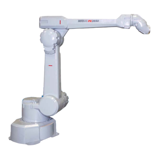
Motoman PX2850 Manual (611 pages)
XRC 2001 Controller Manipulator Manual
Brand:
Motoman
| Category:
Controller
| Size: 22 MB
Table of Contents
Table of Contents
3
Introduction
5
Safety
5
Px2850/Px2750 Instructions
5
Xrc Instructions (Supplement for Px -Series)
5
Xrc Instructions (Nas 2001)
5
Xrc Instructions-General (R2)
5
Px2850/Px2750 Elementary Diagrams
5
1 Safety
21
1 Safety
25
For Your Safety
25
Special Training
27
Motoman Manual List
27
Personnel Safety
28
Motoman Safety
30
Installation and Wiring Safety
30
Work Area Safety
34
Operation Safety
35
Notes for Moving and Transferring the MOTOMAN
38
Notes on MOTOMAN Disposal
39
2 Product Confirmation
41
Contents Confirmation
41
Order Number Confirmation
42
3 Installation
43
Handling Procedure
43
Using a Crane to Move the Controller
43
Using a Forklift to Move the Controller
44
Place of Installation
44
Location
45
Mounting the Controller
46
4 Connection
47
Notes on Cable Junctions
48
Power Supply
49
Three-Phase Power Supply
49
Leakage Breaker Installation
50
Noise Filter Installation
50
Primary Power Supply Switch Installation
51
Connection Methods
52
Connecting the Primary Power Supply
52
Connecting the Power Supply
55
Connecting the Programming pendant
57
5 Turning on the Power Supply
59
Turning on the Main Power Supply
59
Startup Diagnostics
59
When Startup Diagnostics Are Complete
60
Turning on the Servo Power
60
During Play Mode
60
During Teach Mode
61
Turning the Power off
62
Turning the Main Power off
62
Turning the Servo Power off (Emergency Stop)
62
6 Test of Program Operation
63
Movement of the Axes
65
Home Position Confirmation
67
Operating Procedure
69
8 Final Notes
71
1 Safety Precautions
78
1 Safety Precautions
81
2 Features
83
Methods of Protection
83
Teaching
83
3 Installation
85
Requirements
85
Installation Site
86
4 Handling and Installation
88
Preparation
88
Receiving and Handling
88
Installation of MOTOMAN
89
Installation of Manipulator
90
Safeguard Installation
90
Common Base
91
When the Manipulator and Mounting Fixture Are Installed on a
91
Location
92
Controller and Programming pendant
93
Safety Devices
93
5 Connection
94
Wiring
94
Grounding
94
Cable Connection
95
Connection to the Manipulator
95
Connection to the XRC
96
Metal Pipe Construction
97
Power Cable Construction Method Example
97
The Cables & Air-Tubing Connection(Procedure)
98
Internal Wiring
98
6 System Configuration
102
Manipulator
102
Robot Controller
105
Pneumatic Unit
105
O-Ring in the Wrist
107
7 Basic Specifications
108
Wrist Flange
110
System Application
112
8 Frequent Inspections
113
Daily Inspections
115
Dried Paint, Dust, and Dirt
115
Manipulator
115
Tubes
115
Visual Inspection
115
Air Leakage
116
Drained Water from Air Filter
116
Emergency Stop Button and Safety Plug
116
Noise and Vibration During Operation
116
Pneumatic Unit
116
Pressure
116
Safety Devices
116
Gun Tilt Switching
117
Limit Switch
117
Options
117
Photoelectric Intrusion Detecting Switch
117
Shear Pin
117
9 Maintenance and Inspection
118
Inspection Schedule
118
Maintenance for Manipulator
121
Grease Replenishment/Replacement
121
Gears
122
Harmonic Drive Speed Reducer
123
RV Speed Reducer
124
Cross Roller Bearing
126
Lubricating Oil Replacement for R- and B-Axes
127
Speed Reducers
127
Tightening Bolts
127
Air Sealings for Internal Air Pressure
129
Packing on the Motor Case
129
Wrist Speed Reducer and Bearing
129
Manipulator Base Box Cover Packings
131
Maintenance and Inspection of the Pneumatic Unit
132
Pressure Reducing Valve
132
Solenoid Valve
132
Inspection of Explosion-Proof Devices
132
Master Valve
132
Pressure Switch
132
Pressurized Explosion-Proof Barrier
133
Recommended Spare Parts
134
Parts List(PX2750-B30)
138
Parts List(PX2850-B10)
150
Parts List(PX2850-B20)
162
6 Yasnac Xrc Specification
197
YASNAC XRC Specification
199
6L6 Specification List
201
6L4 Function List
202
Programming pendant
203
Equipment Configuration
204
L6 Arrangement of Units and Circuit Boards
204
Configuration
204
L4 Cooling System of the Controller Interior
210
Description of Units and Circuit Boards
211
4L6 Power Supply Unit
212
4L4 Brake Release Unit
214
4L4L6 Operation Methods
214
CPU Rack
215
L6 CPU Rack Configuration
215
L4 Circuit Board in the CPU Rack
215
System Control Circuit Board (JANCD-XCP01)
215
Control Power Supply Unit (CPS-150F)
216
Wiring WAGO Connector
217
Wiring PHOENIX Connector
219
Direct in
222
Connected Jumper Leads before Shipment
223
Deadman Switch Signal Output
224
Connection to I/O External Power Supply
225
FORCE (Forced Reset)
226
FST (Full-Speed Test)
227
Hanger Switch (HSW)
228
1St Safety Speed and 2Nd Safety Speed
229
Safety Plug Input Signal
232
L4 General I/O Circuit Board (JARCR-XCI03)
232
Connection Wire with General I/O (CN10, 11, 12, 13)
233
Specific I/O Signal Related to Start and Stop
234
L_ Power on Unit (Jzrcr-Xsu)
236
4L_L6 Power on Circuit Board (JARCR-XCT01)
237
Connection of Shock Sensor
237
Method of Connecting External Axis Overrun Signal
238
Servo on Enable Input (ON_EN1 and 2)
239
Servopack
240
L6 SERVOPACK Configuration
240
Amplifier
249
Converter
249
L4 Description of each Unit
249
Servo Control Power Supply (JUSP-RCP01AA#)
249
Speed Monitor Board (Jancd-Xfc)
249
4La Playback Panel
250
Contact Output for Emergency Stop Button
250
4Lb General I/O Signal Assignment
251
4Lbl6 Arc Welding
251
4Lbl4 Handling
258
4Lbl] General Application
265
4Lbl^ Spot Welding
272
Arc Welding Application
281
Inspections
283
L6 Regular Inspections
283
L4 XRC Inspections
284
L4L6 Checking if the Doors Are Firmly Closed
284
L] Cooling Fan Inspections
285
L^ Emergency Stop Button Inspections
286
L_ Deadman Switch Inspections
286
L` Battery Inspections
287
La Power Supply Voltage Confirmation
287
Lb Open Phase Check
288
Replacing Parts
289
L6 Replacing XRC Parts
289
L6L6 Replacing the Disconnecting Switch
290
L6L4 Replacing Parts of Power Supply Unit
293
L4 YASNA XRC Parts List
294
L] Supplied Parts List
300
L^ Recommended Spare Parts
302
Setup • Diagnosis 15
326
Setup • Diagnosis
334
1 Outline of Setting and Diagnosis
336
2 Security System
338
Protection through Security Mode Settings
338
Security Mode
338
Modification of Security Mode
342
Changing a User ID
343
User ID
343
3 System Setup
346
Home Position Calibration
346
Calibrating Operation
348
Registering All Axes at on Time
348
Registering Individual Axes
349
Changing the Absolute Data
350
Clearing Absolute Data
351
Home Position of the Robot
352
Specified Point
353
Purpose of Position Check Operation
355
Specified Point Setting
356
Procedure after an Alarm
357
Setting the Controller Clock
358
Setting Play Speed
359
All Limits Releasing
361
Overrun / Shock Sensor Releasing
363
Interference Area
364
Cubic Interference Area
365
Setting Method
365
Setting Operation
366
Axis Interference Area
371
Setting Operation
371
Clearing Interference Area Data
374
Operation Origin Point Setting
375
Operation Origin Point Display
375
Registering/Changing the Operation Origin Point
375
Setting Operation Origin Point
375
What Is the Operation Origin Point
375
Output of the Operation Origin Point Signal
376
Returning to the Operation Origin Point
376
Tool Data Setting
377
Registering Tool Files
377
Number of Tool Files
377
Registering Coordinate Data
377
Registering Tool Pose
379
Setting the Tool Load Information
380
Tool Calibration
381
Teaching
381
Clearing Calibration Data
384
Checking the Tool Center Point
385
Automatic Measurement of the Tool Load and the Center of Gravity
386
Measurement of the Tool Load and the Center of Gravity
386
What Is the Automatic Measurement of the Tool Load and the Center of Gravity
386
3.10 User Coordinates Setting
390
User Coordinates
390
Definition of User Coordinates
390
User Coordinates File
390
Selecting User Coordinates File
391
Teaching User Coordinates
392
Clearing User Coordinates
393
ARM Control
394
ARM CONTROL Display
394
Robot Setup Condition
395
Setting
397
Tool Load Information Setting
398
How to Calculate Tool Load Information
399
Tool Load Information
399
Tool Load Information Registering
406
Shock Detection Function
409
Shock Detection Function Setting
409
Shock Detection Level Setting
409
Tool Load Information Setting
412
Instruction of Shock Detection Function
413
Reset Shock Detected
418
Alarm List
419
3.13 Instruction Level Setting
420
Setting Contents
420
Instruction Set
420
Learning Function
421
Setting Instruction Set Level Operation
421
3.14 Number Key Customize Function
422
Allocatable Functions
422
What Is the Number Key Customize Function
422
Key Allocation (EACH)
423
Key Allocation (SIM)
423
Allocating an Operation
424
Allocation Display
424
Instruction Allocation
425
Job Call Allocation
426
Display Allocation
427
Alternate Output Allocation
428
Momentary Output Allocation
428
Pulse Output Allocation
429
Analog Output Allocation
430
Group (4-Bit/8-Bit) Output Allocation
430
Allocation of I/O Control Instructions
431
Analog Incremental Output Allocation
431
Executing the Display Allocation
433
Executing the I/O Control Allocation
433
Executing the Instruction/Output Control Allocation
433
Executing the Job Call Allocation
433
Execution of Allocation
433
3.15 Changing the Output Status
434
3.16 Temporary Release of Soft Limits
436
3.17 File Initialize
438
Initialize Job File
438
Initialize Data File
439
Initialize Parameter File
440
Initializing I/O Data
441
Initializing System Data
442
4 Modification of System Configuration
444
Addition of I/O Modules
444
Addition of Base and Station Axis
446
Base Axis Setting
448
System Version
466
Input/Output Status
466
Universal Input
466
Universal Input Display
466
Universal Input Detailed Display
467
Universal Output
467
Universal Output Display
467
Modify the Output Status
468
Universal Output Detailed Display
468
Modify the Signal Name
469
Search the Signal Number
471
Specific Input
473
Specific Input Detailed Display
473
Specific Input Display
473
Specific Output
474
Specific Output Detailed Display
474
Specific Output Display
474
Rin Input
475
Rin Input Display
475
System Monitoring Time
476
System Monitoring Time Display
476
Individual Display of the System Monitoring Time
477
Clearing the System Monitoring Time
478
Alarm History
479
Alarm History Display
479
Clearing the Alarm History
479
I/O Message History
480
I/O Message History Display
480
Clearing the I/O Message History
481
Power On/Off Position Display
482
Regular Inspections
498
Xrc Inspections
499
Checking if the Doors Are Firmly Closed
499
Cooling Fan Inspections
500
Deadman Switch Inspections
501
Battery Inspections
502
Open Phase Check
504
Replacing Parts of the Cpu Rack
507
Replacing the Battery
507
Replacing the Jancd-Xcp01 Circuit Board
508
Replacing the Control Power Unit (Cps-150F)
509
Replacing the Servopack
510
Checking and Replacing Fuses
513
Replacing the Parts of I/O Power-On Unit
513
Recommended Spare Parts for SK45X
522
Alarm Message List
532
Advertisement
Advertisement
Related Products
Motoman PX2750
Motoman DX100
Motoman EA1400N
Motoman EA1900N
Motoman MotoPos-T1000
Motoman NX100
Motoman SK300X
Motoman XRC
Motoman XRC 2001
Motoman XRC Series
Motoman Categories
Controller
Robotics
Security System
More Motoman Manuals
Login
Sign In
OR
Sign in with Facebook
Sign in with Google
Upload manual
Upload from disk
Upload from URL