Table of Contents
Advertisement
Quick Links
XRC 2001 Controller
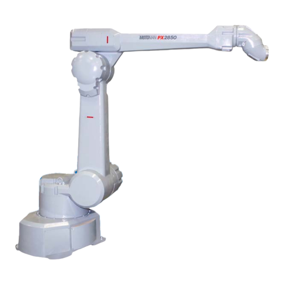
PX2850/PX2750
Manipulator Manual
Part Number 147197-1
March 15, 2002
MOTO MAN
805 Liberty Lane
West Carrollton, OH 45449
TEL: (937) 847-6200
FAX: (937) 847-6277
24-HOUR SERVICE HOTLINE: (937) 847-3200
The information contained within this document is the proprietary property of Motoman, Inc., and may
not be copied, reproduced or transmitted to other parties without the expressed written authorization of
Motoman, Inc.
©2002 by MOTO MAN
All Rights Reserved
Because we are constantly improving our products, we reserve the right to change specifications without notice.
MOTOMAN is a registered trademark of YASKAWA Electric Manufacturing.
Advertisement
Chapters
Table of Contents

Related Manuals for Motoman PX2850


Summary of Contents for Motoman PX2850
- Page 1 FAX: (937) 847-6277 24-HOUR SERVICE HOTLINE: (937) 847-3200 The information contained within this document is the proprietary property of Motoman, Inc., and may not be copied, reproduced or transmitted to other parties without the expressed written authorization of Motoman, Inc.
-
Page 3: Table Of Contents
INTRODUCTION .......................... 1-1 SAFETY ............................2-1 XRC SETUP ..........................3-1 PX2850/PX2750 INSTRUCTIONS ....................4-1 XRC INSTRUCTIONS (SUPPLEMENT FOR PX -SERIES)............. 5-1 XRC INSTRUCTIONS (NAS 2001) ....................6-1 XRC INSTRUCTIONS-GENERAL (R2) ..................7-1 PX2850/PX2750 ELEMENTARY DIAGRAMS ................8-1 MOTO MAN PX2850/PX2750 Manipulator Manual... - Page 4 NOTES PX2850/PX2750 Manipulator Manual MOTO MAN...
-
Page 5: Introduction
Furthermore, it provides main logic functions, servo control, program and constant data memory, and power distribution. Please read this manual thoroughly to familiarize yourself with the many aspects of the PX2850/PX2750 paint robot and XRC controller. About this Document... - Page 6 INTRODUCTION Customer Service Information If you are in need of technical assistance, contact the Motoman service staff at (937) 847-3200. Please have the following information ready before you call: • Robot Type (PX2850, etc.) • Application Type (assembly, handling, etc.) •...
- Page 7 We recommend that all personnel who intend to operate, program, repair, or use the robot system be trained in an approved Motoman training course and become familiar with the proper operation of the system. This safety section addresses the following: •...
- Page 8 NOTE: Information appearing in a NOTE caption provides additional information which is helpful in understanding the item being explained. PX2850/PX2750 Manipulator Manual MOTO MAN...
- Page 9 Safety fences and barriers • Light curtains • Door interlocks • Safety mats • Floor markings • Warning lights Check all safety equipment frequently for proper operation. Repair or replace any non-functioning safety equipment immediately. MOTO MAN PX2850/PX2750 Manipulator Manual...
- Page 10 Any modifications to the controller PLC can cause severe personal injury or death, as well as damage to the robot! Do not make any modifications to the PLC. Making any changes without the written permission of Motoman will VOID YOUR WARRANTY! •...
- Page 11 All modifications made to the controller will change the way the robot operates and can cause severe personal injury or death, as well as damage the robot. This includes controller parameters, and I/O (Input and Output) modifications. Check and test all changes at slow speed. MOTO MAN PX2850/PX2750 Manipulator Manual...
- Page 12 Check and test all changes at slow speed. • Improper connections can damage the robot. All connections must be made within the standard voltage and current ratings of the robot I/O (Inputs and Outputs). PX2850/PX2750 Manipulator Manual MOTO MAN...
- Page 13 MOTOMAN SETUP MANUAL Upon receipt of the product and prior to initial operation, read these instructions thoroughly, and retain for future reference. MOTOMAN INSTRUCTIONS MOTOMAN SETUP MANUAL MOTOMAN- ooo MANIPULATOR INSTRUCTION MANUAL YASNAC XRC INSTRUCTION MANUAL YASNAC XRC OPERATOR’S MANUAL YASNAC XRC OPERATOR’S MANUAL FOR BEGINNERS...
- Page 14 • This manual explains the various components of the YASNAC XRC sys- tem and general operations. Read this manual carefully and be sure to understand its contents before handling the YASNAC XRC. • General items related to safety are listed in Section 1: Safety of the Setup Manual.
- Page 15 NOTES FOR SAFE OPERATION Read this manual carefully before installation, operation, maintenance, or inspection of the YASNAC XRC. In this manual, the Notes for Safe Operation are classified as “WARNING,” “CAUTION,” “MAN- DATORY,” or “PROHIBITED.” Indicates a potentially hazardous situation which, if not avoided, could result in death or serious injury to personnel.
- Page 16 • Before operating the manipulator, check that the servo power is turned off when the emergency stop buttons on the playback panel or program- ming pendant are pressed. When the servo power is turned off, the SERVO ON READY lamp on the playback panel and the SERVO ON LED on the programming pendant are turned off.
- Page 17 • Read and understand the Explanation of the Alarm Display in the Setup Manual before operating the manipulator. Definition of Terms Used Often in This Manual The MOTOMAN manipulator is the YASKAWA industrial robot product. The manipulator usually consists of the controller, the playback panel, the programming pen- dant, and supply cables.
- Page 18 Descriptions of the programming pendant and playback panel keys, buttons, and displays are shown as follows: Equipment Manual Designation Programming Character Keys The keys which have characters printed on them are Pendant denoted with [ ], e.g., [ENTER]. Symbol Keys The keys which have a symbol printed on them are not denoted with [ ] but depicted with a small picture.
- Page 19 Explanation of warning labels The following warning labels are attached to the manipulator and XRC. Fully comply with the precautions on the warning labels. • The label described below is attached to the manipulator. Observe the precautions on the warning labels. Failure to observe this caution may result in injury or damage to equipment.
- Page 20 viii...
- Page 21 1.5.3 Operation Safety ........1-11 1.6 Notes for Moving and Transferring the MOTOMAN .
- Page 22 Turning on the Power Supply 5.1 Turning on the Main Power Supply ......5-1 5.1.1 Startup Diagnostics ........5-1 5.1.2 When Startup Diagnostics are Complete .
- Page 23 This manual is arranged as follows: Chapter 1 includes general notes for safe and proper operation of the MOTOMAN. Chapter 2 explains how to receive the manipulator and its support equipment. Chapter 3 explains XRC installation, location, and setup.
-
Page 25: Safety
1.1 For Your Safety 1 Safety For Your Safety Robots generally have requirements which are different from other manufacturing equipment, such as larger working areas, high-speed operation, rapid arm movements, etc., which can pose safety hazards. Read and understand the instruction manuals and related documents, and observe all pre- cautions in order to avoid the risk of injury to personnel and damage to equipment. - Page 26 1.1 For Your Safety • Teaching maintenance of the robot must conform to: -Industrial Safety and Health Law -Enforcement Order of Industrial Safety and Health Law -Ordinance of Industrial Safety and Health Law Other related laws are: -Occupational Safety and Health Act in USA -Factory Act (Gewerbeordnung) in Germany -Health and Safety at Work, etc.
-
Page 27: Special Training
• For more information on training, inquire at the nearest YASKAWA branch office. The telephone numbers are listed on the back cover of this manual. Motoman Manual List • It is important to have and be familiar with all manuals concerning the MOTOMAN. -
Page 28: Personnel Safety
"Safety First" minded, to ensure the safety of all personnel. • Avoid any dangerous actions in the area where the MOTOMAN is installed. There is a danger of injury if there is contact with the manipulator or peripheral equip- ment. - Page 29 1.4 Personnel Safety • Never forcibly move the manipulator axes. Failure to observe this caution may result in injury or equipment damage. • Never lean on XRC or other controllers, and avoid inadvertently pushing buttons. Failure to observe this caution may result in injury or damage by unexpected movement of the manipulator.
-
Page 30: Motoman Safety
1.5 Motoman Safety Motoman Safety 1.5.1 Installation and Wiring Safety Refer to the MOTOMAN-ooo Instructions manual and XRC Instructions for details on instal- lation and wiring. In planning installation, adapt an easy to observe arrangement to ensure safety. Take safety into consideration when planning the installation. - Page 31 Failure to observe this precaution may result in injury or equipment damage. MOTOMAN should be lifted with a crane using wire rope threaded through the shipping bolts and jigs and the body should be lifted in an upright posture as described in the manipulator instruction manual.
- Page 32 Failure to observe this precaution may result in injury or damage to equipment resulting from contact with the manipulator. • Install the manipulator using bolts of the size and type specified for each MOTOMAN in the MOTOMAN INSTRUCTION MANUAL. Failure to observe this caution may result in injury or damage to equipment.
- Page 33 1.5 Motoman Safety • Secure the position of the XRC after setting up. Attach the XRC to the floor or rack, etc., using the screw holes on the bottom of the XRC. Failure to observe this caution could lead to injury or equipment damage if the XRC should shift or fall.
-
Page 34: Work Area Safety
1.5 Motoman Safety 1.5.2 Work Area Safety Carelessness contributes to serious accidents in the work area. To ensure safety, enforce the following precautions: • Install an enclosure around the manipulator to prevent any accidental contact with the manipulator while the power is on. -
Page 35: Operation Safety
1.5 Motoman Safety 1.5.3 Operation Safety • When attaching a tool such as the welding torch to the manipulator, be sure the power supply of the XRC and the tool is off, lock the switch, and display a warning sign. - Page 36 1.5 Motoman Safety • Before operating the manipulator, confirm that the emergency stop cir- cuit is functioning by pressing the emergency stop button on the play- back panel and programming pendant, and confirm that the servo lamp is turned off.
- Page 37 1.5 Motoman Safety • Inspect all equipment before turning on power to the controller. Correct problems before operating. -Check for problems in manipulator motion -Check for damage to insulation and sheathing of cables. • Always return the programming pendant to the hook on the front of the controller after use.
-
Page 38: Notes For Moving And Transferring The Motoman
Contact your YASKAWA representative if you require new warning labels. • When the MOTOMAN is transferred, it is recommended to check with Yaskawa Engineering Co. which is listed on back cover of this manual. -
Page 39: Notes On Motoman Disposal
1.7 Notes on MOTOMAN Disposal Notes on MOTOMAN Disposal • When disposing of the MOTOMAN, follow the applicable national/local laws and regulations. • Anchor the manipulator well, even when temporarily storing it before disposal. Failure to observe this precaution may result in injury due to the manipulator falling down. - Page 40 1.7 Notes on MOTOMAN Disposal 1-16...
-
Page 41: Product Confirmation
2.1 Contents Confirmation 2 Product Confirmation Contents Confirmation Confirm the contents of the delivery when the product arrives. Standard delivery includes the following five items (Information for the content of optional goods is given separately): • Manipulator • XRC • Programming Pendant •... -
Page 42: Order Number Confirmation
2.2 Order Number Confirmation Order Number Confirmation Confirm that the order number pasted on the manipulator and XRC match. The order number plates are affixed to the figure below. Example... -
Page 43: Installation
3.1 Handling Procedure 3 Installation Handling Procedure • Crane, sling, and forklift operations must be performed only by autho- rized personnel. Failure to observe this caution may result in injury or damage. • Avoid jarring, dropping, or hitting the controller during handling. Excessive vibration or impacting the XRC may adversely affect the performance of the XRC. -
Page 44: Using A Forklift To Move The Controller
3.2 Place of Installation 3.1.2 Using a Forklift to Move the Controller Observe the following precautions when using a forklift to handle the controller: • Confirm that there is a safe work environment and that the XRC can be transported safely to the installation site. -
Page 45: Location
3.3 Location Location • Install the XRC outside of the working envelope of the manipulator (outside of the enclo- sure) ENCLOSURE DOOR 1000 mm or more 1000 mm or more 1000 mm or more WORKING ENVELOPE OF MANIPULATOR MAXIMUM WORKING ENVELOPE OF MANIPULATOR INCLUDING TOOL OR WORKPIECE END 1000 mm or more... -
Page 46: Mounting The Controller
3.4 Mounting the Controller Mounting the Controller Attach the controller to the floor using user-supplied brackets made according to the specifica- tions shown below. External Dimensions (mm) Attaching the XRC (mm) Refer to the Instruction Manual for information on installation of the manipulator. -
Page 47: Connection
4 Connection • The system must be grounded. Failure to ground equipment may result in injury from fire or electric shock. • Before grounding the system, turn off the power supply and lock the main power switch. Failure to observe this caution may result in injury and electric shock. •... -
Page 48: Notes On Cable Junctions
4.1 Notes on Cable Junctions • Wiring must be performed only by authorized personnel. Incorrect wiring may cause fire and electric shock. • Perform wiring in accordance with the rated capacity as specified in the Instructions. Incorrect wiring may cause fire or mechanical breakdown. •... -
Page 49: Power Supply
4.2 Power Supply XRC Cable Junction Diagram Power Supply 4.2.1 Three-Phase Power Supply The three-phase power supply consists of AC200/220V(+10/-15%) and 50/60Hz(+2Hz/-2Hz). The power failure processing circuit operates when there is a temporary power frequency black out or drop in voltage, and the servo power turns off. Connect the power supply to a stable power source that is not prone to power fluctuations. -
Page 50: Noise Filter Installation
4.2 Power Supply 4.2.2 Noise Filter Installation Insert the three-phase noise filter if you hear noise coming from the power source. Seal up each cable opening so that dust does not enter. Connection of Three-Phase Noise Filter 4.2.3 Leakage Breaker Installation When connecting the leakage breaker to the controller power supply wiring, use a leakage breaker which can handle high frequencies. -
Page 51: Primary Power Supply Switch Installation
4.2 Power Supply 4.2.4 Primary Power Supply Switch Installation Install the primary power supply switch as shown. Installation of the Primary Power Supply Switch Cable Sizes and Switch Capacities Voltage Switch Cable size (size of terminal) source Manipulator capacity capacity (In case of Cabtyre cable (four wicks)) mm (kVA) SV3X... -
Page 52: Connection Methods
4.3 Connection Methods Connection Methods A connection diagram for the manipulator, controller power cable, primary power cable and programming pendant is shown below. 4.3.1 Connecting the Primary Power Supply Open the front door of the XRC. (1) Insert the door handle in the door lock on the front of XRC (two places), and rotate it 90 degrees clockwise. - Page 53 4.3 Connection Methods Rotating the main switch to the OPEN RESET position. 2. Confirm that the main power supply is OFF. 3. Make a hole in the plate and run the primary power supply cable through it. It is located on the top or on the left side of the XRC.
- Page 54 4.3 Connection Methods (3) Connect a ground wire to reduce noise and prevent current leakage. 1) Connect the ground wire to the ground terminal (screw) of the switch which is on the upper left side of XRC. Ground wire Crimped terminal Connection of the Ground Wire 2) Perform grounding in accordance with all relevant local and national electrical codes.
-
Page 55: Connecting The Power Supply
4.3 Connection Methods (4) Install the cover. Install the Switch Cover 4.3.2 Connecting the Power Supply 1. Remove the cover from the left side of the controller cabinet. Detaching the Cable Hole Cover... - Page 56 4.3 Connection Methods 2. Remove the package, and take out the cable. Once you have run the cables through the cable holes on each side of XRC, tighten the screws. Tightening the Screws for the Cable Cables Passed Through the Holes in the Side of the XRC For more information on connecting the power cables, please refer to the Instruction Man- ual which corresponds to the particular XRC model.
-
Page 57: Connecting The Programming Pendant
4.3 Connection Methods 4.3.3 Connecting the Programming Pendant Connect the programming pendant cable to the connector on the left side of the controller cabinet. Connecting the Programming Pendant The manipulator, XRC, and the programming pendant connections are now complete. 4-11... - Page 58 4.3 Connection Methods 4-12...
-
Page 59: Turning On The Power Supply
5.1 Turning on the Main Power Supply 5 Turning on the Power Supply • Confirm that nobody is present in the working envelope of the manipula- tor when turning on XRC power supply. Failure to observe this caution could result in injury caused by accidental contact with the manipulator. -
Page 60: When Startup Diagnostics Are Complete
5.2 Turning on the Servo Power 5.1.2 When Startup Diagnostics are Complete When the power is turned off, the XRC saves all condition data, including: • Mode of operation • Cycle • Called job (active job if the XRC is in the play mode; edit job if the XRC is in the teach mode) and the cursor position in the job. -
Page 61: During Teach Mode
5.2 Turning on the Servo Power 5.2.2 During Teach Mode 1. Press [SERVO ON READY] on the playback panel to turn on the servo power supply. The button will light when the servo power is turned on. 2. Press [TEACH LOCK] to enter the teach mode. 3. -
Page 62: Turning The Power Off
5.3 Turning the Power Off Turning the Power Off 5.3.1 Turning the Servo Power Off (Emergency Stop) The manipulator cannot be operated when the emergency stop button is pressed and the servo power supply is turned off. Turning the Servo Power Off •... -
Page 63: Test Of Program Operation
6 Test of Program Operation • Press the emergency stop button on the playback panel and the pro- gramming pendant before operating the manipulator. Confirm that the servo on lamp is turned off. Injury or damage to machinery may result if the manipulator cannot be stopped in case of an emergency. - Page 64 • Inspect the system before teaching jobs. If problems are found, correct them before resuming operation. Specifically check for: -Problems in manipulator motion -Damage to cables • Always return the programming pendant to its specified position after use. The programming pendant can be damaged if it is left in the manipulator work area or on the floor.
-
Page 65: Movement Of The Axes
6.1 Movement of the Axes Movement of the Axes Move each axis of the manipulator by pressing the axis keys on the programming pendant. This figure illustrates each axis of motion in the joint coordinate system. Be sure to remove all items from the area before moving the manipulator. Refer to the Instruction Manual for the appropriate position of the fixture. - Page 66 6.1 Movement of the Axes...
-
Page 67: Home Position Confirmation
7 Home Position Confirmation • Press each emergency stop button on the playback panel and the pro- gramming pendant before operating the manipulator. Be sure the servo on lamp is turned off. There is a danger of injury and equipment damage if the manipulator cannot be stopped in the event of an emergency. - Page 68 • Perform the following inspection procedures before starting to teach. If problems are found, repair them immediately and be sure all necessary processing has been performed: -Check for problems in manipulator movement. -Check for damage to insulation and sheathing of external wires. •...
-
Page 69: Operating Procedure
7.1 Home Position Confirmation Home Position Confirmation It is necessary to register the home position (each axis has a position of 0 pulse) correctly so that the manipulator will work accurately. The home position for the UP6 is shown. Other manipulator models have different positions. Always consult the documentation for the correct manipulator model. - Page 70 7.1 Home Position Confirmation The angle of the central line of The angle of the L-axis perpendicular to the B-axis against the central the ground. line of the U-axis is 90 degrees. B-AXIS R-AXIS T-AXIS U-AXIS (opposite side) The angle of the U-axis against the horizon is 0 degrees.
-
Page 71: Final Notes
Composed of several sections, each corresponding to operation of the system. Work involving setting and diagnosis of the controller, alarm explanations, setting of the home position, etc. • MOTOMAN-***** Instruction manual Covers manipulator topics • INFORM Manual Covers the INFORM robot programming language •... - Page 74 BEIJING YASKAWA BEIKE AUTOMATION ENGINEERING CO.,LTD. 30 Xue Yuan Road, Haidian, B eijing P.R. China Post Code: 100083 Phone 86-10-6233-2782 Fax 86-10-6232-1536 SHOUGANG MOTOMAN ROBOT CO., LTD. 7,Yongchang-North Street, Beijing Economic Technological Investment & Development Area, Beijing 100076, P.R. China Phone 86-10-6788-0551...
- Page 75 YR-PX2850-B20 YR-PX2750-B30 Upon receipt of the product and prior to initial operation, read these instructions thoroughly, and retain for future reference. MOTOMAN INSTRUCTIONS MOTOMAN SETUP MANUAL MOTOMAN- INSTRUCTIONS YASNAC XRC INSTRUCTIONS YASNAC XRC OPERATOR’S MANUAL YASNAC XRC OPERATOR’S MANUAL for BEGINNERS The YASNAC XRC operator’s manuals above correspond to specific usage.
- Page 76 • This manual describes the specifications, precautions for operation and required items for maintenance or inspections, for proper application of the MOTOMAN-PX2850/-PX2750. Read this manual carefully and be sure to understand its contents before handling the MOTOMAN. • General items related to safety are listed in Section 1: Safety of the Setup Manual.
- Page 77 “CAUTION” and “WARNING”. Definition of Terms Used Often in This Manual The MOTOMAN manipulator is the YASKAWA industrial robot product. The manipulator usually consists of the controller, the playback panel, the programming pen- dant, and supply cables.
- Page 78 ......4-1 4.3 Installation of MOTOMAN ......4-2 4.3.1 Safeguard Installation .
- Page 79 HW0480633 System Configuration 6.1 Manipulator .........6-1 6.2 Robot Controller .
- Page 80 ......11-1 11.2 Parts List(PX2850-B10) ......11-13 11.3 Parts List(PX2850-B20)
-
Page 81: Safety Precautions
Appoint a person to be in charge of teaching, maintenance and inspections and provide training or lectures on safety and the actions to be taken in case of an emergency. WARNING Install the MOTOMAN-PX2850/-PX2750 in a location that meets the requirements of Area Classification ’Division I’ prescrived in FM Approval Standard. - Page 82 Use the brake release function only when absolutely necessary. PROHIBITED Any modification of the MOTOMAN-PX2850, and the following is strictly prohibited: 1. Explosion-proof devices and system installation 2. Safeguards and the safety devices mounted on these safeguards 3. Emergency stop button, and other safety devices 4.
-
Page 83: Features
Methods of Protection The MOTOMAN-PX2850/-PX2750 are evaluated as Type X Purged for use in ClassI, Division 1, Groups A, B, C and D indoor hazardous (classified), and appear in the Factory Mutual (FM) Research Approval Guide.They have the construction of protection as follows: Metod of Protection;... - Page 84 HW0480633 2.2 Teaching CAUTION Be sure to save the backup data for the controller, such as the data for jobs and con- stants, on a PC card. If not, the necessary data for the manipulator may be lost if an inter- nal memory fault occurs in the controller.
-
Page 85: Installation
HW0480633 3.1 Requirements 3 Installation Requirements Prepare the power supply, the air supply, and the grounding according to the following specifi- cations. Table. 1 Specifications Item Specifications Remarks Power supply 3-phase 200/220 VAC ( ± 10 % ) 50/60 Hz ( ±2 Hz) 5 kVA (at peak) Air supply Required pressure: 0.35 MPa to 0.65... -
Page 86: Installation Site
HW0480633 3.2 Installation Site Installation Site This section describes the conditions of the installation site for the robot system. Only devices that are approved as explosion-proof can be installed in hazardous locations. Refer to the local regulations and safety codes for the definition of a hazardous location. Install the con- troller and control panels in a location free from water drops, dust, and dirt. - Page 87 HW0480633 3.2 Installation Site WARNING Devices that are not explosion-proof must not be installed in hazardous locations. Fail- ureto observe this warning may result in a fire.
-
Page 88: Handling And Installation
4.1 Preparation 4 Handling and Installation Read “MOTOMAN Setup Manual”thoroughly before handling and installing the MOTOMAN system , and then carry out the operation safely observing the following precautions. 1) Signs indicating prohibitions such as, “The lighting of fires is prohibited”... -
Page 89: Installation Of Motoman
HW0480633 4.3 Installation of MOTOMAN Installation of MOTOMAN WARNING • Install safeguards. Failure to observe this warning may result in injury or damage. • Install the manipulator in a location where the fully extended arm and tool will not reach the wall, safeguards, and the XRC. -
Page 90: Safeguard Installation
Mounting Fixture are Installed on a Common Base " and " 4.3.4 When the Manipulator is Mounted Directly on the Floor ". Table. 3 Maximum Repulsion Forces of the the PX2850/PX2750 Horizontal rotating maximum torque 16000N • m (S-axis moving direction) (1600kgf•... -
Page 91: When The Manipulator And Mounting Fixture Are Installed On A
HW0480633 4.3 Installation of MOTOMAN 4.3.3 When the Manipulator and Mounting Fixture are Installed on a Common Base The common installation base should be rugged and durable to prevent shifting of the manip- ulator or the mounting fixture. It is recommended that the thickness of the common installa- tion base is 40 mm or more, the anchor bolt is M16 or more. -
Page 92: Location
HW0480633 4.3 Installation of MOTOMAN *365 *265 Manipulator base Anchor bolt M16 (4 bolts) Concrete floor 150mm or more Fig. 3 Direct Mounting on the Floor 4.3.5 Location Install the manipulator in a location that has the following environmental conditions: •... -
Page 93: Controller And Programming Pendant
HW0480633 4.3 Installation of MOTOMAN 4.3.6 Controller and Programming Pendant • The controller and the programming pendant are not explosion-proof ( the explosion- proof programming pendant is available as an option). Never install the controller and the programming pendant that are not explosion-proof in a hazardous location. -
Page 94: Connection
HW0480633 5.1 Wiring 5 Connection Wiring WARNING • Ground resistance must be 100 Ω or less. (Non I.S. GND) 10 Ω or less. (I.S. GND) Failure to observe this warning may result in fire or electric shock. • Before wiring, make sure to turn the primary power supply OFF, and put up a warning sign. (ex. -
Page 95: Cable Connection
HW0480633 5.2 Cable Connection The grounding methods differ depending on the system application. Refer to the connection instructions that are provided separately. Remove the Cover 5.5mm or more (Prepare by the customer) less than 0.1Ω Fig. 4 Grounding Method Cable Connection 5.2.1 Connection to the Manipulator Before connecting the cables to the manipulator, verify the connectors named 1BC-1, -2, -3, -... -
Page 96: Connection To The Xrc
HW0480633 5.2 Cable Connection 5.2.2 Connection to the XRC Remove the cover on the XRC side. Pass the signal cable for detection (1BC) and power cable (2BC) through the opening for the cables, and then fasten bolts on the opening. Connect the 1BC cable to the boards. -
Page 97: Power Cable Construction Method Example
HW0480633 5.2 Cable Connection 5.2.3 Power Cable Construction Method Example The construction example is shown as follows. Metal Pipe Construction Non Hazardous Location Hazardous Location (Outside of Booth) (Inside of Booth) max:30m Rigid Steel Conduits Sealing Compound Chico A Sealing Fitting EYS41 Cable Control... -
Page 98: The Cables & Air-Tubing Connection(Procedure)
HW0480633 5.3 Internal Wiring 5.2.4 The Cables & Air-tubing Connection(procedure) Cables and tubes necessary for construction are tables below. The customer needs to prepare the power supply cable, the grounding cable, the cables for the optional equipment, and the air tube. Use. - Page 101 Fig.8(c) Intrinsically Safe Circuit Diagram...
-
Page 102: System Configuration
" Fig. 10 Dimensions and Working Envelopes " shows the dimensions and the working enve- lopes of the PX2850/PX2750.The manipulator is driven by the servo motor in vertically articu- lated operation mode with 6 degrees of freedom on the manipulator base. The motion of the... - Page 103 HW0480633 6.1 Manipulator Hazardous location Non-hazardous location Conveyor speed detector (Option) Program Conveyor Switch selector (Option) (Option) Air tube (2) AIR SUP. Manipulator (0.35~0.65MPa) Pneumatic (3.5~6.5kg/cm unit Programming pendant (PP) Robot Controller POWER SUP. (3-phase 200/220VAC 50/60Hz) Workpiece supplier (Option) less than 0.1Ω...
- Page 104 Working envelope of wrist rotation center point P rotation center point P 1338 1316 2275 2335 2829 2834 PX2850-B10 PX2850-B20 18 dia. mounting hole (4 holes) Working envelope of wrist rotation center point P Point P Manipulator base ±260° ±260° ±270°...
-
Page 105: Robot Controller
HW0480633 6.2 Robot Controller Robot Controller The robot controller has a built-in microcomputer that controls all motion of the robot by saving motion signals when teaching and sending these signals to the manipulator. The power unit that supplies power to the manipulator is also built into the robot controller. WARNING The power supply of the robot controller is 200/220 VAC. - Page 106 HW0480633 6.3 Pneumatic Unit P1(Setting Pressure) Pressure reducing valve for setting 0.02 0.04MPa(0.20 0.40 kgf/cm Supply Pressure P2(Purge Air Pressure) 0.35~0.65MPa Pressure reducing valve (3.5~6.5 kgf/cm for Purge Air 0.3 0.45MPa Manipulator 3.0 4.5 kgf/cm Air in Filter Pressure reducing valve for setting Manipulator PO(Pressure)
-
Page 107: O-Ring In The Wrist
HW0480633 6.4 O-ring in the Wrist O-ring in the Wrist Periodically replace the O-rings in the wrist. Contact your Yaskawa representative to replace the rings. When the wrist is cleaned 2 or 3 times a week with the recovered thinner, the O- rings may become deformed, which causes malfunctions. -
Page 108: Basic Specifications
HW0480633 7.1 Basic Specifications 7 Basic Specifications Basic Specifications Table. 4 PX2850 Basic Specifications MOTOMAN- MOTOMAN- Item Type PX2850-B10 PX2850-B20 Operation Mode Vertically Articulated Degree of Freedom Payload 10 kg ± 0.5 mm Repetitive Positioning Accuracy S-axis (turning) ± 150°... - Page 109 HW0480633 7.1 Basic Specifications Table. 5 PX2750 Basic Specifications MOTOMAN- Item Type PX2750-B30 Operation Mode Vertically Articulated Degree of Freedom Payload 10 kg ± 0.5 mm Repetitive Positioning Accuracy S-axis (turning) ± 150° L-axis (lower arm) + 90°, - 40°...
-
Page 110: Wrist Flange
7.2 Wrist Flange Wrist Flange The wrist flange dimensions are shown in " Fig. 13 Wrist Flange (for PX2850-B10) " to " Fig. 15 Wrist Flange (for PX2750-B30) ". Fitting depth of inside fittings must be 3mm or less (PX2850-B10) and 6mm or less (PX2850-B20, PX2750-B30). - Page 111 HW0480633 7.2 Wrist Flange O ring (attached to the manipulator) Tapped hole 8-M6 X 1 (depth: 9 mm) Fig. 15 Wrist Flange (for PX2750-B30)
-
Page 112: System Application
HW0480633 7.3 System Application System Application The device required for the system application can be mounted on the horizontal arm. Observe the following restrictions. • Maximum allowable load: 20 kg • Mounting position: Refer to " Fig. 16 Device Mounting Position ". Allowable load : 20 kg or less 700mm or less Fig. -
Page 113: Frequent Inspections
HW0480688 8.1 Frequent Inspections 8 Frequent Inspections Frequent Inspections The painting robot is a precision device using advanced technology. It is important to fre- quently inspect the robot and remove any dried paint. Conduct the daily and weekly inspections listed in " Table. 6 Frequent Inspections " to ensure the long life of the robot and its performance. - Page 114 HW0480688 8.1 Frequent Inspections Table. 6 Frequent Inspections Week Items to be Inspected Inspection Daily Remarks Operation of emer- 1. The manipulator CAUTION gency stop button stops immediately Inspect the robot while and safety plug. when the it is in its standby posi- Dried paint emergency stop tion and not in motion.
-
Page 115: Daily Inspections
HW0480688 8.2 Daily Inspections Daily Inspections Inspect the robot daily to ensure its high performance and early detection of any abnormali- ties. 8.2.1 Manipulator Visual inspection Before turning ON the power to the manipulator, check if any abnormality can be found on the manipulator. -
Page 116: Air Leakage
HW0480688 8.2 Daily Inspections Air leakage Check for excessive air leakage from the tubes, the couplings, and the joint fittings of the motor on each axis when the air is supllied in the manipulator to form the explosion-proof bar- rier. The actual amount of air leakage is not important if a fault in the internal air pressure does not occur. -
Page 117: Photoelectric Intrusion Detecting Switch
HW0480688 8.2 Daily Inspections Photoelectric intrusion detecting switch Make sure that the photoelectric intrusion detecting switch operates correctly. Remove any dried paint on the light beam receiving section on the switch. When the air is purging, check the air for purging. Limit switch Make sure that the limit switches for positioning workpieces, starting the robot, and return the robot to home operate correctly. -
Page 118: Maintenance And Inspection
HW0480633 9.1 Inspection Schedule 9 Maintenance and Inspection WARNING • Before maintenance or inspection, be sure to turn the main power sup- ply OFF, and put up a warning sign such as “DO NOT TURN THE POWER ON”. Failure to observe this warning may result in electric shock or injury. CAUTION •... - Page 119 Tighten the bolts that loosed from Tightening of vibration and bolts an exces- sively swing- ing load. Replace- Hose ment of (PX2850-B10) hose (3000H) Inspection of Replace if any O-ring wrist abnormality is found. Contact your Presence Yaskawa represen- check of tative.
- Page 120 HW0480633 9.1 Inspection Schedule Table. 7 Inspection Schedule Inspection Schedule charge Maintenance Item Operation Inspection Specified Service 1000H 6000H 12000H Licen 24000H 36000H person- com- cycle cycle cycle pany Replace the pneumatic unit filter. Check the operation of Replacement the solenoide of pneumatic valve.
-
Page 121: Maintenance For Manipulator
3) RV speed reducers for the S- and L-axes 4) Cross roller bearing for the S-axis U-arm Wrist Motors for R-, B- and T-axes R-, B- and T-axes speed reducers (PX2850-B10) R- and B-axes speed reducers (PX2850-B20,PX2750-B30) U-axis motor and speed reducer T-axis speed reducer (PX2850-B20,PX2750-B30) -
Page 122: Gears
Remove the cover and the plug. Inject Alvania EP grease 2 by using a grease gun to the gear teeth. See " Fig. 18 Injecting Grease at wrist and End of U-arm (for PX2850-B10) " to " Fig. 20 IInjecting Grease at Wrist and End of U-arm (for PX2750-B30) ". -
Page 123: Harmonic Drive Speed Reducer
Fig. 20 IInjecting Grease at Wrist and End of U-arm (for PX2750-B30) Harmonic Drive speed reducer For the U-Axis Harmonic Drive speed reducer, the customer is responsible for replenishing the grease. But for the T-Axis speed reducer (PX2850-B20, PX2750-B30), contact your Yaskawa representative. Grease Replenishment Refer to "... -
Page 124: Rv Speed Reducer
HW0480633 9.2 Maintenance for Manipulator Uo: Air flow (with hexagon socket head plug PT1/8) U-axis speed reducer Ui: Grease inlet (with hexagon socket head plug PT1/8) Fig. 21 U-axis Harmonic Drive Speed Reducer RV speed reducer Grease Replenishment Refer to " Fig. 22 S-axis RV Speed Reducer " and " Fig. 23 L-axis RV Speed Reducer ". 1. - Page 125 HW0480633 9.2 Maintenance for Manipulator Grease Replacement Refer to " Fig. 22 S-axis RV Speed Reducer " and " Fig. 23 L-axis RV Speed Reducer ". 1. Remove the plug in the So (Lo) grease exhaust port. Remove the cover on the L-axis motor side.
-
Page 126: Cross Roller Bearing
HW0480633 9.2 Maintenance for Manipulator Lo: Grease exhaust port (with hexagon socket head plug PT1/8) L-axis speed reducer Cover on L-axis moter side Li: Grease inlet (Note: Remove the hexagon socket head plug and install a G nipple A-PT1/8 before injecting grease.) Fig. -
Page 127: Lubricating Oil Replacement For R- And B-Axes
Manipulator base box fixing bolts 4-M16 Fig. 25 Manipulator Base Box and Bearing Fixing Bolts Hexagon socket head bolt 6-M6 Hexagon socket head bolt 6-M6 Tightening torque 11.5N•m Tightening torque 11.5N•m (117kgf•cm) (117kgf•cm) U-arm Wrist Fig. 26 Wrist Fixing Bolts (for PX2850-B10) 9-10... - Page 128 Hexagon socket head bolt 6-M6 Hexagon socket head bolt 5-M6 Tightening torque 11.5N•m Tightening torque 11.5N•m (117kgf•cm) (117kgf•cm) Fig. 27 Wrist Fixing Bolts (for PX2850-B20) Hexagon socket head bolt 5-M6 Hexagon socket head bolt 6-M6 Tightening torque 11.5N•m Tightening torque 11.5N•m (117kg•cm) (117kg•cm)
-
Page 129: Wrist Speed Reducer And Bearing
HW0480633 9.2 Maintenance for Manipulator Terminal box fixing screws Fig. 29 Terminal Box in Manipulator Base Box 9.2.4 Wrist Speed Reducer and Bearing Check if the three wrist axes move smoothly or not. If the wrist does not move smoothly, con- tact your Yaskawa representative. - Page 130 HW0480633 9.2 Maintenance for Manipulator Motor case Packing Packing Fig. 30 S- and L-axes Motor Packings Packing Motor case U-axis motor Cover Packing Fig. 31 U-axis Motor Packing (b) R-, B-, and T-axes The packing is provided on the joint fetting between the back of the U-arm and the motor case.
-
Page 131: Manipulator Base Box Cover Packings
HW0480633 9.2 Maintenance for Manipulator R-, B- and T-axes motors U-arm Packing Motor case Fig. 32 R-, B-, and T-axes Motor Packings Manipulator Base Box Cover Packings Remove the two covers on the back side of the manipulator base box, and check the rubber packing.Refer to "... -
Page 132: Maintenance And Inspection Of The Pneumatic Unit
HW0480633 9.3 Maintenance and Inspection of the Pneumatic Unit Maintenance and Inspection of the Pneumatic Unit 9.3.1 Solenoid Valve Check if the air purge starts a few seconds after turning ON the power to the XRC and if it ends approximately 11 minites later. 9.3.2 Pressure Reducing Valve Measure the air pressure for the pneumatic unit with a pressure gauge. -
Page 133: Pressurized Explosion-Proof Barrier
HW0480633 9.4 Inspection of Explosion-proof Devices 9.4.3 Pressurized Explosion-proof Barrier While the air is being supplied from the pneumatic unit, check if the air purge starts a few sec- onds after the power to the XRC is turned ON and if it ends approximately 11 minutes later. Also, check the following: (a) The alarm “AIR PRESSURE ERROR”... -
Page 134: Recommended Spare Parts
It is recommended that the following parts and components be kept in stock as spare parts for the MOTOMAN-PX2850/-PX2750. The spare parts list is shown below. Product performance can not be guaranteed when using spare parts from any company other than Yaskawa. - Page 135 HW0480633 Table. 8 Spare Parts for PX2850-B10 Yaskawa Electric T-axis gear unit HW9371207-B Corporation AC servomotos for S- Yaskawa Electric HW0380187-A and U-axes Corporation AC servomotos for L- Yaskawa Electric HW0380188-A axis Corporation AC servomotors for R-, Yaskawa Electric HW0380189-A...
- Page 136 HW0480633 Table. 9 Spare Parts for PX2850-B20 Part Name Type Remarks Manufacturer Rank Unit Diabond Indus- Sealing compound DB-1600 200 ml For packing tries Co., Ltd. Three Bond Co., Sealant 1104 200g For plug seal Ltd. For the S-axis cross Showa Oil Co.,...
- Page 137 HW0480633 Table. 10 Spare Parts for PX2750-B30 Part Name Type Remarks Manufacturer Rank Unit Diabond Indus- Sealing compound DB-1600 200 ml For packing tries Co., Ltd. Three Bond Co., Sealant 1104 200g For plug seal Ltd. For the S-axis cross Showa Oil Co., Grease Alvania EP grease 2...
-
Page 138: Parts List(Px2750-B30)
HW0480633 11.1 Parts List(PX2750-B30) 11 Parts List 11.1 Parts List(PX2750-B30) 1090 1003 1055 1091 1004 1054 1053 1054 1055 1001 1056 1101 1051 1058 1053 1059 1052 1049 1057 1050 1006 1047 1045 1048 1046 1007 1043 1005 1044 1036 1002 1059 1058... - Page 139 HW0480633 11.1 Parts List(PX2750-B30) DWG No. Name DWG No. Name 1001 HW0200092-1 Cover 1060 1002 HW0400638-1 Packing 1061 HW9101045-1 M6 × 20 1003 Socket screw 1062 HW9201046-1 Cover M6 × 10 1004 2H-6 Spring washer 1063 Socket screw 1005 SGMDH-12A2A- Motor 1064 YRA1...
- Page 140 HW0480633 11.1 Parts List(PX2750-B30) 2012 2013 2011 2014 2015 2015 2016 2071 2004 2017 2018 2020 2006 2019 2007 2009 2010 2008 2027 2025 2005 2024 2029 2036 2037 2072 2032 2029 2030 2028 2034 2031 2035 2038 2027 2026 2066 2067 2070...
- Page 141 HW0480633 11.1 Parts List(PX2750-B30) DWG No. Name DWG No. Name M12 × 50 2001 HW9201018-1 Cover 2060 Socket screw M6 × 20 2002 Socket screw 2061 2H-12 Spring washer 2003 2H-6 Spring washer 2062 HW9201044-1 Cover M6 × 20 2004 HW0200094-1 Cover 2063...
- Page 142 HW0480633 11.1 Parts List(PX2750-B30) 3004 3005 3006 3010 3007 3002 3019 3008 3018 3017 3009 3015 3016 3013 3001 3021 3020 3014 3011 3003 3012 3022 3012 11-5...
- Page 143 HW0480633 11.1 Parts List(PX2750-B30) DWG No. Name 3001 HW9302757-3 Plate 3002 VXA2260-04 Solenoid M5 × 10 3003 Socket screw 3004 DG-50U Switch 3005 NJ2139-1 3006 PT1/4 Nipple 3007 PT1/4 Tees 3008 1/2 × 1/4 Nipple 3009 KQL06-01S Joint 3010 KQH10-02S Helf union 3011 BD8-MB11...
- Page 144 HW0480633 11.1 Parts List(PX2750-B30) 4015 4018 4016 4018 4013 4019 4017 4015 4011 4016 4021 4017 4003 4013 4012 4002 4011 4004 4012 4003 4004 4023 4024 4025 4022 4001 4027 4024 4026 4023 4022 4006 4010 4005 4009 4008 4007 4055 4037...
- Page 145 HW0480633 11.1 Parts List(PX2750-B30) DWG No. Name DWG No. Name 4001 HW9101009-1 4057 CO-0544A O ring 4002 T50R Insulock’ tie M5 × 40 4058 Socket screw 4003 KQLE10-00 Joint 4059 2H-5 Spring washer 4004 SW-36 Packing 4005 M5 × 25 Bolt 4006 2H-5...
- Page 146 HW0480633 11.1 Parts List(PX2750-B30) 5027 5024 5015 5016 5014 5017 5018 5019 5038 5043 5039 5027 5028 5042 5009 5025 5010 5040 5020 5026 5034 5012 5040 5035 5032 5036 5033 5005 5029 5003 5041 5025 5037 5030 5031 5011 5023 5004 5021...
- Page 147 HW0480633 11.1 Parts List(PX2750-B30) DWG No. Name DWG No. Name 5001 HW9201013-1 Gear case 5061 6900ZZ Bearing 5002 HW9201014-1 Gear case 5062 HW9302700-1 5003 HW9406047-1 Holder 5063 STW-10 C stopper M4 × 12 5004 Socket screw 5064 BD-19B Spring 5005 PT3/8 Plug 5065...
- Page 148 HW0480633 11.1 Parts List(PX2750-B30) 6017 6016 6003 6001 6002 6018 6027 6034 6037 6028 6020 6029 6021 6033 6021 6025 6035 6026 6023 6022 6007 6036 6019 6008 6009 6024 6037 6010 6030 6011 6004 6005 6031 6032 6006 6015 6013 6014 11-11...
- Page 149 HW0480633 11.1 Parts List(PX2750-B30) DWG No. Name 6001 HW9101014-2 Case 6002 HW9101012-1 Case M6 × 16 6003 Socket screw 6004 HW9101015-2 Case 6005 HW9101013-1 Case 6006 M6 × 16 Socket screw 6007 HW0480040-A Reduction gear 6008 O ring 6009 M5 × 25 Socket screw 6010 BD-19B...
-
Page 150: Parts List(Px2850-B10)
HW0480633 11.2 Parts List(PX2850-B10) 11.2 Parts List(PX2850-B10) 1090 1003 1055 1091 1004 1054 1053 1054 1055 1001 1056 1101 1051 1058 1053 1059 1052 1049 1057 1050 1006 1047 1045 1048 1046 1007 1043 1005 1044 1036 1002 1059 1057... - Page 151 HW0480633 11.2 Parts List(PX2850-B10) DWG No. Name DWG No. Name 1001 HW0200092-1 Cover 1061 HW9101045-1 1002 HW0400638-1 Packing 1062 HW9201046-1 Cover M6 × 20 M6 × 10 1003 Socket screw 1063 Socket screw 1004 2H-6 Spring washer 1064 1005 SGMDH-12A2A-YRA1...
- Page 152 HW0480633 11.2 Parts List(PX2850-B10) 2012 2013 2011 2014 2015 2015 2016 2071 2004 2017 2018 2020 2006 2019 2007 2009 2010 2008 2027 2025 2005 2024 2029 2036 2037 2072 2029 2032 2030 2028 2034 2031 2035 2038 2027 2026...
- Page 153 HW0480633 11.2 Parts List(PX2850-B10) DWG No. Name DWG No. Name 2001 HW9201018-1 Cover 2061 2H-12 Spring washer M6 × 20 2002 Socket screw 2062 HW9201044-1 Cover M6 × 20 2003 2H-6 Spring washer 2063 Bolt 2004 HW0200094-1 Cover 2064 2H-6...
- Page 154 HW0480633 11.2 Parts List(PX2850-B10) 3004 3005 3006 3010 3007 3002 3019 3008 3018 3017 3009 3015 3016 3013 3001 3021 3020 3014 3011 3003 3012 3022 3012 11-17...
- Page 155 HW0480633 11.2 Parts List(PX2850-B10) DWG No. Name 3001 HW9302757-3 Plate 3002 VXA2260-04 Solenoid M5 × 10 3003 Socket screw 3004 DG-50U Switch 3005 NJ2139-1 3006 PT1/4 Nipple 3007 PT1/4 Tees 3008 1/2 × 1/4 Nipple 3009 KQL06-01S Joint 3010 KQH10-02S...
- Page 156 HW0480633 11.2 Parts List(PX2850-B10) 4059 4058 4015 4060 4016 4053 4017 4015 4052 4016 4013 4054 4015 4055 4011 4016 4056 4012 4017 4057 4015 4060 4016 4003 4058 4013 4004 4011 4015 4012 4003 4016 4017 4004 4015 4020...
- Page 157 HW0480633 11.2 Parts List(PX2850-B10) DWG No. Name DWG No. Name 4001 HW9101056-1 4061 HW9482404-A Seat 4002 4003 KQLE10-00 Joint 4004 SW-16 Packing M5 × 12 4005 Socket screw 4006 2H-5 Spring washer 4007 HW9201057-1 Case(Motor4) 4008 HW9302774-1 Packing 4009 M6 × 20...
- Page 158 HW0480633 11.2 Parts List(PX2850-B10) 5041 5043 5042 5038 5028 5031 5018 5027 5019 5020 5026 5014 5024 5012 5021 5011 5025 5022 5023 5027 5029 5010 5030 5009 5011 5013 5036 5012 5044 5033 5001 5014 5034 5017 5035 5015...
- Page 159 HW0480633 11.2 Parts List(PX2850-B10) DWG No. Name 5001 HW0400445-1 Frange 5002 HW9406544-2 Bearing 5003 HW9406545-1 Stopper(3) M4 × 16 5004 Socket screw 5005 HW9302993-4 X ring 5006 HW9303008-1 Frange 5007 HW0400446-1 Stopper(7) 5008 M4 × 25 Socket screw 5009 HW0300454-2...
- Page 160 HW0480633 11.2 Parts List(PX2850-B10) 6028 6021 6029 6040 6039 6031 6001 6002 6038 6037 6034 6007 6033 6027 6036 6004 6035 6006 6030 6005 6003 6025 6010 6009 6008 6026 6014 6015 6020 6019 6023 6016 6017 6022 6024 6021...
- Page 161 HW0480633 11.2 Parts List(PX2850-B10) DWG No. Name 6001 HW0200030-1 Gear Case 6002 HW0200031-1 Gear Case 6003 RB13015UU Bearing 6004 HW0400447-1 Stopper(6) M4 × 16 6005 Socket screw 6006 HW9302993-10 X ring 6007 HW0400448-1 Jig(4) 6008 HW9302998-2 Jig(52) 6009 HW9406106-2 6010...
-
Page 162: Parts List(Px2850-B20)
HW0480633 11.3 Parts List(PX2850-B20) 11.3 Parts List(PX2850-B20) 1090 1003 1055 1091 1054 1004 1053 1054 1055 1001 1056 1101 1051 1058 1053 1059 1052 1049 1057 1050 1006 1047 1045 1048 1046 1007 1043 1005 1044 1036 1002 1059 1057... - Page 163 HW0480633 11.3 Parts List(PX2850-B20) DWG No. Name DWG No. Name 1001 HW0200092-1 Cover 1061 HW9101045-1 1002 HW0400638-1 Packing 1062 HW9201046-1 Cover M6 × 20 M6 × 10 1003 Socket screw 1063 Socket screw 1004 2H-6 Spring washer 1064 1005 SGMDH-12A2A-YRA1...
- Page 164 HW0480633 11.3 Parts List(PX2850-B20) 2012 2013 2011 2014 2015 2015 2016 2071 2004 2017 2018 2020 2006 2019 2007 2009 2010 2008 2027 2025 2005 2024 2029 2036 2037 2072 2029 2032 2030 2028 2034 2031 2035 2038 2027 2026...
- Page 165 HW0480633 11.3 Parts List(PX2850-B20) DWG No. Name DWG No. Name 2001 HW9201018-1 Cover 2061 2H-12 Spring washer M6 × 20 2002 Socket screw 2062 HW9201044-1 Cover M6 × 20 2003 2H-6 Spring washer 2063 Bolt 2004 HW0200094-1 Cover 2064 2H-6...
- Page 166 HW0480633 11.3 Parts List(PX2850-B20) 3004 3005 3006 3010 3007 3002 3019 3008 3018 3017 3009 3015 3016 3013 3001 3021 3020 3014 3011 3003 3012 3022 3012 11-29...
- Page 167 HW0480633 11.3 Parts List(PX2850-B20) DWG No. Name 3001 HW9302757-3 Plate 3002 VXA2260-04 Solenoid M5 × 10 3003 Socket screw 3004 DG-50U Switch 3005 NJ2139-1 3006 PT1/4 Nipple 3007 PT1/4 Tees 3008 1/2 × 1/4 Nipple 3009 KQL06-01S Joint 3010 KQH10-02S...
- Page 168 HW0480633 11.3 Parts List(PX2850-B20) 4015 4018 4016 4018 4013 4019 4017 4015 4011 4016 4017 4021 4003 4013 4012 4002 4011 4004 4012 4003 4004 4023 4024 4025 4022 4001 4027 4026 4024 4023 4022 4006 4010 4005 4009 4008...
- Page 169 HW0480633 11.3 Parts List(PX2850-B20) DWG No. Name DWG No. Name 4001 HW9101008-1 4060 HW0400241-1 Shaft 4002 T50R Insulock’ tie 4061 HW0400242-1 Frange 4003 KQLE10-00 Joint 4062 Y234010.5 Oil seal M5 × 45 4004 SW-36 Packing 4063 Socket screw M5 × 25...
- Page 170 HW0480633 11.3 Parts List(PX2850-B20) 5009 5022 5023 5024 5010 5014 5005 5022 5034 5035 5013 5001 5029 5030 5002 5031 5032 5039 5025 5011 5033 5040 5041 5004 5003 5028 5027 5006 5026 5007 5017 5008 5019 5016 5037 5038...
- Page 171 HW0480633 11.3 Parts List(PX2850-B20) DWG No. Name 5001 HW9201015-1 Gear case 5002 HW9201014-1 Gear case 5003 HW9302794-2 Stopper M4 × 12 5004 Bolt 5005 HW9200995-2 5006 HW9482861-B Bearing 5007 HW9302720-1 Stopper 5008 M4 × 12 Bolt 5009 HW9302717-2 Gear 5010 M6 ×...
- Page 172 HW0480633 11.3 Parts List(PX2850-B20) 6052 6038 6039 6046 6048 6052 6017 6027 6017 6018 6026 6034 6047 6023 6014 6005 6031 6022 6009 6009 6012 6030 6011 6008 6008 6002 6024 6029 6010 6004 6025 6006 6013 6012 6021 6007...
- Page 173 HW0480633 11.3 Parts List(PX2850-B20) DWG No. Name 6001 HW9302685-1 Housing 6002 HW9406019-1 Stopper M4 × 12 6003 Bolt 6004 HW9482861-D Bearing 6005 HW9302686-2 6006 HW9406020-2 Frange 6007 M3 × 16 Bolt 6008 HW9302683-1 Gear 6009 HW9406021-1 6010 HW9406022-1 M4 × 6...
- Page 174 BEIJING YASKAWA BEIKE AUTOMATION ENGINEERING CO.,LTD. 30 Xue Yuan Road, Haidian, Beijing P.R. China Post Code: 100083, China Phone 86-10-6234-5003 86-10-6234-5002 SHOUGANG MOTOMAN ROBOT CO., LTD. 7,Yongchang-North Road, Beijing Economic & Technological Development Area, Beijing 100076, China Phone 86-10-6788-0541 86-10-6788-2878...
- Page 175 YASKAWA YASNAC XRC INSTRUCTIONS SUPPLEMENTARY FOR YASNAC XRC FOR PX2850,PX2750,PX2050,PX1850 Upon receipt of the product and prior to initial operation, read these instructions thoroughly, and retain for future reference. MOTOMAN INSTRUCTIONS MOTOMAN SETUP MANUAL MOTOMAN-PX2850 INSTRUCTIONS YASNAC XRC INSTRUCTIONS YASNAC XRC OPERATOR’S MANUAL YASNAC XRC OPERATOR’S MANUAL FOR BEGINNERS...
- Page 176 These supplementary instructions describe the YASNAC XRC for the MOTOMAN- PX2850, PX2750, PX2050, PX1850 manipulator. Read this manual thoroughly together with the "YASNAC XRC INSTRUCTIONS" (Manual No.: RE-CTO-A203). This manual only describes the information for this particular type. For any information other than that described in this manual, refer to the aforementioned instruction manuals.
- Page 177 COFIGURATION The devices shown in the following figure configure the XRC for PX2850, PX2750, PX2050, and PX1850. • XRC Type: ERCR-PX2850-RF00 ERCR-PX2850-RF01(specified for travel axis) • External dimensions in mm (WxHxD): 974* x 1300 x 600 *800 for XRC and 174 for Purging Unit...
- Page 178 PX2050, and PX1850. • Power Supply Unit type: JZRCR-XPU08 1.2 CPU Unit and I/O Unit Use the following type of CPU Unit and I/O Unit for XRC for PX2850, PX2750, PX2050, and PX1850. • CPU Unit: JZNC-XRK01B- • I/O Unit: JZNC-XIU01 1.3 SERVOPACK...
- Page 179 1.5 Battery Unit A battery for backup of the manipulator and motor encoder for external axis. (Note) Replace the battery unit every two years or when the alarm: Encoder Battery Error occured. • Battery Unit type: JZRCR-XSB01 Allocating the I/O The XRC employs the I/O allocation for painting application (painting standard).
- Page 180 ! Painting Application (For One Robot) I/O Allocation Table of the JANCD-XIO02 Board Logic No. Connector No. Name Logic No. Connector No. Name 2010 CN12-B1 External Start 3010 CN12-B8 Running 2011 CN12-A1 3011 CN12-A8 Servo ON - 2012 CN12-B2 Call Master Job 3012 CN12-B9 Start of Master Job...
- Page 181 Connecting the Power Supply Cables for Manipulator and Travel-Axes, Intrinsically Safe Cables 3.1 Power Supply Cables for Manipulator and Travel-Axes Connect the power supply cables as shown in the following table. Power Supply Connect To Cables Signal The connectors CNPG123 and CNPG456, on the encoder separation board (JARCR-XIS04) cable on the bottom inside the XRC The connector of each axis of SERVOPACK on the bottom inside the XRC...
- Page 182 (with travel axis) Terminal block for travel axis power cable (without travel axis) Connector for manipulator brake(CN29) Terminal stand for pressure switch(P1 and N1) Terminal stand for flow switch (P2 and N2) (with travel axis) Terminal block for travel axis OT(P4,N4) Connector for travel axis signal cable(CNPG7) Connector for manipulator signal cable...
- Page 183 Connecting the Tubes to the Pneumatic Unit Connect each tube to the Pneumatic Unit as shown in Fig. 3. 12dia./9dia. nylon tube for internal pressurized air 6dia./4dia. nylon tube for purging valve Pneumatic Unit 12dia./9dia. nylon tube for air YASNAC XRC Side View on the Right Fig.
- Page 184 The timer TMR1,TMR2,TMR3) for the purging control is installed at the door inside the controller. The setting value is as follows. Model TMR1 TMR2 TMR3 Without 11 min. 3 sec. 15 sec. travel axis PX2850 With travel 17 min. 5 sec. 15 sec. axis Without 11 min. 3 sec. 15 sec. travel axis...
- Page 185 6. YASNAC XRC Parts List Name Type Remarks SERVOPACK CACR-UP60AAB 6 Axis type Amplifier JUSP-WS20AA JUSP-WS30AA JUSP-WS20AA JUSP-WS10AA JUSP-WS10AA JUSP-WS10AA Servo control board JASP-WRCA01 Converter JUSP-ACP25JAA Servo control power supply JUSP-RCP01AAC JZNC-XRK01B- CPU rack Backboard JANCD-XBB01 System control circuit board JANCD-XCP01 High speed serial interface JANCD-XIF03...
- Page 186 7. Supplied Parts List The supplied parts of YASNAC XRC is as follows. Parts No.1 to 5 and 7 are used for fuse for replacement and No.6 is used as a tool for connecting the I/O. Supplied Parts List Parts Name Dimensions Model Application...
- Page 187 8. Recommended Spare Parts It is recommended that the following parts and components be kept in stock as spare parts for the XRC. The spare parts list for the XRC is shown below. Product performance can not be guaranteed when using spare parts from any company other than Yaskawa. To buy the spare parts which are ranked B or C, inform the manufacturing number (or order number) of XRC to Yaskawa representative.
- Page 188 13 A Purging Control Circuit H3CR-A8 DC24V Omron Timer 14 A Purging Control Circuit 312003 3A 250V LITTEL Fuse 15 A Purging Control Circuit 313.500 0.5A 250V LITTEL Fuse 16 B Converter JUSP-ACP25JAA Yaskawa Electric Corporation 17 B Converter JUSP-ACP25JAB Yaskawa Electric travel axis Corporation...
- Page 189 34 C Servopack CACR-UP60AAB Yaskawa Electric Corporation 35 C CPU Unit JZNC-XRK01B-1 Yaskawa Electric Corporation 36 C I/O Unit JZNC-XIU01B Yaskawa Electric Corporation 37 C Power Supply Unit JZRCR-XPU08B Yaskawa Electric Corporation 38 C Barrier Box IBRC6052R-FM Izumi Electric 39 C Programming Pendant JZNC-XPP02B With Yaskawa Electric...
- Page 190 YASNAC XRC INSTRUCTIONS SUPPLEMENTARY FOR YASNAC XRC FOR PX2850,PX2750,PX2050,PX1850 TOKYO OFFICE New Pier Takeshiba South Tower, 1-16-1, Kaigan, Minatoku, Tokyo 105-6891, Japan Phone 81-3-5402-4511 Fax 81-3-5402-4580 MOTOMAN INC. HEADQUARTERS 805 Liberty Lane West Carrollton, OH 45449, U.S.A. Phone 1-937-847-6200 Fax 1-937-847-6277 MOTOMAN INC.
- Page 191 !"##$%&%'()$*+,-.+'-.(/+)&%.01)'+23.1+45567+!()'8).8 Upon receipt of the product and prior to initial operation, read these instructions thoroughly, and retain for future reference. MOTOMAN INSTRUCTIONS MOTOMAN SETUP MANUAL MOTOMAN-!!! INSTRUCTIONS YASNAC XRC INSTRUCTIONS YASNAC XRC OPERATOR’S MANUAL YASNAC XRC OPERATOR’S MANUAL for BEGINNERS The YASNAC XRC operator’s manuals above correspond to specific usage.
- Page 192 C A U T I O N 9+(:;<+=>?@>A+BCDA>;?<+E:B+'FGE:+)=BG;H>?+<DBH;I;H>E;F?<+J:;H:+K;IIBG+ IGF=+E:B+<E>?K>GK+3.1+<DBH;I;H>E;F?<L 9+(:B+;EB=<+J:;H:+>GB+?FE+BCDA>;?BK+;?+E:B+=>?@>A+>GB+E:B+<>=B+><+E:B+ <E>?K>GK+<DBH;I;H>EG;F?<L+"<B+E:B+<E>?K>GK+3.1+;?<EG@HE;F?<+J;E:+E:;<+ =>?@>AL M A N D A T O R Y 9+(:;<+=>?@>A+BCDA>;?<+<BE@DM+K;>N?F<;<M+=>;?EB?>?HBM+:>GKJ>GB+>?K+<F+ F?+FI+E:B+*)!')1+3.1+<O<EB=L+.B>K+E:;<+=>?@>A+H>GBI@AAO+>?K+PB+<@GB+ EF+@?KBG<E>?K+;E<+HF?EB?E<+PBIFGB+:>?KA;?N+E:B+*)!')1+3.1L 9+QB?BG>A+;EB=<+GBA>EBK+EF+<>IBEO+>GB+A;<EBK+;?+E:B+!BE@D+&>?@>A+!BHE;F?+6R+ !>IBEO+FI+!BE@D+&>?@>AL+(F+B?<@GB+HFGGBHE+>?K+<>IB+FDBG>E;F?M+H>GBI@AAO+ GB>K+E:B+!BE@D+&>?@>A+PBIFGB+GB>K;?N+E:;<+=>?@>AL C A U T I O N 9+!F=B+KG>J;?N<+;?+E:;<+=>?@>A+>GB+<:FJ?+J;E:+E:B+DGFEBHE;SB+HFSBG<+FG+ <:;BAK<+GB=FSBK+IFG+HA>G;EOL+TB+<@GB+>AA+HFSBG<+>?K+<:;BAK<+>GB+GBDA>HBK+ PBIFGB+FDBG>E;?N+E:;<+DGFK@HEL 9+(:B+KG>J;?N<+>?K+D:FEF<+;?+E:;<+=>?@>A+>GB+GBDGB<B?E>E;SB+BC>=DAB<+ >?K+K;IIBGB?HB<+=>O+BC;<E+PBEJBB?+E:B=+>?K+E:B+KBA;SBGBK+DGFK@HEL 9+*)!U)V)+=>O+=FK;IO+E:;<+=FKBA+J;E:F@E+?FE;HB+J:B?+?BHB<<>GO+K@B+EF+ DGFK@HE+;=DGFSB=B?E<M+=FK;I;H>E;F?<M+FG+H:>?NB<+;?+<DBH;I;H>E;F?<L+0I+ <@H:+=FK;I;H>E;F?+;<+=>KBM+E:B+=>?@>A+?@=PBG+J;AA+>A<F+PB+GBS;<BKL 9+0I+OF@G+HFDO+FI+E:B+=>?@>A+;<+K>=>NBK+FG+AF<EM+HF?E>HE+>+*)!U)V)+GBDW...
- Page 193 '-(%!+,-.+!),%+-#%.)(0-' Read this manual carefully before installation, operation, maintenance, or inspection of the YASNAC XRC. In this manual, the Notes for Safe Operation are classified as “WARNING”, “CAUTION”, “MANDATORY”, or ”PROHIBITED”. Indicates a potentially hazardous situation which, if not avoided, W A R N I N G could result in death or serious injury to personnel.
- Page 194 W A R N I N G 9+TBIFGB+FDBG>E;?N+E:B+=>?;D@A>EFGM+H:BHX+E:>E+<BGSF+DFJBG+;<+E@G?BK+FII+ J:B?+E:B+B=BGNB?HO+<EFD+P@EEF?<+F?+E:B+DA>OP>HX+D>?BA+FG+DGFNG>=W =;?N+DB?K>?E+>GB+DGB<<BKL V:B?+E:B+<BGSF+DFJBG+;<+E@G?BK+FIIM+E:B+!%.[-+-'+.%)8*+A>=D+F?+E:B+ DA>OP>HX+D>?BA+>?K+E:B+!%.[-+-'+$%8+F?+E:B+DGFNG>==;?N+DB?K>?E+>GB+ E@G?BK+FIIL Injury or damage to machinery may result if the emergency stop circuit cannot stop the manipulator during an emergency. The manipulator should not be used if the emergency stop buttons do not function.
- Page 195 9+.B>K+>?K+@?KBG<E>?K+E:B+%CDA>?>E;F?+FI+E:B+)A>G=+8;<DA>O+;?+E:B+!BE@D+ &>?@>A+PBIFGB+FDBG>E;?N+E:B+=>?;D@A>EFGL 8BI;?;E;F?+FI+(BG=<+"<BK+-IEB?+;?+(:;<+&>?@>A The MOTOMAN manipulator is the YASKAWA industrial robot product. The manipulator usually consists of the controller, the playback panel, the programming pen- dant, and supply cables. IIn this manual, the equipment is designated as follows.
- Page 196 Descriptions of the programming pendant and playback panel keys, buttons, and displays are shown as follows: Equipment Manual Designation Programming Character Keys The keys which have characters printed on them are Pendant denoted with [ ]. ex. [ENTER] Symbol Keys The keys which have a symbol printed on them are not denoted with [ ] but depicted with a small picture.
- Page 197 YASNAC XRC Specification 6L6 Specification List ........1-3 6L4 Function List .
- Page 198 4L`L4 Description of Each Unit ......2-40 " Servo Control Circuit board (JASP-WRCA01) ..2-40 "...
-
Page 199: Yasnac Xrc Specification
1 YASNAC XRC Specification WARNING 9+TBIFGB+FDBG>E;?N+E:B+=>?;D@A>EFGM+H:BHX+E:>E+E:B+!%.[-+-'+A>=D+NFB<+ F@E+J:B?+E:B+B=BGNB?HO+<EFD+P@EEF?<+F?+E:B+DA>OP>HX+D>?BA+>?K+DGFW NG>==;?N+DB?K>?E+>GB+DGB<<BKL Injury or damage to machinery may result if the manipulator cannot be stopped in case of an emergency. The emergency stop buttons are attached on upper-right of the playback panel and right of the programming pendant. 9+)AJ>O<+<BE+E:B+EB>H:+AFHX+PBIFGB+<E>GE;?N+EB>H:;?NL Failure to observe this caution may result in injury from inadvertent operation of the play- back panel. - Page 200 C A U T I O N 9+#BGIFG=+E:B+IFAAFJ;?N+;?<DBHE;F?+DGFHBK@GB<+DG;FG+EF+DBIFG=;?N+EB>H:;?N+ FDBG>E;F?<L+0I+DGFPAB=<+>GB+IF@?KM+HFGGBHE+E:B=+;==BK;>EBAOM+>?K+PB+ <@GB+E:>E+>AA+FE:BG+?BHB<<>GO+DGFHB<<;?N+:><+PBB?+DBGIFG=BKL W+1:BHX+IFG+DGFPAB=<+;?+=>?;D@A>EFG+=FSB=B?EL W+1:BHX+IFG+K>=>NB+EF+E:B+;?<@A>E;F?+>?K+<:B>E:;?N+FI+BCEBG?>A+J;GB<L 9+)AJ>O<+GBE@G?+E:B+DGFNG>==;?N+DB?K>?E+EF+;E<+<DBH;I;BK+DF<;E;F?+>IEBG+ @<BL If the programming pendant is inadvertently left on the manipulator, fixture, or on the floor, the manipulator or a tool could collide with it during manipulator movement, possibly causing injuries or equipment damage.
-
Page 201: 6L6 Specification List
1.1 Specification List Specification List Controller Configuration Free-standing, enclosed type Dimensions Refer to following Cooling System Indirect cooling Ambient Temperature 0°C to + 45°C (During operation) -10°C to + 60°C (During transit and storage) Relative Humidity 90%RH max. (non-condensing) Power Supply 3-phase, 240/480/575 VAC(+10% to -15%) at 50/60Hz(±2 Hz) (Built-in transformer tap switchable) Built-in transformer 240 V - 480 V - 575 V/208 V ( -... -
Page 202: 6L4 Function List
1.2 Function List Function List Programming Coordinate System Joint, Rectangular/Cylindrical, Tool, User Coordinates Pendant Modification of Adding, Deleting, Correcting (Robot axes and external axes Operation Teaching Points can be independently corrected.) Inching Operation Possible Locus Confirmation Forward/Reverse step, Continuous feeding Speed Adjustment Fine adjustment possible during operating or pausing Timer Setting... -
Page 203: Programming Pendant
1.3 Programming Pendant Programing Programming Interactive programming Functions Language Robot language: INFORM II Robot Motion Con- Joint coordinates, Linear/Circular interpolations, Tool coordi- trol nates Speed Setting Percentage for joint coordinates, 0.1mm/s units for interpola- tions, Angular velocity for T.C.P. fixed motion Program Control Jumps, Calls, Timer, Robot stop, Execution of some instruc- Instructions... -
Page 204: Equipment Configuration
1.4 Equipment Configuration Equipment Configuration The XRC is comprised of individual units and modules (circuit boards). Malfunctioning compo- nents can generally be easily repaired after a failure by replacing a unit or a module. This section outlines the XRC equipment configuration. 6L^L6 Arrangement of Units and Circuit Boards "... - Page 205 1.4 Equipment Configuration Fuse holders I/O unit Playback Panel Power supply unit Power ON unit (QS3) JZRCR-XCO02B Brake operation panel ZY1C-SS3152 JZRCR-XPU06B JZNC-XSU02 USCC3I CPU unit Fuse: Refer to the JZNC-XRK01B-1 Brake release control board follwing table. JZRCR-XFL02B JARCR-XCO02B JZNC-XRK01 XCP01 CPS-150F XCP01...
- Page 206 1.4 Equipment Configuration Fuse holders Power supply unit I/O unit (QS3) (with protective cover) JZRCR-XCO02B Playback Panel Power ON unit USCC3I JZNC-XSU02 ZY1C-SS3152 JZRCR-XPU06B Brake operation panel CPU unit Fuse : Refer to the Brake release control board JZNC-XRK01B-1 following table. JZRCR-XFL02B JARCR-XCO02 JZNC-XRK01...
- Page 207 1.4 Equipment Configuration Fuse holders I/O unit Playback Panel Power supply unit Power ON unit (QS3) Brake operation panel JZRCR-XCO02B ZY1C-SS3152 (with protective cover) JZNC-XSU02 USCC3I JZRCR-XPU05B CPU unit Fuse : Refer to the Brake release control board JZNC-XRK01B-1 JZRCR-XFL02B following table.
- Page 208 1.4 Equipment Configuration Playback Panel Power supply unit Fuse holders Power ON unit I/O unit ZY1C-SS3152 (with protective cover) (QS3) Brake operation panel JZRCR-XCO02B JZNC-XSU02 JZRCR-XPU05B USCC3I CPU unit Fuse : Refer to the Brake release control board JZNC-XRK01B-1 following table. JZRCR-XFL02B JARCR-XCO02 JZNC-XRK01...
- Page 209 1.4 Equipment Configuration Fuse holders Playback Panel Power supply unit I/O unit (QS3) Power ON unit ZY1C-SS3152 (with protective cover) JZRCR-XCO02B USCC3I Brake operation panel JZNC-XSU02 JZRCR-XPU10B CPU unit Fuse : Refer to the JZNC-XRK01B-1 Brake release control board following table. JZRCR-XFL02B JZNC-XRK01 XCP01...
-
Page 210: L4 Cooling System Of The Controller Interior
1.4 Equipment Configuration 6L^L4 Cooling System of the Controller Interior Servo Top Fan Backside Duct Fan Air Inlet Servopack Air Outlet Cooling System (SV3X (Small Capacity type))(Right side view) Servo Top Fan Air Inlet Servopack Backside Duct Fan Air Output Natural heat raditation Natural heat raditation Cooling System (Except for SV3X (Small Capacity type))(Right side view) -
Page 211: Description Of Units And Circuit Boards
Description of Units and Circuit Boards W A R N I N G 9+TBIFGB+FDBG>E;?N+E:B+=>?;D@A>EFGM+H:BHX+E:>E+E:B+!%.[-+-'+A>=D+NFB<+ F@E+J:B?+E:B+B=BGNB?HO+<EFD+P@EEF?<+F?+E:B+DA>OP>HX+D>?BA+>?K+DGFW NG>==;?N+DB?K>?E+>GB+DGB<<BKL Injury or damage to machinery may result if the manipulator cannot be stopped in case of an emergency. 9+)AJ>O<+<BE+E:B+EB>H:+AFHX+PBIFGB+<E>GE;?N+EB>H:;?NL Failure to observe this caution may result in injury due to inadvertent operation on the playback panel. -
Page 212: 4L6 Power Supply Unit
2.1 Power Supply Unit C A U T I O N 9+#BGIFG=+E:B+IFAAFJ;?N+;?<DBHE;F?+DGFHBK@GB<+DG;FG+EF+DBGIFG=;?N+EB>H:W ;?N+FDBG>E;F?<L+0I+DGFPAB=<+>GB+IF@?KM+HFGGBHE+E:B=+;==BK;>EBAOM+>?K+PB+ <@GB+E:>E+>AA+FE:BG+?BHB<<>GO+DGFHB<<;?N+:><+PBB?+DBGIFG=BKL W+1:BHX+IFG+DGFPAB=<+;?+=>?;D@A>EFG+=FSB=B?EL W+1:BHX+IFG+K>=>NB+EF+;?<@A>E;F?+>?K+<:B>E:;?N+FI+BCEBG?>A+J;GB<L 9+)AJ>O<+GBE@G?+E:B+DGFNG>==;?N+DB?K>?E+EF+;E<+<DBH;I;BK+DF<;E;F?+>IEBG+ @<BL If the programming pendant is inadvertently left on the manipulator or fixture, or on the floor, the manipulator or a tool could collide with it during manipulator movement, possibly causing injuries or equipment damage. - Page 213 2.1 Power Supply Unit (1Z) Resister (RB) Noise filter (5X) Single 200 VAC Output connector (4X) Conector output, etc. Contactor output 10A 250V 10A 250V (1F,2F) (1X) Fuse Single-phase 200 VAC Output connector (2KM) (1KM) Contactor Contactor SER NO. DATE TYPE YASKAWA ELECTRIC CORPORATION JAPAN...
-
Page 214: 4L4 Brake Release Unit
2.2 Brake Release Unit Brake Release Unit A Switch to release the robot brake is provided on the door of the XRC for North America (ANSI) spesification. Brake Release Switch Brake Release Operation Panel Display LED Axis Selection Switch Door Surface 4L4L6 Operation Methods 1. -
Page 215: Cpu Rack
2.3 CPU Rack CPU Rack 4L]L6 CPU Rack Configuration CPU rack consists of the control power supply unit, circuit board racks, and system control cir- cuit boards. JZNC-XRK01 XCP01 CPS-150F (CN05) XCP01 200 VAC Input CPS-150F (from Power Supply Unit) (CN04) CN05 PC Card... -
Page 216: Control Power Supply Unit (Cps-150F)
2.3 CPU Rack " Control Power Supply Unit (CPS-150F) This unit supplies the DC power (5VDC, 24VDC) to the I/O unit (JZRCR-XCO02B) , the power ON unit (JZRCR-XSU02) and the programming pendant. It is also equipped with the input function for turning the control power supply on and off. Items Specifications Rated Input Voltage:... -
Page 217: Wiring Wago Connector
2.3 CPU Rack Items Specifications To turn on the XRC controller power, turn the main switch to the ON posi- tion then turning on the control power supply. If the controller is not located at the workplace, the control power supply can be turned ON and OFF by input from external device. - Page 218 2.3 CPU Rack 1. Insert the A part of the wiring tool into a attachment hole. Wiring tool WAGO connector (Supplied part) Attachment hole A part WAGO connector Wire (Applicable size AWG28 to AWG12) Wire (Bare length 8 to 9 mm) 2.
-
Page 219: Wiring Phoenix Connector
2.3 CPU Rack " Wiring PHOENIX Connector CN05, 06, 40 and 44 on the I/O unit (JZRCR-XCO01) and CN27 and 28 of the power ON unit (JZRCR-XSU02) are equipped with a connector produced by PHOENIX. The “small size flat tipped screwdriver” is necessary to wire to PHOENIX connector. The wiring procedure is described as follows: 1. - Page 220 2.4 I/O Unit (JZRCR-XCO02B) I/O Unit (JZRCR-XCO02B) The I/O unit consists of the specific I/O circuit board 1 (JARCR-XCI01), the specific I/O circuit board 2 (JARCR-XCU01B) and the general I/O circuit board (JARCR-XCI03). (CN05) External Emergency Stop External Servo ON, External Hold Safeguard Specific Output Connector (PHENIX connector) (Refer to "Wiring PHENIX Connector.")
- Page 221 2.4 I/O Unit (JZRCR-XCO02B) 4L^L6 Specific I/O Circuit Board 1 (JARCR-XCI01) and Spe- cific I/O Circuit Board 2 (JARCR-XCU01B) The specific I/O circuit board consists of the specific I/O circuit board 1 (JARCR-XCI01) and the specific I/O circuit board 2 (JARCR-XCU01B) both of which have a control function. The main functions are as follows.
-
Page 222: Direct In
2.4 I/O Unit (JZRCR-XCO02B) " Direct IN The signals can be directly and externally connected. YASNAC XRC JZRCR-XCO02B (JARCR-XCU01B) +24V +24VU CN44 EXDIN1+ DIN1 EXDIN1- EXDIN2+ Direct IN DIN2 EXDIN2- EXDIN3+ DIN3 EXDIN3- EXDIN4+ DIN4 EXDIN4- Note: EXDIN4 is for future use. 024VU JZRCR-XCO02B Specific I/O Circuit Board Allocation and Connection Diagram 2-12... -
Page 223: Connected Jumper Leads Before Shipment
2.4 I/O Unit (JZRCR-XCO02B) " Connected Jumper Leads Before Shipment CN06 of the I/O unit (JZRCR-XCO02B) is connected with jumper leads as shown in the figure below before shipment. The short-circuit pins SW1, 8, and 9 on the specific input circuit board (JARCR-XCI01) are set across 2 and 3 of SW 1, 1 and 2 of SW8 , and 1 and 2 of SW9. -
Page 224: Deadman Switch Signal Output
2.4 I/O Unit (JZRCR-XCO02B) " Deadman Switch Signal Output A deadman switch signal is output from CN06-9 and -10. YASNAC XRC JZRCR-XCO02B JARCR-XCI01 CN06 PPESPOUT+ PPESPOUT- PPESPIN+ PPESPIN- PBESPOUT+ PPESPOUT- PBESPIN+ PBESPIN- Deadman Switch DSWOUT+ DSWOUT- Signal Output RDY+ +24VU RDY- 024VU 024VU 024V... -
Page 225: Connection To I/O External Power Supply
2.4 I/O Unit (JZRCR-XCO02B) " Connection to I/O External Power Supply In the standard specification, the I/O power supply is installed internally. When an external power supply is used, proceed as follows. 1. Remove the jumper lead between CN6-13 and -15, and between CN06-14 and -16 of I/ O unit (JZRCR-XCO02B). -
Page 226: Force (Forced Reset)
2.4 I/O Unit (JZRCR-XCO02B) " FORCE (Forced Reset) The signals are input externally to FORCE1 (Forced Reset 1) (CN40-1 and -2) and FORCE2 (Forced Reset 2) (CN40-3 and -4). When both of FORCE1 and FORCE2 are turned ON, the deadman switch is invalidated. When only one is input, an alarm occurs. YASNAC XRC JZRCR-XCO02B (JARCR-XCU01B) -
Page 227: Fst (Full-Speed Test)
2.4 I/O Unit (JZRCR-XCO02B) " FST (Full-speed Test) When both of FST1 (Full-speed Test 1) input (CN40-5 and -6) and FST2 (Full-speed Test 2) input (CN40-7 and -8) are turned ON, the manipulator motion speed will be a PLAY-mode speed when XRC is in play mode, and a TEACH-mode speed when XRC is in teach mode. Note that 1st Safe Speed and 2nd Safe Speed can not be selected. -
Page 228: Hanger Switch (Hsw)
2.4 I/O Unit (JZRCR-XCO02B) " Hanger Switch (HSW) Short-circuiting the S-SP1 (CN40-9 and -10) validates the hanger switch (HSW). At this time, the deadman switch (DSW) is invalidated. (Before shipment, the S-SP1 is set open, therefore, the deadman switch (DSW) is set valid while the hanger switch (HSW) is set invalid). -
Page 229: 1St Safety Speed And 2Nd Safety Speed
2.4 I/O Unit (JZRCR-XCO02B) " 1st Safety Speed and 2nd Safety Speed When either the deadman switch (DSW) or the hanger switch (HSW) is turned ON, the speed is limited to safety speeds. With the S-SP2 (CN40-11 and -12) open, the speed is limited to 1st Safety Speed, with the S-SP2 (CN40-11 and -12) short-circuited, the speed is limited to 2nd Safety Speed. - Page 230 2.4 I/O Unit (JZRCR-XCO02B) Specific Input List (XCO02B) Factory Terminal Input Name / Function Setting EXESP1 External emergency stop Use to connect the emergency stop switch of an external operation CN05 -1 device. The servo power turns OFF and job execution stops when Disabled by this signal is input.
- Page 231 2.4 I/O Unit (JZRCR-XCO02B) Specific Input List (XCO02B) Factory Terminal Input Name / Function Setting Direct-in 4 Open Direct-in4 is for future use. CN44 -7 FORCE1 Forced reset input Do not use the “FORCE” (Forced release) input. CN40 -1 If the “FORCE” input should be used for an unavoidable reason, be sure to use a switch with a key.
-
Page 232: Safety Plug Input Signal
2.4 I/O Unit (JZRCR-XCO02B) " Safety Plug Input Signal The manipulator must be surrounded by a safeguard and a door protected by an interlock function. The door must be opened by the technician to enter and the interlock function stops the robot operation when the door is open. -
Page 233: Connection Wire With General I/O (Cn10, 11, 12, 13)
2.4 I/O Unit (JZRCR-XCO02B) " Connection wire with General I/O (CN10, 11, 12, 13) Please refer to the figure below when you manufacture the cable connecting with general I/O connector (CN10,11,12,13). (The cable side connector and the I/O terminal are the options) Connector A detailed (Cable side) B 2 0 A 2 0... -
Page 234: Specific I/O Signal Related To Start And Stop
2.4 I/O Unit (JZRCR-XCO02B) " Specific I/O Signal Related to Start and Stop The following signals are specific I/O signals related to start and stop. • Servo On (depending on application:JARCR-XCI03) • External Servo On (common to all application:JARCR-XCI01) • External Start (depending on application:JARCR-XCI03) •... - Page 235 2.4 I/O Unit (JZRCR-XCO02B) Example of Servo ON Sequence Circuit from External Device Only the rising edge of the servo ON signal is valid. This signal turns ON the manipulator servo power supply. The set and reset timings are shown in the following. Servo Power ON Confirmation YASNAC XRC Servo ON...
-
Page 236: L_ Power On Unit (Jzrcr-Xsu)
2.5 Power ON Unit (JZRCR-XSU02) Power ON Unit (JZRCR-XSU02) The power ON unit consists of the power ON circuit board (JARCR-XCT01) to control the servo power ON sequence. (CN32) Brake Resistance AC Input (CN31) Brake Output Connector CN28 CN27 (CN30) ON_EN2- FAN, AC Output +24V... -
Page 237: 4L_L6 Power On Circuit Board (Jarcr-Xct01)
2.5 Power ON Unit (JZRCR-XSU02) 4L_L6 Power ON Circuit Board (JARCR-XCT01) The power ON circuit board is controlled by the servo control circuit board (JASP-WRCA01). The main functions are as follows: • Specific I/O circuit, for instance, servo power supply contactor I/O circuit and emergency stop circuit •... -
Page 238: Method Of Connecting External Axis Overrun Signal
2.5 Power ON Unit (JZRCR-XSU02) " Method of Connecting External Axis Overrun Signal In a standard specification, the external axis overrun input is unused. (It is set invalid by a jumper lead.) Please connect the signal according to the following procedures when the overrun input for an external axis is necessary, besides for the manipulator. -
Page 239: Servo On Enable Input (On_En1 And 2)
2.5 Power ON Unit (JZRCR-XSU02) " Servo ON Enable Input (ON_EN1 and 2) This function divides the system into multiple servo areas and turns ON the servo power for each area. In the standard specification, this is short-circuited by a jumper lead. 1. -
Page 240: Servopack
2.6 SERVOPACK SERVOPACK A SERVOPACK consists of a servo control circuit board (JASP-WRCA01), a servo control power supply (JUSP-RCP01AA!), a converter and an amplifier (Refer to the following tables “SERVOPACK Configuration”). As for large capacity type, the converter and the servo power supply are separate. 4L`L6 SERVOPACK Configuratio SERVOPACK Configuration (Small Capacity Type) - Page 241 2.6 SERVOPACK SERVOPACK Configuration (Small Capacity Type) SK16X UP20 Component Type Capacity Type Capacity SERVOPACK CACR-SK16AAC CACR-UP20AAA Converter JUSP-ACP05JAA JUSP-ACP05JAA JUSP- JUSP-WS10AA WS10AAY17 JUSP- JUSP- WS10AAY17 WS20AAY22 JUSP- JUSP- Amplifier WS10AAY17 WS10AAY17 JUSP-WS02AA 200W JUSP-WS02AA 200W JUSP-WS02AA 200W JUSP-WS02AA 200W JUSP-WS02AA 200W JUSP-WS02AA...
- Page 242 2.6 SERVOPACK SERVOPACK Configuration (Medium Capacity Type) UP50 UP20M Component Type Capacity Type Capacity SERVOPACK CACR-UP50AAB CACR-UP20MAAB JUSP-WS44AA 4.4kW JUSP-WS44AA 4.4kW JUSP-WS60AA JUSP-WS60AA JUSP-WS20AA JUSP-WS20AA Amplifier JUSP-WS10AA JUSP-WS02AA 200W JUSP-WS10AA JUSP-WS02AA 200W JUSP-WS10AA JUSP-WS02AA 200W Servo control JASP-WRCA01 JASP-WRCA01 curcuit board Speed monitor JANCD-XFC01 JANCD-XFC01...
- Page 243 2.6 SERVOPACK SERVOPACK Configuration (Large Capacity Type) UP130R, UP200 UP130, UP165 UP165-100 Component Type Capacity Type Capacity SERVOPACK CACR-UP130AAB CACR-UP130AABY18 JUSP-WS60AA JUSP-WS60AAY18 JUSP-WS60AA JUSP-WS60AAY18 JUSP-WS60AA JUSP-WS60AA JUSP- JUSP-WS20AAY13 Amplifier WS20AAY13 JUSP- 1.5kW JUSP-WS15AAY13 1.5kW WS15AAY13 JUSP- 1.5kW JUSP-WS15AAY13 1.5kW WS15AAY13 Servo control JASP-WRCA01 JASP-WRCA01...
- Page 244 2.6 SERVOPACK SERVOPACK Configuration (Large Capacity Type) SK300X, SR200X SP100X Component Type Capacity Type Capacity SERVOPACK CACR-SK300AAB CACR-SP100AAB JUSP- JUSP-WS60AAY18 WS60AAY18 JUSP- JUSP-WS60AAY18 WS60AAY18 JUSP- JUSP-WS60AAY18 WS60AAY18 Amplifier JUSP- WS30AAY18 JUSP- WS30AAY18 JUSP- JUSP-WS20AAY19 WS30AAY18 Servo control JASP-WRCA01 JASP-WRCA01 curcuit board Speed monitor JANCD-XFC01 JANCD-XFC01...
- Page 245 2.6 SERVOPACK Grip (top) Converter Amplifier (6 pcs) Servo Control Power Supply Servo Control Board 6AMP +5 V Display LED Speed Monitor Board JUSP- RCP01AAB 1CN 2CN 3CN 4CN 5CN 6CN 1AMP Grip (bottom) SV3X, UP6, SK16X SERVOPACK Configuration Grip (top) Converter Amplifier (6 pcs) Servo Control Power Supply...
- Page 246 2.6 SERVOPACK SERVOPACK Speed Monitor Board Grip (top) Amplifier (6 pcs) Converter Servo Control Power Supply Servo Control Board +5V Display LED JUSP- RCP01AAB G R I P Grip (bottom) SK45X, SK16MX SERVOPACK Configuration SERVOPACK Speed Monitor Board Grip (top) Converter Amplifier (6 pcs) Servo Control Board...
- Page 247 2.6 SERVOPACK SERVOPACK Speed Monitor Board Amplifier (4pcs) Grip (top) Converter Servo Control Power Supply Servo Control Board +5V Display LED JUSP- RCP01AAB YASKAWA G R I P Grip (bottom) SP70X SERVOPACK Configuration Converter SERVOPACK Speed Monitor Board Amplifier (6 pcs) Servo Control Power Supply Grip (top) Servo Control Board...
- Page 248 2.6 SERVOPACK Converter SERVOPACK Speed Monitor Board Amplifier (4pcs) Servo Control Power Supply Grip (top) Servo Control Board +5V Display LED JUSP- RCP01AAB E11 E12 U11 U12 V11 V12 W11 W12 E21 E22 U21 U22 V21 V22 W21 W22 E31 E32 U31 U32 V31 V32 W31 W32 Grip (bottom) SP100X SERVOPACK Configuration 2-38...
-
Page 249: L4 Description Of Each Unit
2.6 SERVOPACK 4L`L4 Description of Each Unit " Servo Control Circuit board (JASP-WRCA01) This is a circuit board which controls the servo motors of six axes of the manipulator. This board controls the converter, amplifiers and the power ON unit (JZRCR-XSU02). The power source is supplied by a servo control power supply. -
Page 250: 4La Playback Panel
2.7 Playback Panel Playback Panel The playback panel is equipped with the buttons used to play back the manipulator. ALARM Lights when an SERVO ON alarm occurs. MODE EMERGENCY STOP SERVO ON READY READY PLAY TEACH Turns ON the servo power. -
Page 251: 4Lb General I/O Signal Assignment
2.8 General I/O Signal Assignment General I/O Signal Assignment 4LbL6 Arc Welding YASNAC-XRC JZRCR-XCO02B Connector Terminal Converter (Optional) Model:PX7DS-40V6-R +24VU CN12 Connector C o n n e c t o r Terminal Logical Name Signal N u m b e r Number Number Each Point... - Page 252 2.8 General I/O Signal Assignment YASNAC-XRC JZRCR-XCO02B Connector Terminal Converter (Optional) +24VU Model:PX7DS-40V6-R CN13 Connector C o n n e c t o r Terminal Logical N u m b e r Signal Number Number Each Point 2024 24VDC 2025 8mA max.
- Page 253 2.8 General I/O Signal Assignment YASNAC-XRC JZRCR-XCO02B Connector Terminal Converter (Optional) +24VU Model:PX7DS-40V6-R CN10 Connector Logical C o n n e c t o r Signal Terminal Number N u m b e r Number General Input Each Point 2040 IN01 24VDC 2041...
- Page 254 2.8 General I/O Signal Assignment YASNAC-XRC JZRCR-XCO02B Connector Terminal Converter (Optional) +24VU Model:PX7DS-40V6-R CN11 Connector C o n n e c t o r Logical Terminal Signal N u m b e r Number Number Each Point IN09 2050 24VDC IN10 2051 8mA max.
- Page 255 2.8 General I/O Signal Assignment Specific Input List XCO02B (Arc Welding) Logical Logical Input Name / Function Input Name / Function Number Number EXTERNAL START INTERFERENCE 1 ENTRANCE Functions the same as the [START] PROHIBITED button in the playback panel . Only If the manipulator attempts to enter the rising edge of the signal is valid.
- Page 256 2.8 General I/O Signal Assignment Specific Input List XCO02B (Arc Welding) Logical Logical Input Name / Function Input Name / Function Number Number SELECT TEACH MODE SENSlNG PROHIBITED The TEACH mode is selected if this Arc sensing is prohibited while this signal turns ON during PLAY mode.
- Page 257 2.8 General I/O Signal Assignment Specific Output List XCO02B (Arc Welding) Logical Logical Output Name / Function Output Name / Function Number Number ALARM/ERROR OCCURRE GAS SHORTAGE (MONITOR) This signal signifies that an alarm or an This signal stays ON while the gas short- 3013 error occurred.
-
Page 258: 4Lbl4 Handling
2.8 General I/O Signal Assignment 4LbL4 Handling YASNAC-XRC JZRCR-XCO02B Connector Terminal Converter (Optional) Model:PX7DS-40V6-R +24VU CN12 Connector C o n n e c t o r Terminal Logical Name Signal N u m b e r Number Number Each Point 2010 External Start 24VDC... - Page 259 2.8 General I/O Signal Assignment YASNAC-XRC JZRCR-XCO02B Connector Terminal Converter (Optional) +24VU Model:PX7DS-40V6-R CN13 Connector Logical C o n n e c t o r Terminal Signal Number N u m b e r Number Each Point 2024 24VDC 2025 Shock Sensor (NC) 8mA max.
- Page 260 2.8 General I/O Signal Assignment YASNAC-XRC JZRCR-XCO02B Connector Terminal Converter (Optional) +24VU Model:PX7DS-40V6-R CN10 Connector C o n n e c t o r Logical Terminal Signal N u m b e r Number Number Each Point 2040 Sensor Input 1 24VDC Sensor Input 2 2041...
- Page 261 2.8 General I/O Signal Assignment YASNAC-XRC JZRCR-XCO02B Connector Terminal Converter (Optional) +24VU Model:PX7DS-40V6-R CN11 Connector Logical C o n n e c t o r Signal Terminal Number N u m b e r Number General Input Each Point IN09 2050 24VDC IN10...
- Page 262 2.8 General I/O Signal Assignment Specific Output List XCO02B (Handling) Logical Logical Output Name / Function Output Name / Function Number Number EXTERNAL START INTERFERENCE 1 ENTRANCE PRO- Functions the same as the [START] but- HIBITED ton in the playback panel . Only the ris- If the manipulator attempts to enter the ing edge of the signal is valid.
- Page 263 2.8 General I/O Signal Assignment A master job is a job (program) which can be called by CALL MASTER JOB. Other functions are the same as for normal jobs. Normally, the parent job, which man- ages the child jobs called up immediately after the power is turned ON, is set as the master job.
- Page 264 2.8 General I/O Signal Assignment Specific Output List XCO02B (Handling) Logical Logical Output Name / Function Output Name / Function Number Number REMOTE/PLAY/TEACH MODE SELECTED This signal notifies the current mode set- 3015 to ting. These signals are synchronized 3017 with the lamps [REMOTE] and [MODE] in the playback panel.
-
Page 265: 4Lbl] General Application
2.8 General I/O Signal Assignment 4LbL] General Application YASNAC-XRC JZRCR-XCO02B Connector Terminal Converter (Optional) Model:PX7DS-40V6-R +24VU CN12 Connector C o n n e c t o r Logical Terminal Name Signal N u m b e r Number Number Each Point 2010 External Start 24VDC... - Page 266 2.8 General I/O Signal Assignment YASNAC-XRC JZRCR-XCO02B Connector Terminal Converter (Optional) +24VU Model:PX7DS-40V6-R CN13 Connector C o n n e c t o r Terminal Logical N u m b e r Signal Number Number Interference3 Entrance Each Point 2024 Prohibited Interference4 Entrance 24VDC...
- Page 267 2.8 General I/O Signal Assignment YASNAC-XRC JZRCR-XCO02B Connector Terminal Converter (Optional) +24VU Model:PX7DS-40V6-R CN10 Connector Logical C o n n e c t o r Signal Terminal Number N u m b e r Number General Input Each Point 2040 IN01 24VDC 2041...
- Page 268 2.8 General I/O Signal Assignment YASNAC-XRC JZRCR-XCO02B Connector Terminal Converter (Optional) +24VU Model:PX7DS-40V6-R CN11 Connector C o n n e c t o r Terminal Logical Signal N u m b e r Number Number Each Point IN09 2050 24VDC 2051 IN10 8mA max.
- Page 269 2.8 General I/O Signal Assignment Specific Input List XCO02B (General Application) Logical Logical Input Name / Function Input Name / Function Number Number EXTERNAL START INTERFERENCE 1 ENTRANCE Functions the same as the [START] PROHIBITED button in the playback panel . Only If the manipulator attempts to enter the rising edge of the signal is valid.
- Page 270 2.8 General I/O Signal Assignment Specific Input List XCO02B (General Application) Logical Logical Input Name / Function Input Name / Function Number Number SELECT TEACH MODE The TEACH mode is selected if this signal turns ON during PLAY mode. Switching to other modes is disabled 2016 while this signal is ON.
- Page 271 2.8 General I/O Signal Assignment Specific Output List XCO02B (General Application) Logical Logical Output Name / Function Output Name / Function Number Number ALARM/ERROR OCCURRING IN CUBE 3 This signal signifies that an alarm or an This signal turns ON when the current error occurred.
-
Page 272: 4Lbl^ Spot Welding
2.8 General I/O Signal Assignment 4LbL^ Spot Welding YASNAC-XRC JZRCR-XCO02B Connector Terminal Converter (Optional) +24VU Model:PX7DS-40V6-R CN12 Connector C o n n e c t o r Logical Terminal Name N u m b e r Signal Number Number Each Point External Start 2010 24VDC... - Page 273 2.8 General I/O Signal Assignment YASNAC-XRC JZRCR-XCO02B Connector Terminal Converter (Optional) +24VU Model:PX7DS-40V6-R CN13 Connector Logical C o n n e c t o r Terminal Signal Number N u m b e r Number Interference3 Entrance Each Point 2024 Prohibited Interference4 Entrance 24VDC...
- Page 274 2.8 General I/O Signal Assignment YASNAC-XRC JZRCR-XCO02B Connector Terminal Converter (Optional) +24VU Model:PX7DS-40V6-R CN10 Connector C o n n e c t o r Logical Terminal Signal N u m b e r Number Number Timer Cooling Water Each Point 2040 Error (IN09) Gun Cooling Water...
- Page 275 2.8 General I/O Signal Assignment YASNAC-XRC JZRCR-XCO02B Connector Terminal Converter (Optional) +24VU Model:PX7DS-40V6-R CN11 Connector C o n n e c t o r Logical Terminal Signal N u m b e r Number Number Each Point IN17 2050 24VDC IN18 2051 8mA max.
- Page 276 2.8 General I/O Signal Assignment Specific Input List XCO02B (Spot Welding) Logical Logical Input Name / Function Input Name / Function Number Number EXTERNAL START WELDING ON/OFF (From Functions the same as the [START] sequencer) button in the playback panel . Only This signal inputs the welding ON/ the rising edge of the signal is valid.
- Page 277 2.8 General I/O Signal Assignment Specific Input List XCO02B (Spot Welding) Logical Logical Input Name / Function Input Name / Function Number Number SELECT TEACH MODE GUN COOLING WATER ERROR The TEACH mode is selected if this This signal monitors the status of signal turns ON during PLAY mode.
- Page 278 2.8 General I/O Signal Assignment Specific Input List XCO02B (Spot Welding) Logical Logical Input Name / Function Input Name / Function Number Number WELD COMPLETIO GUN SHORT OPEN DETECTION This signal indicates that the welder This signal is connected with a sin- completed welding without error.
- Page 279 2.8 General I/O Signal Assignment Specific Output List XCO02B (Spot Welding) Logical Logical Output Name / Function Output Name / Function Number Number RUNNING INTERMEDIATE START OK (Sequence This signal signifies that the job is run- continues) ning. (Signifies that the job is running, This signal turns ON when the manipula- system status is waiting reserved start, tor operates.
- Page 280 2.8 General I/O Signal Assignment Specific Output List XCO02B (Spot Welding) Logical Logical Output Name / Function Output Name / Function Number Number IN CUBE 1 WELDING COMMAND This signal turns ON when the current This signal outputs execution command tool center point lies inside a pre-defined signal to the welder.
-
Page 281: Arc Welding Application
2.8 General I/O Signal Assignment 4LbL_ JANCD-XEW01 Circuit Boar " Arc Welding Application There are two types of XEW01 circuit board as follows; XEW01-01 : Analog Outputs x 3 ports + Status Signal Input of a Welder XEW01-02 : Analog Outputs x 3 ports only YASNAC-XRC MS Connector MR Connector... - Page 282 2.8 General I/O Signal Assignment 2-72...
-
Page 283: Inspections
3.1 Regular Inspections 3 Inspections Regular Inspections C A U T I O N 9+8F+?FE+EF@H:+E:B+HFFA;?N+I>?+FG+FE:BG+Bc@;D=B?E+J:;AB+E:B+DFJBG+;<+ E@G?BK+-'L Failure to observe this caution may result in electric shock or injury. Carry out the following inspections. Inspection Inspection Equipment Inspection Item Comments Frequency Check that the doors are Daily completely closed. -
Page 284: L4 Xrc Inspections
3.2 XRC Inspections XRC Inspections ]L4L6 Checking if the Doors are Firmly Closed • The YASNAC XRC has a fully sealed construction, designed to keep external air contain- ing oil mist out of the XRC. Be sure to keep the XRC doors fully closed at all times, even when the controller is not operating. -
Page 285: L] Cooling Fan Inspections
3.3 Cooling Fan Inspections Cooling Fan Inspections Inspect the cooling fans a . A defective fan can cause the XRC to malfunction s required because of excessive high temperatures inside. The in-panel fan on the upper part of door and backside duct fan normally operate while the power is turned ON. -
Page 286: L^ Emergency Stop Button Inspections
3.4 Emergency Stop Button Inspections Emergency Stop Button Inspections The emergency stop buttons are located on both the playback panel and the programming pendant. Confirm the servo power is off by pressing the emergency stop button on the play- back panel after the servo ON button, before the robot is operated. Deadman Switch Inspections The programing pendant is equipped with a three-position deadman switch. -
Page 287: L` Battery Inspections
3.6 Battery Inspections Battery Inspections The XRC has a battery that backs up the important program files for user data in the CMOS memory. A battery alarm indicates when a battery has expired and must be replaced. The programming pendant display and the message "Memory battery weak" appears at the bottom of the dis- play. -
Page 288: Lb Open Phase Check
3.8 Open Phase Check Open Phase Check Open Phase Check List Check Item Contents Lead Cable Check Confirm if the lead cable for the power supply is wired as shown in the following. If the wiring is wrong or broken, repair it. Input Power Supply Check the open phase voltage of input power supply with an Check... -
Page 289: Replacing Parts
4.1 Replacing XRC Parts 4 Replacing Parts Replacing XRC Parts W A R N I N G 9+(@G?+-,,+E:B+DFJBG+<@DDAO+PBIFGB+FDB?;?N+E:B+3.1+KFFG<L Failure to observe this warning may result in electric shock. 9+)IEBG+E@G?;?N+-,,+E:B+DFJBG+<@DDAOM+J>;E+>E+AB><E+_+=;?@EB<+PBIFGB+ GBDA>H;?N+>+<BGSFD>HX+2;?HA@K;?N+HF?SBGEBG7+FG+HF?EGFA+DFJBG+<@DDAO+ @?;EL+8F+?FE+EF@H:+>?O+EBG=;?>A<+K@G;?N+E:;<+DBG;FKL Failure to observe this warning may result in electric shock. C A U T I O N 9+(F+DGBSB?E+>?OF?B+;?>KSBGEB?EAO+E@G?;?N+-'+E:B+DFJBG+<@DDAO+K@G;?N+ =>;?EB?>?HBM+D@E+@D+>+J>G?;?N+<;N?+<@H:+><+d8-+'-(+(".'+-'+(/%+... -
Page 290: L6L6 Replacing The Disconnecting Switch
4.1 Replacing XRC Parts ^L6L6 Replacing the Disconnecting Switch The disconnecting switch (QS1) is equiped with the following fuses. Parts No. Fuse Name Specification FU1, Power Supply Fuse 600 VAC * FU2, TIME DELAY/CLASS CC (30A or less) TIME DELAY/CLASS J (40A or more) The type of fuse differs depencing on the robot model. - Page 291 4.1 Replacing XRC Parts Fuse holders The fuse holders (QS2,QS3) are equiped with the following fuses. Fuse holders Parts No. Fuse Name Specification FU4,FU5,FU6 Power Supply 600VAC Fuse TIME DELAY/CLASS CC (30A or less) TIME DELAY/CLASS J (40A or more) FU7,FU8,FU9 Power Supply 600VAC...
- Page 292 4.1 Replacing XRC Parts Power Supply Fuse List Fuse Type Robot Model With built-in transformer SV3X Without trans- former With built-in transformer Without trans- former With built-in transformer SK16X, UP20 Without trans- former With built-in transformer SK45X, SK16MX, UP50, UP20M, SP70X Without trans- former...
-
Page 293: L6L4 Replacing Parts Of Power Supply Unit
4.1 Replacing XRC Parts ^L6L4 Replacing Parts of Power Supply Unit The power supply unit (JZRCR-XPU05B, 06B, and 10B) is equipped with the following fuses. Parts No. Fuse Name Specification 1F, 2F Control Power Supply Fuse 250V, 10A, Time Lag Fuse (Std: 326010, 250V, 10A (LITTEL)) 10A 250V 10A 250V... -
Page 294: L4 Yasna Xrc Parts List
4.2 YASNAC XRC Parts List YASNAC XRC Parts List YASNAC XRC Parts List Name Model Comment SERVOPACK 6 Axis type CPU rack JZNC-XRK01B-# Backboard JANCD-XBB01 System control circuit board JANCD-XCP01 High speed serial interface JANCD-XIF03 circuit board Control power supply CPS-150F I/O unit JZRCR-XCO02B... - Page 295 4.2 YASNAC XRC Parts List The type of the SERVOPACK depends on the robot model. For details, see the Tables. “ SERVOPACK List (Small Capacity)” and “SERVOPACKz List (Large Capacity)”. The type of the power supply unit depends on the robot model. For details, see the Table “Power Supply Unit List”.
- Page 296 4.2 YASNAC XRC Parts List SERVOPACK List (Medium Capacity) SK16MX SK45X UP50 Component Type Type Type SERVOPACK CACR- CACR-SK45AAB CACR-UP50AAB SK16MAAB Amplifier S JUSP-WS30AA JUSP-WS30AA JUSP-WS44AA L JUSP-WS20AA JUSP-WS20AA JUSP-WS60AA U JUSP-WS20AA JUSP-WS20AA JUSP-WS20AA R JUSP-WS02AA JUSP-WS10AA JUSP-WS10AA B JUSP-WS02AA JUSP-WS10AA JUSP-WS10AA T JUSP-WS02AA...
- Page 297 4.2 YASNAC XRC Parts List SERVOPACK List (Large Capacity) UP130R, UP200 UP130, UP165 UP130RL UP165-100 component Type Type Type SERVOPACK CACR-UP130AAB CACR- CACR- UP130AABY18 UP130AABY21 Amplifier JUSP-WS60AA JUSP- JUSP- WS60AAY18 WS60AAY18 JUSP-WS60AA JUSP- JUSP- WS60AAY18 WS60AAY18 JUSP-WS60AA JUSP-WS60AA JUSP- WS60AAY18 JUSP- JUSP- JUSP-...
- Page 298 4.2 YASNAC XRC Parts List SERVOPACK List (Large Capacity) SK300X, SR200X SP100X Component Type Type SERVOPACK CACR-SK300AAB CACR-SP100AAB Amplifier JUSP- JUSP- WS60AAY18 WS60AAY18 JUSP- JUSP- WS60AAY18 WS60AAY18 U JUSP- JUSP- WS60AAY18 WS60AAY18 R JUSP- WS30AAY18 JUSP- WS30AAY18 JUSP- JUSP- WS30AAY18 WS20AAY19 Servo con- JASP-WRCA01...
- Page 299 4.2 YASNAC XRC Parts List Transformer Type Robot Type Transformer Type SV3X HB9480046 1.0KVA 575-480-240V/208V UP6, SK16X, UP20 HB9480042 4.5KVA 575-480-240V/208V SK45X, SK16MX, UP50, HB9480043 UP20M, SP70X, UP130, 8.0KVA 575-480-240V/208V UP165, UP165-100, UP200 UP130R, UP130RL, SK300X, HB9480044 SP100X, SR200X 12.0KVA 575-480-240V/208V Power Supply Fuse List Fuse Type Robot Type...
-
Page 300: L] Supplied Parts List
4.3 Supplied Parts List Supplied Parts List The supplied parts of YASNAC XRC is as follows. Parts No.1 to 5 are used for fuse for replacement and No.6 is used as a tool for connecting the I/O. Parts Name Dimensions Model Application Class CC... - Page 301 4.3 Supplied Parts List Power Supply Fuse List Fuse Type Robot Model With built-in transformer SV3X Without trans- former With built-in transformer Without trans- former With built-in transformer SK16X, UP20 Without trans- former With built-in transformer SK45X, SK16MX, UP50, UP20M, SP70X Without trans- former...
-
Page 302: L^ Recommended Spare Parts
4.4 Recommended Spare Parts Recommended Spare Parts It is recommended that the following parts and components be kept in stock as spare parts for the XRC. The spare parts list for the XRC is shown below. Product performance can not be guaranteed when using spare parts from any company other than Yaskawa. - Page 303 4.4 Recommended Spare Parts Recommended Spare Parts of XRC for SV3X Manufa No Rank Name Type Remark cturer unit Battery ER6VC3N 3.6V Toshiba Battery Rack fan JZNC-XZU02 Yaskawa Backside Duct Fan 4715PS-22T- Minebea B30-B00 In-panel Fan on upper part 3610PS-22T- Minebea of Servo B30-B00...
- Page 304 4.4 Recommended Spare Parts Recommended Spare Parts of XRC for UP6 Manufa Qty per No Rank Name Type Remark unit cturer Battery ER6VC3N 3.6V Toshiba Battery Rack fan JZNC-XZU02 Yaskawa Backside Duct Fan 4715PS-22T- Minebea B30-B00 In-panel Fan on upper part 3610PS-22T- Minebea of Servo...
- Page 305 4.4 Recommended Spare Parts Recommended Spare Parts of XRC for SK16X Qty per No Rank Name Type Remark Manufacturer unit Battery ER6VC3N 3.6V Toshiba Battery Rack fan JZNC-XZU02 Yaskawa Backside Duct Fan 4715PS-22T- Minebea B30-B00 In-panel Fan on upper part 3610PS-22T- Minebea of Servo...
- Page 306 4.4 Recommended Spare Parts Recommended Spare Parts of XRC for UP20 Qty per No Rank Name Type Manufacturer Remark unit Battery ER6VC3N 3.6V Toshiba Battery Rack fan JZNC-XZU02 Yaskawa Backside Duct Fan 4715PS-22T- Minebea B30-B00 Servo Top Fan 3610PS-22T- Minebea B30-B00 Power Supply Fuse ATDR10 10A...
- Page 307 4.4 Recommended Spare Parts Recommended Spare Parts of XRC for SK16MX Qty per No Rank Name Type Remark Manufacturer unit Battery ER6VC3N 3.6V Toshiba Battery Rack fan JZNC-XZU02 Yaskawa Backside Duct Fan 5915PC-22T- Minebea B30-B00 In-panel Fan on upper part 3610PS-22T- Minebea of Servo...
- Page 308 4.4 Recommended Spare Parts Recommended Spare Parts of XRC for SK45X Qty per No Rank Name Type Remark Manufacturer unit Battery ER6VC3N 3.6V Toshiba Battery Rack fan JZNC-XZU02 Yaskawa Backside Duct Fan 5915PC-22T- Minebea B30-B00 In-panel Fan on upper part 3610PS-22T- Minebea of Servo...
- Page 309 4.4 Recommended Spare Parts Recommended Spare Parts of XRC for UP20M Qty per No Rank Name Type Remark Manufacturer unit Battery ER6VC3N 3.6V Toshiba Battery Rack fan JZNC-XZU02 Yaskawa Backside Duct Fan 5915PS-22T- Minebea B30-B00 In-panel Fan on upper part 3610PS-22T- Minebea of Servo...
- Page 310 4.4 Recommended Spare Parts Recommended Spare Parts of XRC for UP50 Qty per No Rank Name Type Remark Manufacturer unit Battery ER6VC3N 3.6V Toshiba Battery Rack fan JZNC-XZU02 Yaskawa Backside Duct Fan 5915PC-22T- Minebea B30-B00 In-panel Fan on upper part 3610PS-22T- Minebea of Servo...
- Page 311 4.4 Recommended Spare Parts Recommended Spare Parts of XRC for SP70X Qty per No Rank Name Type Manufacturer Remark unit Battery ER6VC3N 3.6V Toshiba Battery Rack fan JZNC-XZU02 Yaskawa Backside Duct Fan 5915PC-22T- Minebea B30-B00 In-panel Fan on upper part 3610PS-22T- Minebea of Servo...
- Page 312 4.4 Recommended Spare Parts Recommended Spare Parts of XRC for UP130, UP165 Qty per No Rank Name Type Remark Manufacturer unit Battery ER6VC3N 3.6V Toshiba Battery Rack fan JZNC-XZU02 Yaskawa Backside Duct Fan 5915PC-22T- Minebea B30-B00 In-panel Fan on upper part 3610PS-22T- Minebea of Servo...
- Page 313 4.4 Recommended Spare Parts Recommended Spare Parts of XRC for UP200 Qty per No Rank Name Type Remark Manufacturer unit Battery ER6VC3N 3.6V Toshiba Battery Rack fan JZNC-XZU02 Yaskawa Backside Duct Fan 5915PC-22T- Minebea B30-B00 In-panel Fan on upper part 3610PS-22T- Minebea of Servo...
- Page 314 4.4 Recommended Spare Parts Recommended Spare Parts of XRC for UP130R Qty per No Rank Name Type Manufacturer Remark unit Battery ER6VC3N 3.6V Toshiba Battery Rack fan JZNC-XZU02 Yaskawa Backside Duct Fan 5915PC-22T- Minebea B30-B00 In-panel Fan on upper part 3610PS-22T- Minebea of Servo...
- Page 315 4.4 Recommended Spare Parts Recommended Spare Parts of XRC for UP130RL Qty per No Rank Name Type Remark Manufacturer unit Battery ER6VC3N 3.6V Toshiba Battery Rack fan JZNC-XZU02 Yaskawa Backside Duct Fan 5915PC-22T- Minebea B30-B00 In-panel Fan on upper part 3610PS-22T- Minebea of Servo...
- Page 316 4.4 Recommended Spare Parts Recommended Spare Parts of XRC for SR200X, SK300X Qty per No Rank Name Type Manufacturer Remark unit Battery ER6VC3N 3.6V Toshiba Battery Rack fan JZNC-XZU02 Yaskawa Backside Duct Fan 5915PC-22T- Minebea B30-B00 In-panel Fan on upper part 3610PS-22T- Minebea of Servo...
- Page 317 4.4 Recommended Spare Parts Recommended Spare Parts of XRC for SP100X Qty per No Rank Name Type Remark Manufacturer unit Battery ER6VC3N 3.6V Toshiba Battery Rack fan JZNC-XZU02 Yaskawa Backside Duct Fan 5915PC-22T- Minebea B30-B00 In-panel Fan on upper part 3610PS-22T- Minebea of Servo...
- Page 318 4.4 Recommended Spare Parts 4-30...
- Page 319 BEIJING YASKAWA BEIKE AUTOMATION ENGINEERING CO.,LTD. 30 Xue Yuan Road, Haidian, B eijing P.R. China Post Code: 100083 Phone 86-10-6233-2782 Fax 86-10-6232-1536 SHOUGANG MOTOMAN ROBOT CO., LTD. 7,Yongchang-North Street, Beijing Economic Technological Investment & Development Area, Beijing 100076, P.R. China Phone 86-10-6788-0551...
- Page 320 INSTRUCTIONS Upon receipt of the product and prior to initial operation, read these instructions thoroughly, and retain for future reference. MOTOMAN INSTRUCTIONS MOTOMAN SETUP MANUAL MOTOMAN-!!! INSTRUCTIONS YASNAC XRC INSTRUCTIONS YASNAC XRC OPERATOR’S MANUAL YASNAC XRC OPERATOR’S MANUAL for BEGINNERS The YASNAC XRC operator’s manuals above correspond to specific usage.
- Page 321 M A N D A T O R Y • This manual explains setup, diagnosis, maintenance, hardware and so on of the YASNAC XRC system. Read this manual carefully and be sure to understand its contents before handling the YASNAC XRC. •...
- Page 322 NOTES FOR SAFE OPERATION Read this manual carefully before installation, operation, maintenance, or inspection of the YASNAC XRC. In this manual, the Notes for Safe Operation are classified as “WARNING”, “CAUTION”, “MANDATORY”, or ”PROHIBITED”. Indicates a potentially hazardous situation which, if not avoided, W A R N I N G could result in death or serious injury to personnel.
- Page 323 W A R N I N G • Before operating the manipulator, check that servo power is turned off when the emergency stop buttons on the playback panel or program- ming pendant are pressed. When the servo power is turned off, the SERVO ON READY lamp on the playback panel and the SERVO ON LED on the programming pendant are turned off.
- Page 324 • Read and understand the Explanation of the Alarm Display in the Setup Manual before operating the manipulator. Definition of Terms Used Often in This Manual The MOTOMAN manipulator is the YASKAWA industrial robot product. The manipulator usually consists of the controller, the playback panel, the programming pen- dant, and supply cables.
- Page 325 Descriptions of the programming pendant and playback panel keys, buttons, and displays are shown as follows: Equipment Manual Designation Programming Character Keys The keys which have characters printed on them are Pendant denoted with [ ]. ex. [ENTER] Symbol Keys The keys which have a symbol printed on them are not denoted with [ ] but depicted with a small picture.
- Page 326 Setup • Diagnosis 15 Outline of Setting and Diagnosis Security System 2.1 Protection Through Security Mode Settings ....2-1 2.1.1 Security Mode ......... . . 2-1 "...
- Page 327 3.9 Tool Data Setting ......... 3-32 3.9.1 Registering Tool Files .
- Page 328 3.14 Number Key Customize Function ......3-77 3.14.1 What is the Number Key Customize Function?....3-77 3.14.2 Allocatable Functions .
- Page 329 System Diagnosis 5.1 System Version ..........5-1 5.2 Input/Output Status .
- Page 330 Hardware 19 YASNAC XRC Specification 6.1 Specification List ......... . . 6-3 6.2 Function List .
- Page 331 Maintenance 51 Inspections 8.1 Regular Inspections ........8-1 8.2 XRC Inspections .
- Page 332 Alarm • Error 21 Alarm 10.1 Outline of Alarm ......... . 10-1 10.2 Alarm Display .
-
Page 334: Setup • Diagnosis
Setup • Diagnosis... -
Page 336: Outline Of Setting And Diagnosis
- Retain floppy disk backups of control settings each time settings are changed. The XRC controller for the Motoman industrial robot provides a full range of advanced and practical functions. It can meet the industry demands for more flexible and more sophisticated robotics systems. -
Page 338: Security System
2.1 Protection Through Security Mode Settings 2 Security System Protection Through Security Mode Settings The XRC modes setting are protected by a security system. The system allows operation and modification of settings according to operator clearance. Be sure operators have the correct level of training for each level to which they are granted access. - Page 339 2.1 Protection Through Security Mode Settings Menu & Security Mode Allowed Security Mode Top Menu Sub Menu DISPLAY EDIT Operation Edit SELECT JOB Operation Operation CREATE NEW JOB Edit Edit MASTER JOB Operation Edit JOB CAPACITY Operation VARIABLE BYTE Operation Edit INTEGER Operation...
- Page 340 2.1 Protection Through Security Mode Settings Menu & Security Mode Allowed Security Mode Top Menu Sub Menu DISPLA EDIT ROBOT CURRENT POSITION Operation COMMAND POSITION Operation SERVO MONITOR Management OPE ORIGIN POS Operation Edit SECOND HOME POS Operation Edit DROP AMOUNT Management Management POWER ON/OFF POS...
- Page 341 2.1 Protection Through Security Mode Settings Menu & Security Mode Allowed Security Mode Top Menu Sub Menu DISPLA EDIT PARAMETER S1CxG Management Management Management Management Management Management Management Management Management Management Management Management Management Management Management Management Management Management Management Management Management Management...
-
Page 342: Modification Of Security Mode
2.1 Protection Through Security Mode Settings " Modification of Security Mode Operation Select {SECURITY} under the top menu Select the desired mode Input the user ID Press [ENTER] Explanation The current security mode is displayed in menu title of the top menu. C Y C L E S E C U R I T Y EDITING MODE... -
Page 343: User Id
2.1 Protection Through Security Mode Settings 2.1.2 User ID User ID is requested when Editing Mode or Management Mode is operated. User ID must be between 4 characters and 8, and they must be numbers and symbols (“0~9”,“-” and “.”). "... - Page 344 2.1 Protection Through Security Mode Settings When the correct user ID is entered, a new ID is requested to be input. "Input new ID no.(4 to 8 digits)" is displayed. D A T A E D I T D I S P L A Y U T I L I T Y U S E R I D E D I T I N G M O D E...
- Page 345 2.1 Protection Through Security Mode Settings...
-
Page 346: System Setup
3.1 Home Position Calibration 3 System Setup Home Position Calibration W A R N I N G • Before operating the manipulator, check that the SERVO ON lamp goes out when the emergency stop buttons on the playback panel and pro- gramming pendant are pressed. - Page 347 3.1 Home Position Calibration C A U T I O N • Perform the following inspection procedures prior to teaching the manipulator. If problems are found, correct them immediately, and be sure that all other necessary tasks have been performed. - Check for problems in manipulator movement.
-
Page 348: Calibrating Operation
3.1 Home Position Calibration Home Position S U P P L E - M E N T The home position is the pulse value "0" for each axis. The relative values between the home position and the geometry position are set to parameters. The relative values are specified as an angle in units of 1/1000°, and vary for different manipulator types. -
Page 349: Registering Individual Axes
3.1 Home Position Calibration The pull down menu appears. D A T A EDIT EDIT DISPLAY UTILITY SELECT ALL AXIS H O M E P O S I T I O N I N G SELECT ABSOLUTE DATA R1:S The confirmation dialog is displayed. D A T A E D I T D I S P L A Y... -
Page 350: Changing The Absolute Data
3.1 Home Position Calibration The confirmation dialog is displayed. D A T A EDIT DISPLAY UTILITY H O M E P O S I T I O N I N G SELECT ABSOLUTE DATA R1:S -278 30154 Create home position? -217 Y E S Displayed position data of axis are registered as home position. -
Page 351: Clearing Absolute Data
3.1 Home Position Calibration " Clearing Absolute Data Operation Select {ROBOT} under the top menu Select {HOME POSITION} Select {DATA} under the menu Select {CLEAR ALL DATA} Explanation In the same way shown in Explanation *1,*2 in ”Registering all axes at once”, the home calibration display and select control group are shown. -
Page 352: Home Position Of The Robot
3.1 Home Position Calibration 3.1.3 Home Position of the Robot In case of UP6, the home position are as follows. U-axis angle against horizontal B-axis center line angle against line on the ground(0 ) U-axis center line(-90 ) L-axis angle against vertical line to the ground(0 ) Other manipulator models have different positions. -
Page 353: Specified Point
3.2 Specified Point Specified Point W A R N I N G • Be aware of safety hazards when performing the position confirma- tion of the specified point. Abnormality of the PG system may be a cause for alarm. The manipulator may operate in an unexpected manner, and there is a risk of damage to equipment or injury to personnel. - Page 354 3.2 Specified Point C A U T I O N • Perform the following inspection procedures prior to teaching the manipulator. If problems are found, correct them immediately, and be sure that all other necessary tasks have been performed. - Check for problems in manipulator movement. - Check for damage to the insulation and sheathing of external wires.
-
Page 355: Purpose Of Position Check Operation
3.2 Specified Point 3.2.1 Purpose of Position Check Operation If the absolute number of rotation detected at power on does not match the data stored in the absolute encoder the last time the power was turned off, an alarm is issued when the control- ler power is turned on. -
Page 356: Specified Point Setting
3.2 Specified Point & & & & Pulse Difference Check The pulse number at the specified point is compared with that at the current position. If the difference is within the allowable range, playback is enabled. If not, the error alarm occurs again. -
Page 357: Procedure After An Alarm
3.2 Specified Point D A T A E D I T D I S P L A Y U T I L I T Y S P E C I F I E D P O I N T SPECIFIED CURRENT DIFFERENCE R1:S !Available to move to any modify specified point The group axes by which the specified point is set is selected when there are two or... -
Page 358: Setting The Controller Clock
3.3 Setting the Controller Clock Operation Select {ROBOT} under the top menu Select {SECOND HOME POS} Press the pa Press [FWD] Select {DATA} under the menu Select {CONFIRM POSITION} Explanation The specified point display is shown. The group axes by which the specified point is set is selected when there are two or more group axes. -
Page 359: Setting Play Speed
3.4 Setting Play Speed For instance, to make the date May 1, 1998, input [1998.5.1]. To set the time at exactly ten o’clock, enter [10.00]. > 1998.5.1 Date and time are modified. D A T A EDIT DISPLAY UTILITY D A T E / C L O C K S E T DATE 1998 . - Page 360 3.4 Setting Play Speed The type of speed alternately changes from “JOINT” to “LNR/CIR”. D A T A EDIT DISPLAY UTILITY S P E E D S E T LNR/CIR R1:1 66 cm/min 138 cm/min 276 cm/min 558 cm/min 1122 cm/min 2250 cm/min 4500 cm/min 9000 cm/min...
-
Page 361: All Limits Releasing
3.5 All Limits Releasing All Limits Releasing C A U T I O N • To operate the manipulator with all limits released, pay extra attention to the operating environment around you. When all limits are released, the manipulator or equipment may be damaged. The following limits can be released by the operation explained in the following. - Page 362 3.5 All Limits Releasing D A T A EDIT DISPLAY UTILITY LIMIT RELEASE SOFT LIMIT RELEASE INVALID ALL LIMITS RELEASE INVALID “VALID” and “INVALID” are displayed alternately every time [SELECT] is pressed. When all limits release is changed to “VALID”, the message “All limits have been released”...
-
Page 363: Overrun / Shock Sensor Releasing
3.6 Overrun / Shock Sensor Releasing Overrun / Shock Sensor Releasing C A U T I O N • To operate the manipulator with overrun released or with shock sensor released, pay extra attention to the operating environment around you. If the manipulator stops by overrun detection or shock sensor detection, release the overrun or shock sensor by the following procedure and move the manipulator using the axis keys. -
Page 364: Interference Area
3.7 Interference Area D A T A E D I T D I S P L A Y UTILITY O V E R R U N & S H O C K S E N S O R S H O C K S E N S O R S T O P C O M M A N D :E - S T O P OCCUR GRP OVERRUN... -
Page 365: Cubic Interference Area
3.7 Interference Area 3.7.2 Cubic Interference Area " Cubic Interference Area This area is a rectangular parallelepiped which is parallel to the base coordinate system, robot coordinate system, or user coordinate system. The XRC judges whether the current position of the manipulator’s tool center point is inside or outside this area, and outputs this information as a signal. -
Page 366: Setting Operation
3.7 Interference Area Z-axis Maximum value X-axis Minimum value Y-axis Number Input of the Side of Cube and Teaching Center After entering the lengths of the three faces of the cube (axial length) using the number keys, move the manipulator to the center point of the cube using the axis keys. Z-axis X-axis Center... - Page 367 3.7 Interference Area Select the desired cube number using the page key or by number input. The method for number input is as follows: Move cursor to “INTERFERENCE SIG” and press [ENTER] to display the number input line. Input desired signal number and press [ENTER].
- Page 368 3.7 Interference Area Each time [SELECT] is pressed, “COMMAND POSITION” and “FEEDBACK POSI- TION” alternate. D A T A E D I T D I S P L A Y U T I L I T Y I N T E R F E R E N C E A R E A INTERFERENCE SIG : 1 METHOD CONTROL GROUP...
- Page 369 3.7 Interference Area Teaching Corner Operation Select “METHOD” Press [MODIFY] Move the cursor to “<MAX>” or “<MIN>” Move the manipulator using the axis keys Press [ENTER Explanation Each time [SELECT] is pressed, “MAX/MIN” and “CENTER POS” alternate. Select “MAX/MIN”. The message “Teach max./min. position” is displayed. D A T A E D I T D I S P L A Y...
- Page 370 3.7 Interference Area Number Input of the Side of Cube and Teaching Center Operation Select “METHOD” Input data for length of the cube and press [ENTER] Press [MODIFY] Move the manipulator using the axis keys Press [Enter] Explanation Each time [SELECT] is pressed, “MAX/MIN” and “CENTER POS” alternate. Select “CENTER POS”.
-
Page 371: Axis Interference Area
3.7 Interference Area 3.7.3 Axis Interference Area " Axis Interference Area The axis interference area is a function that judges the current position of the each axis and outputs a signal. Once the maximum and minimum values have been set at the plus and minus sides of the axis to define the operating range, a signal indicating whether the current position of the axis is inside or outside this range is output. - Page 372 3.7 Interference Area Select the desired interference signal number using the page key or by number input. The method for number input is as follows: Move cursor to “INTERFERENCE SIG” and press [ENTER] to display the number input line. Input desired signal number and press [ENTER].
- Page 373 3.7 Interference Area Setting Axis Data by Moving Manipulator Using the Axis Key Operation Select {ROBOT} under the top menu Select {INTERFERENCE} Select the desired interference signal number Select “METHOD” Select “CONTROL GROUP” Press [MODIFY] Move the manipulator using the axis keys Press [ENTER] Explanation Operate in the same way as shown in Explanation *1~*4 in ”Number Input of Axis...
-
Page 374: Clearing Interference Area Data
3.7 Interference Area 3.7.4 Clearing Interference Area Data Operation Select interference signal for clearing Select {DATA} under the menu Select {CLEAR DATA} Select “YES” Explanation Select the desired signal number for clearing using the page key or by number input. The method for number input is as follows: Move cursor to the signal number and press [ENTER] to display the number input line. -
Page 375: Operation Origin Point Setting
3.8 Operation Origin Point Setting Operation Origin Point Setting 3.8.1 What is the Operation Origin Point? The Operation Origin Point is a reference point for manipulator operations. It prevents interfer- ence with peripheral devices by ensuring that the manipulator is always within a set range as a precondition for operations such as starting the line. -
Page 376: Returning To The Operation Origin Point
3.8 Operation Origin Point Setting New operation origin point is set. When the operation origin point is changed, the operation origin cube is automatically set N OT E as cube 24~22 in the base coordinate system. • The cube 24 is for ROBOT1 •... -
Page 377: Tool Data Setting
3.9 Tool Data Setting Tool Data Setting 3.9.1 Registering Tool Files " Number of Tool Files There are 24 tool files numbered 0 to 23. Each file is called as a tool file. T O O L F I L E 0 T O O L F I L E 2 3 "... - Page 378 3.9 Tool Data Setting D A T A E D I T D I S P L A Y U T I L I T Y T O O L C O O R D I N A T E NAME [TORCH1 [TORCH2...
-
Page 379: Registering Tool Pose
3.9 Tool Data Setting D A T A EDIT DISPLAY UTILITY T O O L TOOL NO. : 00 NAME :TORCH1 0.000 mm 0.00 deg. 0.000 mm 0.00 deg. 260.000 0.00 deg. 0.000 kg 0.000 mm <Setting Example> 260 mm 260 mm 260 mm Control... -
Page 380: Setting The Tool Load Information
3.9 Tool Data Setting Operation Select {ROBOT} under the top menu Select {TOOL} Select the desired tool number Select the desired coordinate axis to modify Input the tool pose data Press [ENTER Explanation In the same way shown in Explanation *1,*2 in ”Registering coordinate data”, the desired tool coordinate display is shown. -
Page 381: Tool Calibration
3.9 Tool Data Setting For more details on the tool load information, refer to 3.11.3 “Tool Load Information Set- S U P P L E - ting.” M E N T 3.9.2 Tool Calibration " Tool Calibration To ensure that the manipulator can perform interpolation operations such as linear and circu- lar interpolation correctly, accurate dimensional information on tools such as torches, tools, and guns must be registered and the position of the tool center point must be defined. - Page 382 3.9 Tool Data Setting Tool pose data is not registered in tool calibration. For details on how to register pose data, S U P P L E - refer to the preceding clause " Registering Tool Pose ". M E N T Operation Select {ROBOT} under the top menu Select {TOOL}...
- Page 383 3.9 Tool Data Setting D A T A E D I T D I S P L A Y U T I L I T Y T O O L C A L I B R A T I O N TOOL NO.
-
Page 384: Clearing Calibration Data
3.9 Tool Data Setting D A T A E D I T D I S P L A Y U T I L I T Y T O O L TOOL NO. : 0 0 N A M E : T O R C H 1 0.000 0.00 deg. -
Page 385: Checking The Tool Center Point
3.9 Tool Data Setting " Checking the Tool Center Point After registering the tool file, check if the tool center point is correctly registered by performing a TCP fixed operation like the one shown below, in any coordinate system other than the joint coordinates. -
Page 386: Automatic Measurement Of The Tool Load And The Center Of Gravity
N OT E tive for information on other models. Applicable models: MOTOMAN UP6, SK16X, SK45X, and UP130 This function can be used where the manipulator is installed level on the ground. For the conditions required for manipulator installation, refer to 3.11 “ARM Control”. - Page 387 3.9 Tool Data Setting Operation Select {ROBOT} under the top menu Select {TOOL} Select the desired tool number Select {UTILITY} under the menu Select {W.GRAV.POS MEASURE} Press the page Press [NEXT] Press [NEXT] again Select “REGISTER” Explanation The tool list display is shown. The tool list is called up only when the file extension function is valid.
- Page 388 3.9 Tool Data Setting Move the cursor to the desired number in the tool list and press [SELECT]. The tool coordinates of the selected number is shown. In the tool coordinates, change the desired number by pressing the page key .
- Page 389 3.9 Tool Data Setting • The speed during measurement automatically changes to “Medium”. N OT E • During measurement, “HOME” or “U” blinks on the screen. • During measurement, the [NEXT] button has to be kept pressed. If the button is released during measurement or if it is released before “*“...
-
Page 390: 3.10 User Coordinates Setting
3.10 User Coordinates Setting 3.10 User Coordinates Setting 3.10.1 User Coordinates " Definition of User Coordinates User coordinates are defined by three points that have been taught to the manipulator through axis operations. These three defining points are ORG, XX, and XY, as shown in the diagram below. -
Page 391: Selecting User Coordinates File
3.10 User Coordinates Setting 3.10.2 User Coordinates Setting " Selecting User Coordinates File Operation Select {ROBOT} under the top menu Select {USER COORDINATE} Select desired user coordinate number Explanation The user coordinate list display is shown. D A T A EDIT DISPLAY UTILITY... -
Page 392: Teaching User Coordinates
3.10 User Coordinates Setting " Teaching User Coordinates Operation Select the robot Select “SET POS” Move the manipulator using the axis key Press [MODIFY] and [ENTER] Select “COMPLETE” Explanation Select the robot for teaching user coordinates. (When the robot has already been selected or there is only one robot, this operation should not be performed.) Select “**”... -
Page 393: Clearing User Coordinates
3.10 User Coordinates Setting To check the taught positions, call up the required display among ORG to XY and press [FWD]. The manipulator moves to the set position. If there is a difference between the current position of the manipulator and the dis- played position data, “ORG”, “XX”, or “XY”... -
Page 394: Arm Control
3.11 ARM Control 3.11 ARM Control 3.11.1 ARM Control In XRC, the operation performance of the robot which satisfies various demands on the pro- duction site such as the improvement of the path accuracy and the cycle time shortening is achieved by adopting the ARM (Advanced Robot Motion) control which Yaskawa Electric Co., Ltd. -
Page 395: Robot Setup Condition
3.11 ARM Control " Robot Setup Condition It is necessary to set the following robot setup condition to execute the ARM control appropri- ately. • Robot installation angle • S-head payload • U-arm payload Robot installation angle The angle of the manipulator installed relative to ground is set in ANGLE REL. TO GROUND to calculate the gravity moment which loads to each axis of the manipulator. - Page 396 3.11 ARM Control S-head payload Set the mass and the center of gravity position roughly when the equipment such as trans- former is installed at the S-head. It is not necessary to set these value when there is no installed load at the S-head. WEIGHT (Unit:kg) The weight of the installed load is set.
-
Page 397: Setting
3.11 ARM Control HEIGHT (From U-Axis) is height of the vertical direction from U axis rotation center to the cen- ter of gravity position of the load. X (From U-Axis) ( - ) ( + ) U axis rotation Center of Gravity center Position EIGHT... -
Page 398: Tool Load Information Setting
3.11 ARM Control D A T A EDIT DISPLAY UTILITY A R M C O N T R O L C O N T R O L G R O U P : R O B O T 1 < R O B O T S E T U P C O N D I T I O N > ANGLE REL. -
Page 399: Tool Load Information
3.11 ARM Control " Tool Load Information Tool load information includes weight, a center of gravity position, and moment of inertia at the center of gravity of the tool installed at the flange. These are registered in the tool file. Inertia Moment around Center of Gravity Ix, Iy, Iz Weight:W... - Page 400 3.11 ARM Control case of about twice or more the distance from the flange to the center of gravity position), this setting is needed. The size of the tool is not too big. The size of the tool is big enough. Setting the inertia moment at center Setting the inertia moment at center of gravity is not necessary.
- Page 401 3.11 ARM Control <Example1> In the example of sealing gun of the figure below, it is assumed that there is center of gravity in the position where inclined to head from the center a little, and sets the center of gravity position on the flange coordinates.
- Page 402 3.11 ARM Control inertia • The own moment of calculation for hexahedron and cylinder S U P P L E - M E N T inertia The own moment of of hexahedron and cylinder can be calculated by the next expression when the center of gravity is at the center.
- Page 403 3.11 ARM Control <Example 2> It is necessary to set the moment of inertia at the center of gravity when the entire size of the tool and workpiece is large enough comparing with the distance from the flange to the center of gravity position.
- Page 404 3.11 ARM Control • How to calculate "Center of gravity position" and "moment of inertia at center of gravity" S U P P L E - for plural mass. M E N T The center of gravity position and the moment of inertia at the center of gravity of the entire tool can be calculated by the weight and the center of gravity position of each mass when the tool can be thought that the tool consists of two or more big mass like the twin gun sys- tem etc.
- Page 405 3.11 ARM Control <Example 3> When there is two or more big mass like the twin gun system like the figure below, 1. Set the center of gravity position when the center of gravity position of the entire tool is roughly understood, and set the moment of inertia at the center of gravity calculated by approximating the entire tool in the shape of hexahedron or cylinder.
-
Page 406: Tool Load Information Registering
3.11 ARM Control * Here, the own moment of inertia (Icxi, Icyi, Iczi) of the gun is disregarded, because each gun are smaller enough than the entire tool. <Setting> • W 10.000 • Xg : 100.000 • Yg : -83.333 •... - Page 407 3.11 ARM Control Move the cursor to the number of the desired tool, and press [SELECT] in the tool list display. The tool coordinates display of the selected number is shown. Select the desired number with page key in the tool coordinates display. Select { DISPLAY} ) { LIST} or { DISPLAY} ) {COORDINATE DATA} under the menu in order to switch between the tool list display and the tool coordinates display.
- Page 408 3.11 ARM Control • When the data setting is not done N OT E It is considered that data is not set correctly in tool load information in the following cases. • When the weight (W) is "0". • When the center of gravity position (Xg, Yg, Zg) are all “0”. In these cases, the robot is controlled by using the standard parameter value (Differ in each robot model) which were set when shipping.
-
Page 409: Shock Detection Function
This function cannot do away with the damage to peripherals completely. Moreover, this function does not guarantee safety to the person. Prepare the safety measures such as the safety fence etc. Refer to "MOTOMAN Setup Manual" for the safety measures in detail. - Page 410 3.12 Shock Detection Function The detection level is changed by the SHCKSET instruction. After this instruction is exe- cuted, the shock will be detected by the detection level of the specified file when the condition number is specified at SHCKSET instruction. The detection level is returned to standard level when the SHCKRST instruction is executed.
- Page 411 3.12 Shock Detection Function Do either of the following operations to display the desired condition number. When the desired condition number is input with a numeric key and the [ENTER] is pressed after the cursor is moved on the condition number and [SELECT] is pressed, the file of the selected condition number is displayed.
-
Page 412: Tool Load Information Setting
3.12 Shock Detection Function " Tool load Information Setting To be the more accurate shock detection, the tool load information is set in the tool file. Refer to " 3.11.3 Tool Load Information Setting " for details concerning the tool load infor- S U P P L E - mation setting. -
Page 413: Instruction Of Shock Detection Function
3.12 Shock Detection Function D A T A EDIT DISPLAY UTILITY T O O L TOOL NO. : 00 0.000 0.000 mm & 0.000 mm 0.000 mm 0.000 kg.m2 0.000 kg.m2 # # # # Weight This is total weight of the installed tool. Input weight by a numeric key and press [ENTER] after the numeric input status is appeared by moving the cursor and pressing [SELECT]. - Page 414 3.12 Shock Detection Function Shock Detection Level File (1 to 7) & & & & The shock detection level file number is specified here. The detection level value when playback operation is set in the file. The detection level is changed by the condition of the file set here.
- Page 415 3.12 Shock Detection Function SHCKSET Operation Move the cursor to the line just before the location where SHCKSET instruction is desired to register Press [INFORM LIST] Select SHCKSET instruction Change the value of additional item and numerical data Press [ADD] and [ENTER] Explanation The inform list dialog is shown.
- Page 416 3.12 Shock Detection Function J O B U T I L I T Y E D I T D I S P L A Y D E T A I L E D I T S H C K S E T R O B O T / S T A T I O N U N U S E D S-DETECT.
- Page 417 3.12 Shock Detection Function SHCKRST instruction is displayed in the input buffer line. => S H C K R S T < When register as it is > Operate *4 procedure when the instruction the input buffer line as it is should be regis- tered.
-
Page 418: Reset Shock Detected
3.12 Shock Detection Function " Reset Shock detected When the tool and the manipulator are collided with peripherals and it is detected by the shock detection function, the manipulator is stopped in the instantaneously with alarm output. At this time, the shock detection alarm is displayed. D A T A UTILITY EDIT... -
Page 419: Alarm List
3.12 Shock Detection Function 3.12.3 Alarm List Alarm Message Cause Remedy Number 4315 COLLISION DETECT • A collision from interference • Remove the object after Robot/Station between robot and peripheral resetting the alarm or move [Axis Data] device etc. was detected. the robot to the safety posi- •... -
Page 420: 3.13 Instruction Level Setting
3.13 Instruction Level Setting 3.13 Instruction Level Setting 3.13.1 Setting Contents " Instruction Set There are three instruction sets that can be used when registering the instructions for the robot language (INFORM II): the subset instruction set, the standard instruction set, and the expanded instruction set. -
Page 421: Learning Function
3.13 Instruction Level Setting " Learning Function When an instruction is entered from the instruction list, the additional items that were entered last time are also displayed. This function can simplify instruction input. To register the same additional items as those in the former operation, register them without changing. -
Page 422: 3.14 Number Key Customize Function
3.14 Number Key Customize Function D A T A EDIT DISPLAY UTILITY T E A C H I N G C O N D I T I O N RECT/CYLINDRICAL R E C T LANGUAGE LEVEL S U B S E T MOVE INSTRUCTION SET LINE S U B S E T... -
Page 423: Key Allocation (Each)
3.14 Number Key Customize Function " Key Allocation (EACH) With key allocation (EACH), the manipulator operates according to the allocated function when the number key is pressed. The following shows the functions that can be allocated. Function Description Manufacturer Allocated by Yaskawa. Allocating another function invalidates the func- allocation tion allocated by the manufacturer. -
Page 424: Allocating An Operation
3.14 Number Key Customize Function 3.14.3 Allocating an Operation " Allocation Display Operation Select {SETUP} under the menu Select {KEY ALLOCATION} Select {DIS- PLAY} Select {ALLOCATE SIM. KEY} Explanation The key allocation (EACH) display is shown. D A T A EDIT DISPLAY UTILITY... -
Page 425: Instruction Allocation
3.14 Number Key Customize Function " Instruction Allocation Use this function in the key allocation (EACH) display. Operation Move the cursor to “FUNCTION” of the key to be allocated Press [SELECT] Select “INSTRUCTION” Explanation The selection dialog box is shown. D A T A E D I T D I S P L A Y... -
Page 426: Job Call Allocation
3.14 Number Key Customize Function When the instruction list dialog box is displayed, select the instruction to be changed. D A T A E D I T D I S P L A Y U T I L I T Y K E Y A L L O C A T I O N ( E A C H ) APPLI.NO.:1 K E Y F U N C T I O N... -
Page 427: Display Allocation
3.14 Number Key Customize Function " Display Allocation Use this function is used in the key allocation (EACH) display. Operation Move the cursor to the “FUNCTION” of the key to be allocated Press [SELECT] Select “DISPLAY” Move the cursor to “ALLOCATION CONTENT” Press [SELECT] Input the name of the reserved display and press [ENTER]... -
Page 428: Alternate Output Allocation
3.14 Number Key Customize Function " Alternate Output Allocation Use this function is used in the key allocation (SIM) display. Operation Move the cursor to the “FUNCTION” of the key to be allocated Press [SELECT] Select “ALTERNATE OUTPUT” Explanation The selection dialog box is displayed. D A T A E D I T D I S P L A Y... -
Page 429: Pulse Output Allocation
3.14 Number Key Customize Function The output No. is displayed in the “ALLOCATION CONTENT”. D A T A E D I T D I S P L A Y U T I L I T Y K E Y A L L O C A T I O N ( S I M ) APPLI.NO.:1 K E Y F U N C T I O N A L L O C A T I O N C O N T E N T... -
Page 430: Group (4-Bit/8-Bit) Output Allocation
3.14 Number Key Customize Function " Group (4-bit/8-bit) Output Allocation Use this function in the key allocation (SIM) display. Operation Move the cursor to the “FUNCTION” of the key to be allocated Press [SELECT] Select “4 BIT OUTPUT” or “8 BIT OUTPUT” Explanation The selection dialog box is displayed. -
Page 431: Analog Incremental Output Allocation
3.14 Number Key Customize Function To change the output port No. or output voltage value, move the cursor to the No. or voltage value and press [SELECT]. Numeric values can now be entered. Input the number or voltage value to be changed, and press [ENTER]. "... - Page 432 3.14 Number Key Customize Function Operation Move the cursor to the “FUNCTION” of the key that has been allocated with I/O control with key allocation (SIM) Press [SELECT] Select “OUTPUT CONTROL INST” Explanation The selection dialog box is displayed. D A T A E D I T D I S P L A Y U T I L I T Y...
-
Page 433: Execution Of Allocation
3.14 Number Key Customize Function 3.14.5 Execution of Allocation " Executing the Instruction/Output Control Allocation Operation Press the key allocated for instruction allocation or output control allocation Press [INSERT] and [ENTER] Explanation The allocated instruction is displayed in the input buffer line. =>... -
Page 434: 3.15 Changing The Output Status
3.15 Changing the Output Status 3.15 Changing the Output Status The status of external output signals can be changed from the programming pendant by using either of the following two methods. • On the universal output status display (see " 5.2.2 Universal Output ") •... - Page 435 3.15 Changing the Output Status The status is changed. (': status ON, *: status OFF) D A T A EDIT DISPLAY UTILITY R E L A Y O N OUTPUT NO. STATUS NAME OUT#010 [HAND1 OUT#008 OUT#014 OUT#009 It is also possible to turn the relevant external output signal on only for the duration that S U P P L E - [INTER LOCK]+[SELECT] are pressed.
-
Page 436: 3.16 Temporary Release Of Soft Limits
3.16 Temporary Release of Soft Limits 3.16 Temporary Release of Soft Limits The switches that are set to detect the working envelope of the manipulator are called limit switches. The operating range is monitored by the software in order to stop motion before these limit switches are reached. - Page 437 3.16 Temporary Release of Soft Limits Each time [SELECT] is pressed, “VALID” and “INVALID” alternate. When “SOFT LIMIT RELEASE” is set to “VALID,” the message “Soft limits have been released” is dis- played. D A T A EDIT DISPLAY UTILITY LIMIT RELEASE SOFT LIMIT RELEASE VALID...
-
Page 438: 3.17 File Initialize
3.17 File Initialize 3.17 File Initialize 3.17.1 Initialize Job File Operation Turn the power supply ON while pressing [TOP MENU] simultaneously Change the security mode to management mode Select {FILE} under the top menu Select {INI- TIALIZE} Select “JOB” Select “YES” Explanation Initializing objects are shown. -
Page 439: Initialize Data File
3.17 File Initialize 3.17.2 Initialize Data File Operation Turn the power supply ON while pressing [TOP MENU] simultaneously Change the security mode to management mode Select {FILE} under the top menu Select {INITIALIZE} Select {FILE/GENERAL DATA} Select data file for initializing Press [ENTER] Select “YES”... -
Page 440: Initialize Parameter File
3.17 File Initialize 3.17.3 Initialize Parameter File Operation Turn the power supply ON while pressing [TOP MENU] simultaneously Change the security mode to management mode Select {FILE} under the top menu Select {INITIALIZE} Select {PARAMETER} Select parameter for initializing Press [ENTE Select “YES”... -
Page 441: Initializing I/O Data
3.17 File Initialize 3.17.4 Initializing I/O Data Operation Turn the power supply ON while pressing [TOP MENU] simultaneously Change the security mode to management mode Select {FILE} under the top menu Select {INITIALIZE} Select {I/O DATA} Select data for initializing Press [ENTER] Select “YES”... -
Page 442: Initializing System Data
3.17 File Initialize 3.17.5 Initializing System Data Operation Turn the power supply ON while pressing [TOP MENU] simultaneously Change the security mode to management mode Select {FILE} under the top menu Select {INITIALIZE} Select {SYSTEM DATA} Select the parameter to be initialized Press [ENTER] Select “YES”... - Page 443 3.17 File Initialize 3-98...
-
Page 444: Modification Of System Configuration
4.1 Addition of I/O Modules 4 Modification of System Configuration Addition of I/O Modules I/O modules,turn the power supply off. For addition of The additional operation must be done in the management mode. S U P P L E - In operation mode or editing mode, only confirmation of status setting is possible. - Page 445 4.1 Addition of I/O Modules The current status of the mounted I/O module is displayed. I O M O D U L E ST#01 DI-008 DO-008 AI-002 AO-002 ST#02 DI-016 DO-016 ST#03 NONE ST#04 NONE ST#05 NONE ST#06 NONE ST#07 NONE ST#08 NONE !Maintenance Mode Confirm that each station (ST#) is the correct status.
-
Page 446: Addition Of Base And Station Axis
4.2 Addition of Base and Station Axis The confirmation dialog is shown. I O M O D U L E S T # 0 8 N O N E S T # 0 9 N O N E Modify? S T # 1 0 N O N E S T # 1 1 N O N E Y E S S T # 1 2 N O N E... - Page 447 4.2 Addition of Base and Station Axis The setup display is shown. S E T U P Item marked by L A N G U A G E " can not be set. C O N T R O L G R O U P APPLICATION IO MODULE O P T I O N B O A R D...
-
Page 448: Base Axis Setting
4.2 Addition of Base and Station Axis MOTION RANGE (+) [mm] MOTION RANGE (-) [mm] REDUCTION RATIO (numerator) REDUCTION RATIO (denominator) PINION DIAMETER [mm] If axis type is turn type, set the following items. MOTION RANGE (+) [deg] MOTION RANGE (-) [deg] REDUCTION RATIO (numerator) REDUCTION RATIO (denominator) - Page 449 4.2 Addition of Base and Station Axis Machine type selection display is shown. MACHINE LIST RECT-X :TRAVEL X-AXIS BASE RECT-Y :TRAVEL Y-AXIS BASE NONE RECT-X RECT-Z :TRAVEL Z-AXIS BASE RECT-Y RECT-Z RECT-XY :TRAVEL XY-AXIS BASE RECT-XY RECT-XZ RECT-XZ :TRAVEL XZ-AXIS BASE RECT-YZ RECT-XYZ RECT-YZ :TRAVEL YZ-AXIS BASE...
- Page 450 4.2 Addition of Base and Station Axis Direction of Base Axis RECT-XYZ CARTESIAN Z-AXIS CARTESIAN CARTESIAN X-AXIS Y-AXIS Base 1st, 2nd, and 3rd axes advancing directions coincide with robot coordinate X-Axis, Y-Axis, and Z-Axis, respectively. In the connection display, the SERVOPACK which is connected with each control group, and the contactor which is used for the SERVOPACK, are specified.
- Page 451 4.2 Addition of Base and Station Axis The items which can be set are shown. When the item is selected the display returns to the connection display. C O N N E C T I O N CONTACT CN< 1 2 3 4 5 6 7 8 9 > R1 :#1 [ 1 2 3 4 5 6 - - - ] B1 :#1...
- Page 452 4.2 Addition of Base and Station Axis In the axes configuration display, the axis type and motor type are specified. Operation Confirm axis type of each axis in the axes configuration display Select desired axis Select desired axis type Press [ENTER] in the axes configuration display Explanation The axis type of each axis is shown.
- Page 453 4.2 Addition of Base and Station Axis In the mechanical specification display, mechanical data are specified. Operation Confirm specification of each axis in the mechanical specification display Select desired item Input the value Press [ENTER] Explanation The mechanical specification is shown. The mechanical specification display (In case of BALL-SCREW type) M E C H A N I C A L S P E C Group, Type, Axis Number...
- Page 454 4.2 Addition of Base and Station Axis After this setting, the display moves to the next axis. Set them for all axes. When [ENTER] is pressed in the mechanical specification display for last axis the set- ting in the mechanical specification display is completed and the display moves to the motor specification display.
- Page 455 4.2 Addition of Base and Station Axis Normal direction AC Servo Motor MAX. RPM Input maximum rotation speed of a motor. (Unit: mm) ACCELARATION SPEED: Input time between 0.01 and 1.00 to reach maximum speed from stopping status at 100% JOINT motion. (Unit: sec) INERTIA RATIO “300”...
- Page 456 4.2 Addition of Base and Station Axis C A U T I O N If the control group construction is changed by addition a base axis or station axis, the internal data of the job file are also changed so that the job file data should be initialized. Initialize the job file data with the procedure “File Initialize”...
- Page 457 4.2 Addition of Base and Station Axis Type selection display is shown. M A C H I N E L I S T TURN-1:TURN 1 AXIS STATION N O N E TURN-1 T U R N - 2 : T U R N 2 A X E S S T A T I O N UNIV-1:UNIVERSAL 1 AXIS STATION T U R N-2 UNIV-1...
- Page 458 4.2 Addition of Base and Station Axis The setting in the control group display is completed and the display moves to the con- nection display. In the connection display, the SERVOPACK which is connected with each control group and the contactor which is used for the SERVOPACK are specified. Operation Confirm type of each control group in the connection display Select connection item...
- Page 459 4.2 Addition of Base and Station Axis S1(Station) 1st axis ) 7CN (SERVOPACK #1, 2nd contactor is used) 2nd axis ) 8CN (SERVOPACK #1, 2nd contactor is used) 3rd axis ) 9CN (SERVOPACK #1, 2nd contactor is used) The setting in the connection display is completed and the display moves to the axes form display.
- Page 460 4.2 Addition of Base and Station Axis The axis types which can be set are shown. A X E S C O N F I G : UNIV-3 AXIS AXIS TYPE B A L L - S C R E W : B A L L - S C R E W R A C K &...
- Page 461 4.2 Addition of Base and Station Axis TURN-2 STATION 2ND AXIS (ROTATION TABLE) OFFSET STATION 1ST AXIS (INCLINATION AXIS) The mechanical specification display (In case of BALL-SCREW type) M E C H A N I C A L S P E C Group, Type, Axis Number :UNIV-3 AXIS:1...
- Page 462 4.2 Addition of Base and Station Axis REDUCTION RATIO :Input the numerator and the denominator. <e.g.> If the reduction ratio is 1/120, the numerator should be set as 1.0 and the denominator should be set as 120.0. PINION DIAMETER :Input the diameter of a pinion. (Unit: mm) After this setting, the display moves to the next axis.
- Page 463 4.2 Addition of Base and Station Axis Normal direction AC Servo Motor MAX. RPM Input maximum rotation speed of a motor. (Unit: mm) ACCELARATION SPEED: Input time between 0.01 and 1.00 to reach maximum speed from stopping status at 100% JOINT motion. (Unit: sec) INERTIA RATIO “300”...
- Page 464 4.2 Addition of Base and Station Axis C A U T I O N If the control group construction is changed by addition of a base axis or station axis, the internal data of the job file are also changed so that the job file data should be initialized. Initialize the job file data with procedure “File Initialize”...
- Page 465 4.2 Addition of Base and Station Axis 4-22...
-
Page 466: System Version
5.1 System Version 5 System Diagnosis System Version It is possible to check the system CPU version information as follows. Operation Select {SYSTEM INFO} under the top menu Select {VERSION} Explanation Version number display is shown. D A T A EDIT DISPLAY UTILITY... -
Page 467: Universal Input Detailed Display
5.2 Input/Output Status Explanation Universal input display is shown. D A T A E D I T D I S P L A Y UTILITY U N I V E R S A L I N P U T 7654 3210 #001X 0111_1011 #002X... -
Page 468: Universal Output Detailed Display
5.2 Input/Output Status Explanation Universal output display is shown. D A T A E D I T D I S P L A Y UTILITY U N I V E R S A L O U T P U T 7654 3210 #101X 0111_1011... -
Page 469: Modify The Signal Name
5.2 Input/Output Status D A T A EDIT DISPLAY UTILITY U N I V E R S A L O U T P U T GROUP OG#01 122:DEC. 7a:HEX. OUT#001 #1010 OUT#002 #1011 OUT#003 #1012 OUT#004 #1013 OUT#005 #1014 OUT#006 #1015 OUT#007 #1016 OUT#008 #1017 "... - Page 470 5.2 Input/Output Status New signal name is registered. D A T A E D I T D I S P L A Y UTILITY U N I V E R S A L I N P U T GROUP IG#01 123:DEC.
-
Page 471: Search The Signal Number
5.2 Input/Output Status " Search the Signal Number The signal number can be searched in the following two ways. Direct Search on the Detailed Display Operation Select the signal number in the detailed display. Input the signal number Press [ENTER] Explanation Number input line is displayed. - Page 472 5.2 Input/Output Status Search from the Menu Operation Select the signal number in the detailed display. Select {EDIT} under the menu Select {SEARCH} Input the signal number Press [ENTER] Explanation The pull-down menu is shown. D A T A EDIT EDIT DISPLAY UTILITY...
-
Page 473: Specific Input
5.2 Input/Output Status 5.2.3 Specific Input " Specific Input Display Operation Select {IN/OUT} under the top menu Select {SPECIFIC INPUT} Explanation Specific input display is shown. D A T A EDIT DISPLAY UTILITY SPECIFIED INPUT 7654 3210 #401X 0111_1011 #402X 0000_0000 #403X 0000_0000... -
Page 474: Specific Output
5.2 Input/Output Status 5.2.4 Specific Output " Specific Output Display Operation Select {IN/OUT} under the top menu Select {SPECIFIC OUTPUT} Explanation Specific output display is shown. D A T A EDIT DISPLAY UTILITY S P E C I F I E D O U T P U T 7654 3210 #501X 0111_1011... -
Page 475: Rin Input
5.2 Input/Output Status 5.2.5 RIN INPUT " RIN INPUT Display Operation Select {IN/OUT} under the top menu Select {RIN} Explanation RIN input display is shown. D A T A EDIT DISPLAY UTILITY RIN INPUT RIN#001 DIRECT IN1 RIN#002 DIRECT IN2 RIN#003 DIRECT IN3 RIN#004... -
Page 476: System Monitoring Time
5.3 System Monitoring Time System Monitoring Time 5.3.1 System Monitoring Time Display The status of system operation, e.g. power supply time, can be checked. Operation Select {SYSTEM INFO} Select {MONITORING TIME} Explanation The system monitoring time display is shown. D A T A EDIT DISPLAY UTILITY... -
Page 477: Individual Display Of The System Monitoring Time
5.3 System Monitoring Time 5.3.2 Individual Display of the System Monitoring Time If the p age key is pressed, servo power time by each robot axis, playback time, moving time and operating time by each application, is individually displayed. D A T A E D I T D I S P L A Y U T I L I T Y... -
Page 478: Clearing The System Monitoring Time
5.3 System Monitoring Time 5.3.3 Clearing the System Monitoring Time System monitoring times can be cleared and set back to 0 by following procedure. These operations can be performed in the system monitoring time display, or in the individual dis- plays. -
Page 479: Alarm History
5.4 Alarm History Alarm History 5.4.1 Alarm History Display There are five types of alarm list displays: the "MAJOR ALARM DISPLAY," the "MINOR ALARM DISPLAY," the "USER ALARM(SYSTEM) DISPLAY," the "USER ALARM(USER) DIS- PLAY," and the "OFF-LINE DISPLAY." Each display shows the alarm code and the date and time. -
Page 480: I/O Message History
5.5 I/O Message History Explanation The confirmation dialog is displayed. D A T A E D I T D I S P L A Y UTILITY M I N O R A L A R M CODE DATE CLOCK 4000 1998/05/12 12:00 Clear data? -
Page 481: Clearing The I/O Message History
5.5 I/O Message History " Search Use the following operation to search for the I/O message history. Operation Select {EDIT} under the menu Select {SEARCH} Input the history No. Press [ENTER] Explanation Character input line is displayed. The search for the input history number begins, and the I/O message is displayed. 5.5.2 Clearing the I/O Message History Use the following operation to clear the I/O message history. -
Page 482: Power On/Off Position Display
5.6 Position Data When Power is Turned ON/OFF Position Data When Power is Turned ON/OFF 5.6.1 Power ON/OFF Position Display The Power ON/OFF position display shows the position of the manipulator when power was turned off the last time, the current position of the manipulator when power was later turned on, and the amount of difference between the two positions. - Page 483 5.6 Position Data When Power is Turned ON/OFF 5-18...
- Page 484 Hardware...
- Page 486 6 YASNAC XRC Specification WARNING • Before operating the manipulator, check that the SERVO ON lamp goes out when the emergency stop buttons on the playback panel and pro- gramming pendant are pressed. Injury or damage to machinery may result if the manipulator cannot be stopped in case of an emergency.
- Page 487 C A U T I O N • Perform the following inspection procedures prior to performing teach- ing operations. If problems are found, correct them immediately, and be sure that all other necessary processing has been performed. - Check for problems in manipulator movement. - Check for damage to the insulation and sheathing of external wires.
- Page 488 6.1 Specification List Specification List Controller Configuration Free-standing, enclosed type Dimensions Refer to following Cooling System Indirect cooling Ambient Temperature 0°C to + 45°C (During operation) -10°C to + 60°C (During transit and storage) Relative Humidity 90%RH max. (non-condensing) Power Supply 3-phase, 200/220 VAC(+10% to -15%) at 50/60Hz(2 Hz) Grounding resistance: 100 Ω...
- Page 489 6.2 Function List Function List Programming Coordinate System Joint, Rectangular/Cylindrical, Tool, User Coordinates Pendant Modification of Adding, Deleting, Correcting (Robot axes and external axes Operation Teaching Points respectively can be corrected.) Inching Operation Possible Locus Confirmation Forward/Reverse step, Continuous feeding Speed Adjustment Fine adjustment possible during operating or pausing Timer Setting...
- Page 490 6.3 Programming Pendant Programing Programming Interactive programming Functions Language Robot language: INFORM II Robot Motion Con- Joint coordinates, Linear/Circular interpolations, Tool coordi- trol nates Speed Setting Percentage for joint coordinates, 0.1mm/s units for interpola- tions, Angular velocity for T.C.P. fixed motion Program Control Jumps, Calls, Timer, Robot stop, Execution of some instruc- Instructions...
- Page 491 6.4 Equipment Configuration Equipment Configuration The XRC is comprised of individual units and modules (circuit boards). Malfunctioning compo- nents can generally be easily repaired after a failure by replacing a unit or a module. This section outlines the XRC equipment configuration. 6.4.1 Arrangement of Units and Circuit Boards "...
- Page 492 6.4 Equipment Configuration I/O Power On Welding Board Power Supply Playback Panel Playback Panel Unit CPU Unit JANCD-XEW01 Unit ZY1C-SS3152 JZNC-XIU01 JZNC-XRK01B-. (Option) ZY1C-SS3152 JZRCR-XPU02 No Fuse Breaker EA53B 30A 3P Converter JUSP-ACP25JAA Servopack Sectional view A-A CACR-SK45AAB (SK45X) CACR-SK16MAAB (SK16MX) YASNAC XRC TYPE TYPE SK16MX...
- Page 493 6.4 Equipment Configuration " Location Section Unit Playback panel(ZY1C-SS3125) Door Heat exchange board (Large type of robot) Servopack Control circuit board (CACR- €..AA..) (JASP-WRCA01) (Large robot type uses Control power supply separated converter type.) (JUSP-RCP01AAB) Converter (JUSP-ACP..JAA) Front Amplifier (JUSP-WS..AA) section I/0, TU unit (JZNC-XIU01) CPU Rack...
- Page 494 6.4 Equipment Configuration Servopack Ascending Fan Backside Duct Fan Air Intake Air Outle Servopac Cooling Configuration (Small type) Heat Exchange Servopack Ascending Fan Backside Duct Fan Air Intake Air Intake Air Outlet Air Outlet Air Outlet Air Outlet Servopack Cooling Configuration (Large type)
- Page 495 6.4 Equipment Configuration 6-10...
- Page 496 Description of Units and Circuit Boards Refer to XRC 2001 Supplement, section 2, for description of units and circuit boards.
-
Page 498: Regular Inspections
8.1 Regular Inspections 8 Inspections Regular Inspections C A U T I O N • Do not touch the cooling fan or other equipment while the power is turned ON. Failure to observe this caution may result in electric shock or injury. Carry out the following inspections. -
Page 499: Xrc Inspections
8.2 XRC Inspections XRC Inspections 8.2.1 Checking if the Doors are Firmly Closed • The YASNAC XRC has a fully sealed construction, designed to keep external air contain- ing oil mist out of the XRC. Be sure to keep the XRC doors fully closed at all times, even when the controller is not operating. -
Page 500: Cooling Fan Inspections
8.3 Cooling Fan Inspections Cooling Fan Inspections Inspect the cooling fans a . A defective fan can cause the XRC to malfunction s required because of excessive high temperatures inside. The s ervo ascending fan and backside duct fan normally operate while the power is turned ON. Check if the fans are operating correctly by visual inspection and by feeling air moving into the air inlet and from the outlet. -
Page 501: Deadman Switch Inspections
8.4 Emergency Stop Button Inspections Servo Ascending Fan Heat Exchanger Backside Duct Fan Air Intake Air Intake Air Outlet Air Outlet Servopack Cooling Fan Construction (Large type) Emergency Stop Button Inspections The emergency stop buttons are located on both the playback panel and the programming pendant. -
Page 502: Battery Inspections
8.6 Battery Inspections 2. Press [SERVO ON READY] on the playback panel. The [SERVO ON READY] lamp blinks. S E R V O O N R E A D Y 3. Press [TEACH LOCK] on the programming pendant. The [TEACH LOCK] LED blinks. T E A C H L O C K 4. - Page 503 8.7 Power Supply Voltage Confirmation Power Supply Voltage Confirmation Check the voltage of R, S, T terminal of the circuit breaker (QF1) with an electric tester. Power Supply Voltage Confirmation Measuring Items Terminals Correct Value Correlate voltage Between R and S, S 200 to 220V (+10%, -15%) and T, R and T Voltage between earth...
-
Page 504: Open Phase Check
8.8 Open Phase Check Open Phase Check Open Phase Check List Check Item Contents Lead Cable Check Confirm if the lead cable for the power supply is wired as shown in the following. If the wiring is wrong or broken, repair it. Input Power Supply Check the open phase voltage of input power supply with an Check... - Page 505 8.8 Open Phase Check...
- Page 506 9.1 Replacing XRC Parts 9 Replacing Parts Replacing XRC Parts W A R N I N G • Turn OFF the power supply before opening the XRC doors. Failure to observe this warning may result in electric shock. • After turning OFF the power supply, wait at least 5 minutes before replacing a servopack or power supply unit.
-
Page 507: Replacing The Battery
9.1 Replacing XRC Parts 9.1.1 Replacing Parts of the CPU Rack CPU rack (JZNC-XRK01B-.) is comprised of the control power supply unit, the rack for the various circuit boards and system control boards. (CN05) AC200V Input Connector (CN04) (From Power Unit) PC Card (CN04) Battery Alarm... -
Page 508: Replacing The Jancd-Xcp01 Circuit Board
9.1 Replacing XRC Parts " Replacing the JANCD-XCP01 Circuit Board Turn off the power before replacing a circuit board. Replacement Procedure 1. Disconnect all cables connected to the circuit board. 2. Undo 2 screws fixing the circuit board and rack. 3. -
Page 509: Replacing The Control Power Unit (Cps-150F)
9.1 Replacing XRC Parts " Replacing the Control Power Unit (CPS-150F) C A U T I O N • After turning OFF the power supply, wait at least 5 minutes before replacing a control power unit. Do not touch any terminals during this period. -
Page 510: Replacing The Servopack
9.1 Replacing XRC Parts 9.1.2 Replacing the Servopack There are two kinds of Servopacks depending on capacity. Type Manipulator Integrated Type SV3X, UP6, SK16X Separated Type SK16MX, SK45X, UP130, UP165, UP200, UP130R Replacement Procedure (Integrated Type) 1. Turn OFF the primary power supply and wait at least 5 minutes before replacing. Do not touch any terminals during this period. - Page 511 9.1 Replacing XRC Parts Replacement Procedure (Separated Type) a) SK16MX, SK45X • How to Replace Converter 1. Turn OFF the primary power supply and wait at least 5 minutes before replacing. Do not touch any terminals during this period. 2. Verify that the converter CHARGE lamp (red LED) is unlit. 3.
- Page 512 9.1 Replacing XRC Parts b) UP130, UP165, UP200, UP130R • How to Replace Converter 1. Turn OFF the primary power supply and wait at least 5 minutes before replacing. Do not touch any terminals during this period. 2. Verify that the converter CHARGE lamp (red LED) is unlit. 3.
-
Page 513: Replacing The Parts Of I/O Power-On Unit
9.1 Replacing XRC Parts 9.1.3 Replacing the parts of I/O Power-on Unit " Checking and Replacing Fuses The types of fuses on the I/O power-on unit (JZNC-XIU01) and power-on unit (JANCD- XTU01) are as follows. Parts No. Fuse Name Specification FU1, 2 Control Power Supply Fuse 250V, 5A, Time Lag Fuse... - Page 514 9.2 YASNAC XRC Parts List YASNAC XRC Parts List YASNAC XRC Parts List Name Model Comment Servopack 6 Axis type CPU rack JZNC-XRK01B-. Backboard JANCD-XBB01 System control circuit board JANCD-XCP01 High speed serial interface JANCD-XIF03 circuit board Control power supply CPS-150F I/O Power-on unit JZNC-XIU01...
- Page 515 9.2 YASNAC XRC Parts List Servopack List (Small Capacity) SV3X SK16X Component Type Type Type Servopack CACR-SV3AAA CACR-UP6AAC CACR-SK16AAC Converter JUSP-ACP05JAA JUSP-ACP05JAA JUSP-ACP05JAA Amplifier JUSP-WS02AA JUSP-WS05AAY17 JUSP-WS10AAY17 JUSP-WS02AA JUSP-WS10AAY17 JUSP-WS10AAY17 JUSP-WS01AA JUSP-WS05AAY17 JUSP-WS10AAY17 JUSP-WSA5AA JUSP-WS01AA JUSP-WS02AA JUSP-WSA5AA JUSP-WS01AA JUSP-WS02AA JUSP-WSA5AA JUSP-WS01AA JUSP-WS02AA Servo control...
- Page 516 9.2 YASNAC XRC Parts List Servopack List (Large Capacity) UP200, UP130R Component Type Servopack CACR-UP130AABY18 Amplifier JUSP-WS60AAY18 JUSP-WS60AAY18 JUSP-WS60AA JUSP-WS20AAY13 JUSP-WS15AAY13 JUSP-WS15AAY13 Servo control JASP-WRCA01 circuit board Converter JUSP-ACP35JAA Control power JUSP-RCP01AAB supply Power Supply Unit List Type Robot Type JZNC-XPW03B or SV3X, UP6, SK16X JZRCR-XPU03...
- Page 517 9.3 Supplied Parts List Supplied Parts List The supplied parts of YASNAC XRC is as follows. Parts No.1 to 3 are used for fuse for replacement and No.4 is used as a tool for connecting the I/O. Parts Name Dimensions Model Application 313005...
- Page 518 9.4 Recommended Spare Parts N OT E For replacing parts in Rank B or Rank C, contact your Yaskawa representative. Recommended Spare Parts of XRC for SV3X No Rank Name Type Mfr. Remark unit Battery ER6VC3N 3.6V Toshiba Battery Rack Fan JZNC-XZU02 Yaskawa Backside Duct Fan...
- Page 519 9.4 Recommended Spare Parts Recommended Spare Parts of XRC for UP6 No Rank Name Type Mfr. Remark unit Battery ER6VC3N 3.6V Toshiba Battery Rack Fan JZNC-XZU02 Yaskawa Backside Duct Fan 4715PS-22T- Minebea B30-B00 Servopack Ascending Fan 3610PS-22T- Minebea B30-B00 Control Power Fuse 313005 5A 250V Littel fuse 24VDC Fuse...
- Page 520 9.4 Recommended Spare Parts Recommended Spare Parts of XRC for SK16X No Rank Name Type Mfr. Remark unit Battery ER6VC3N 3.6V Toshiba Battery Rack Fan JZNC-XZU02 Yaskawa Backside Duct Fan 4715PS-22T- Minebea B30-B00 Servopack Ascending Fan 3610PS-22T- Minebea B30-B00 Control Power Fuse 313005 5A 250V Littel fuse 24VDC Fuse...
- Page 521 9.4 Recommended Spare Parts Recommended Spare Parts of XRC for SK16MX No Rank Name Type Mfr. Remark unit Battery ER6VC3N 3.6V Toshiba Battery Rack Fan JZNC-XZU02 Yaskawa Backside Duct Fan 5915PC-22T- Minebea B30-B00 Servopack Ascending Fan 3610PS-22T- Minebea B30-B00 Control Power Fuse 313005 5A 250V Littel fuse 24VDC Fuse...
-
Page 522: Recommended Spare Parts For Sk45X
9.4 Recommended Spare Parts Recommended Spare Parts of XRC for SK45X No Rank Name Type Mfr. Remark unit Battery ER6VC3N 3.6V Toshiba Battery Rack Fan JZNC-XZU02 Yaskawa Backside Duct Fan 5915PC-22T- Minebea B30-B00 Servopack Ascending Fan 3610PS-22T- Minebea B30-B00 Control Power Fuse 313005 5A 250V Littel fuse 24VDC Fuse... - Page 523 9.4 Recommended Spare Parts Recommended Spare Parts of XRC for UP130, UP165 No Rank Name Type Mfr. Remark unit Battery ER6VC3N 3.6V Toshiba Battery Rack Fan JZNC-XZU02 Yaskawa Backside Duct Fan 5915PC-22T- Minebea B30-B00 Servopack Ascending Fan 3610PS-22T- Minebea B30-B00 Heat Exchanger Fan 4710PS-22T-B30 Littel fuse Control Power Fuse...
- Page 524 9.4 Recommended Spare Parts Recommended Spare Parts of XRC for UP200, UP130R No Rank Name Type Mfr. Remark unit Battery ER6VC3N 3.6V Toshiba Battery Rack Fan JZNC-XZU02 Yaskawa Backside Duct Fan 5915PC-22T- Minebea B30-B00 Servopack Ascending Fan 3610PS-22T- Minebea B30-B00 Heat Exchanger Fan 4710PS-22T-B30 Minebea Control Power Fuse...
- Page 525 9.4 Recommended Spare Parts 9-20...
- Page 526 Alarm • Error...
- Page 528 10.1 Outline of Alarm 10 Alarm 10.1 Outline of Alarm When the alarm of level 0-3(major alarm) occurs, the servo power supply is interrupted. Alarm Code classification. Alarm Code Alarm Level Alarm Reset Method Level 0 (Major alarm) It is not possible to reset by [RESET] under (Off line alarm: Initial diagnosis/ the alarm display or the specific I/O signal 0...
- Page 529 10.2 Alarm Display 10.2 Alarm Display 10.2.1 Displaying/Releasing Alarm If an alarm occurs during operation, the manipulator stops immediately, the alarm/error lamp on the playback panel lights and the alarm display appears on the programming pendant indi- cating that the machine was stopped by an alarm. J O B E D I T D I S P L A Y...
- Page 530 10.2 Alarm Display 10.2.2 Special Alarm Display (1) Sub Data Sub data such as data for the axis where the alarm occurred, may also be displayed for some alarms. • Decimal data Without signs: 0 to 65535 With signs: -32768 to 32767 •...
- Page 531 10.2 Alarm Display (3) Independent Control Function (Optional) In the independent control function (multi-task job), the tasks that were being done when the alarm occurred are also displayed. TASK#0: Master-task job TASK#1: Sub-task1 job (SUB1) TASK#2: Sub-task2 job (SUB2) TASK#3: Sub-task3 job (SUB3) TASK#4: Sub-task4 job (SUB4) TASK#5: Sub-task5 job (SUB5) 10-4...
-
Page 532: Alarm Message List
10.3 Alarm Message List 10.3 Alarm Message List C A U T I O N Pay special attention when performing any repairs for system control circuit board “JANCD-XCP01”. Personnel must be appropriately skilled in maintenance mode opera- tion to carry out repairs. JANCD-XCP01 back up very important file data for the user program with a battery. - Page 533 10.3 Alarm Message List Alarm Message List Alarm Message Cause Remedy Number 0021 COMMUNICATION • The connection of communication cable • Check the connection of communication ERROR(SERVO for servopack was not completed. cable for servopack. [Decimal Data] • The connection of communication cable •...
- Page 534 10.3 Alarm Message List Alarm Message List Alarm Message Cause Remedy Number 0040 MEMORY ERROR Memory (RAM) error • Replace the circuit board. (CPU BOARD RAM) • When the XCP01 circuit board is [Decimal Data] Data stands for an error circuit board replaced, consult a YASKAWA represen 1:XCP01 circuit board tative.
- Page 535 10.3 Alarm Message List Alarm Message List Alarm Message Cause Remedy Number 0060 COMMUNICATION • An error occurred in communication of I/O • Check the connection of the communica- ERROR(I/O MOD- module. tion cable for I/O module. (XCP01(CN01 ULE) • Defective I/O module - XIU01(CN03 cable, [Decimal Data] WRCA01(#*)(CN20 - XIU01(CN21...
- Page 536 10.3 Alarm Message List Alarm Message List Alarm Message Cause Remedy Number 0320 VERIFY ERROR • The status of the I/O module on initializing • Check the I/O module is same as when it (I/O MODULE system or modifying was different than the was initialized or modified.
- Page 537 10.3 Alarm Message List Alarm Message List Alarm Message Cause Remedy Number 0400 PARAMETER • The connection of communication cable • Check the connection of communication TRANSMISSION for servopack was not completed. cable for servopack. (XCP01(CN05 - ERROR • The connection of communication cable WRCA(#*)(CN10 cable, [Decimal Data] for servopack was not cut.
- Page 538 10.3 Alarm Message List Alarm Message List Alarm Message Cause Remedy Number 0901 WATCHDOG TIMER An insertion error of the XCP02#1 circuit • Insert the circuit board in the CPU rack ERROR board or the circuit board failed. or the connector on the circuit board fast. (XCP02#1) •...
- Page 539 10.3 Alarm Message List Alarm Message List Alarm Message Cause Remedy Number 0931 CPU HANG UP An insertion error of the XCP02#1 circuit • Insert the circuit board in the CPU rack ERROR board or defective circuit board. or the connector on the circuit board fast. (XCP02#1) •...
- Page 540 10.3 Alarm Message List Alarm Message List Alarm Message Cause Remedy Number 0951 CPU ERROR An insertion error of the WRCA0#21 circuit • Insert the circuit board in the CPU rack (WRCA#2) board or defective circuit board. or the connector on the circuit board fast. [Decimal Data] •...
- Page 541 10.3 Alarm Message List Alarm Message List Alarm Message Cause Remedy Number 0964 CPU HANG UP An insertion error of the WRCA01#5 circuit • Insert the circuit board in the CPU rack ERROR board or defective circuit board. or the connector on the circuit board fast. (WRCA#5 •...
- Page 542 10.3 Alarm Message List Alarm Message List Alarm Message Cause Remedy Number 1051 SETUP INITIALIZE The error occurred in the setup process of • Turn the power off then back on. ERROR motion instruction when the main power • If the error occurs again, contact you (MOTION) was turned on.
- Page 543 10.3 Alarm Message List Alarm Message List Alarm Message Cause Remedy Number 1300 SERVO CPU SYN The communication between the XCP01 • Check the connection of communication CHRONIZING circ board and the WRCA01 circuit board cable for servopack. ERROR was abnormal. (XCP01(CN05 - WRCA(#*)(CN10 cable, •...
- Page 544 10.3 Alarm Message List Alarm Message List Alarm Message Cause Remedy Number 1305 POWER ON UNIT • The contactor unit was set on system con- <The system with external axis> NOT INSTALLED • Check the installation of the external axis figuration, but the contactor unit was not [Bit Pattern] circuit board(WRCF01 board).
- Page 545 10.3 Alarm Message List Alarm Message List Alarm Message Cause Remedy Number 1308 OVER SPEED The motor speed displayed by axis data • Check the connection of motor. Robot/Station exceeded allowable max speed. • Check the robot motion on alarm and [Axis Data] •...
- Page 546 10.3 Alarm Message List Alarm Message List Alarm Message Cause Remedy Number 1309 OVERLOAD The motor torque displayed by axis data • Check whether the robot interferes with (CONTINU exceeded rated torque for a long time (a fe the outside equipment. If the robot inter Robot/Statio seconds - a few minutes).
- Page 547 10.3 Alarm Message List Alarm Message List Alarm Message Cause Remedy Number 1310 OVERLOAD The motor torque displayed by axis data • Check whether the robot interferes with (MOMENT) exceeded rated torque for a long time. It the outside equipment. If the robot inter- Robot/Station may have burned the motor.
- Page 548 10.3 Alarm Message List Alarm Message List Alarm Message Cause Remedy Number 1311 AMPLIFIER OVER- The servopack (amplifier) current displayed • Check whether the robot interferes with LOAD by axis data exceeded rated current for a the outside equipment. If the robot inter (CONTINU long time (a few seconds - a few minutes).
- Page 549 10.3 Alarm Message List Alarm Message List Alarm Message Cause Remedy Number 1312 AMPLIFIER OVER- The servopack (amplifier) current displayed • Check whether the robot interferes with LOAD by axis data exceeded rated current for a the outside equipment. If the robot inter- (MOMENT) long time (a few seconds - a few minutes).
- Page 550 10.3 Alarm Message List Alarm Message List Alarm Message Cause Remedy Number 1314 SERVO TRACKING The servo deflection of the axis displayed by • Check whether the robot interferes with ERROR axis data became excessive, the robot was the outside equipment. If the robot inter Robot/Statio shifted from instructed motion position or feres, remove the cause.
- Page 551 10.3 Alarm Message List Alarm Message List Alarm Message Cause Remedy Number 1317 SPEED WATCHER The error occurred in the speed detective • Turn the power off then back on. BOARD ERROR circuit board. • If the error occurs again, replace the •...
- Page 552 10.3 Alarm Message List Alarm Message List Alarm Message Cause Remedy Number 1321 OVERCURRENT One of the U,V,W wires of the motor dis- This alarm does not occur by turning off (AMP) played on the axis data was grounded at the controlled power supply.
- Page 553 10.3 Alarm Message List Alarm Message List Alarm Message Cause Remedy Number 1325 COMMUNICATION The communication error between the • Check the connection of the encoder dis- ERROR encoder and the WRCA01 circuit board. played on axis data. (ENCODER) • The wrong wiring of the encoder wire •...
- Page 554 10.3 Alarm Message List Alarm Message List Alarm Message Cause Remedy Number 1331 CURRENT FEED- When the phase balance of the motor cur Turn the power off then back on. If the BACK ERROR rent was automatically adjusted, the read U phenomenon occurs again after repeating (U PHASE) phase current value was abnormal.
- Page 555 10.3 Alarm Message List Alarm Message List Alarm Message Cause Remedy Number 1342 OVER SPEED The motor speed displayed in the axis data • Check the motor wiring. (XFC01) exceeded the allowable maximum motor • Check the robot movement when the Robot/Station speed.
- Page 556 10.3 Alarm Message List Alarm Message List Alarm Message Cause Remedy Number 1344 COMMUNICATION The communication error occurred between • Check the encoder connection displayed the encoder and the XFC01 circuit board. in the axis data. (ENCODER) (XFC01) • Improper wiring of encoder cables •...
- Page 557 10.3 Alarm Message List Alarm Message List Alarm Message Cause Remedy Number 4008 MEMORY ERROR The arc end condition file of CMOS memory Initialize the arc end condition file in the (ARC END COND was damaged. maintenance mode. Load the saved arc FILE) The data stands for the file No.
- Page 558 10.3 Alarm Message List Alarm Message List Alarm Message Cause Remedy Number 4033 MEMORY ERROR The servo gun pressure file of CMOS mem- Initialize the servo gun pressure file in the (GUN PRESSURE ory was damaged. maintenance mode. Load the saved servo FILE) The data stands for the file No.
- Page 559 10.3 Alarm Message List Alarm Message List Alarm Message Cause Remedy Number 4102 SYSTEM DATA An attempt was made to change data which Turn off the power once and back on. CHANGING exerted the influence on the system and [Decimal Data] turned on the servo power supply.
- Page 560 10.3 Alarm Message List Alarm Message List Alarm Message Cause Remedy Number 4110 SHOCK SENSOR The shock sensor was operated. Check the factor of shock sensor opera- ACTION tion. [Bit Pattern] 4111 BRAKE FUSE The brake fuse was melted. Replace the fuse. BLOWN [Bit Pattern] 4112...
- Page 561 10.3 Alarm Message List Alarm Message List Alarm Message Cause Remedy Number 4121 COOLING FAN 1 The number of revolutions of cooling fan 1 After resetting the alarm, move the manip- ERROR connected to the contactor unit was ulator in the teach mode to a safe place. [Binary Data] reduced.
- Page 562 10.3 Alarm Message List Alarm Message List Alarm Message Cause Remedy Number 4208 SYSTEM ERROR The system error occurred in ARITH. • Reset the alarm and repeat the opera- (ARITH) tion. [Decimal Data] • Turn the power off then back on. •...
- Page 563 10.3 Alarm Message List Alarm Message List Alarm Message Cause Remedy Number 4303 CONVERTER • There was no response (servo ready sig • Reset the alarm and turn servo ON READY SIGNAL nal) of charge completion from convertor at again. ERROR servo ON.
- Page 564 10.3 Alarm Message List Alarm Message List Alarm Message Cause Remedy Number 4305 CONVERTER CIR- • There was no response (ready 2 signal) of • Check that primary power supply is more CUIT CHARGE charge completed from convertor at servo than 170V.
- Page 565 10.3 Alarm Message List Alarm Message List Alarm Message Cause Remedy Number 4308 VOLTAGE DROP • Direct current power supply voltage sup- • Check the connection for primary side (CONVERTER) plied to amplifier for servopack has wiring R,S,T, wire. [Bit Pattern] become less than143V.
- Page 566 10.3 Alarm Message List Alarm Message List Alarm Message Cause Remedy Number 4315 COLLISION DETECT • A collision from interference between robot • Remove the object after resetting the Robot/Statio and peripheral device etc. was detected. alarm or move the robot to the safety [Axis Data] •...
- Page 567 10.3 Alarm Message List Alarm Message List Alarm Message Cause Remedy Number 4409 TWO STEPS SAME Among three taught points, there was the Reset the alarm. Teach the different 3 POSITION same point of two points or more. (User points again. (3 POINTS) coordinates, robots calibration, etc.) 4410...
- Page 568 10.3 Alarm Message List Alarm Message List Alarm Message Cause Remedy Number 4423 MECHANICAL An abnormal (reverse) axis interfered mutu- Reset the alarm. Release the interference INTERFERENCE ally. and teach again. (MAX.) Robot/Statio [Axis Data] 4424 SPECIAL MECHANI- An abnormal (reverse) axis interfered mutu- Reset the alarm.
- Page 569 10.3 Alarm Message List Alarm Message List Alarm Message Cause Remedy Number 4434 VAR-SCOREBOARD The error occurred in variable scoreboard • Reset the alarm. Select job and repeat CONTROL ERROR control. the operation. [Decimal Data] • If the error occurs again, operate by the following procedure: # Delete the command that caused the alarm and register again and start exe-...
- Page 570 10.3 Alarm Message List Alarm Message List Alarm Message Cause Remedy Number 4444 UNSUCCESSFUL • When executing PL=0 or interrupting • Reset the alarm. In case an external FINE POSITIONING external servo, the servo deflection was force is affecting the robot, move the [Binary Data] not put within time.
- Page 571 10.3 Alarm Message List Alarm Message List Alarm Message Cause Remedy Number 4454 UNDEFINED The welder condition data file was not set. Set the welder condition data file. WELDER CONDI- TION FILE [Decimal Data] 4455 UNDEFINED ARC The arc start condition file was not set. Set the arc start condition file.
- Page 572 BEIJING YASKAWA BEIKE AUTOMATION ENGINEERING CO.,LTD. 30 Xue Yuan Road, Haidian, Beijing 100083, China Phone 86-10-6233-2782 Fax 86-10-6232-1536 SHOUGANG MOTOMAN ROBOT CO., LTD. 7,Yongchang-North Street, Beijing Economic Technological Investment & Development Area, Beijing 100076, P.R. China Phone 86-10-6788-0551 Fax 86-10-6788-2878...
Need help?
Do you have a question about the PX2850 and is the answer not in the manual?
Questions and answers