Sign In
Upload
Manuals
Brands
Mold-Masters Manuals
Temperature Controller
TempMaster MT-06-06
Mold-Masters TempMaster MT-06-06 Manuals
Manuals and User Guides for Mold-Masters TempMaster MT-06-06. We have
1
Mold-Masters TempMaster MT-06-06 manual available for free PDF download: User Manual
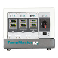
Mold-Masters TempMaster MT-06-06 User Manual (100 pages)
Brand:
Mold-Masters
| Category:
Temperature Controller
| Size: 4 MB
Table of Contents
Table of Contents
5
Section 1 - Introduction
10
Intended Use
10
Release Details
10
Warranty Details
10
Returned Goods Policy
10
Movement or Resale of Mold-Masters Products or Systems
10
Copyright
11
Units of Measure and Conversion Factors
11
Table 1-2 Units of Measure and Conversion Factors
11
Trademarks and Patents
12
Section 2 - Global Support
13
Manufacturing Facilities
13
Regional Offices
13
International Representatives
14
Section 3 - Safety
15
Introduction
15
Safety Hazards
16
Figure 3-1 Injection Molding Machine Hazard Areas
16
Table 3-1 Safety Hazards
18
Operational Hazards
19
General Safety Symbols
21
Table 3-2 Typical Safety Symbols
21
Wiring Check
22
Lockout Safety
23
Electrical Lockout
24
Energy Forms and Lockout Guidelines
25
Table 3-3 Energy Forms, Energy Sources and General
25
Disposal
26
MT/MT2 Controller User Hazards
27
Section 4 - Overview
29
Figure 4-1 MT Controller
29
Figure 4-2 MT2 Controller
29
Specification
30
Table 4-1 General Specifications
30
TMXL/MT Compatibility
30
Controller Power Supplies
31
Filter Option
31
Switch on and off
31
Switch on
31
Switch off Individual Modules
31
Switch off the Whole Controller
31
Switch off Individual Zones
32
Tool Connections
31
Controller Cabinet
32
Controller Modules
33
How the MT Controller Works
34
Set the Ramp Feature (on / Off)
34
Figure 4-3 MT Menu
35
Figure 4-4 MT2 Menu
35
Program Menus
35
Section 5 - Setup
36
Introduction
37
Table 5-1 Factory Settings
37
Set Zone Numbering
38
Set the Temperature Scale
40
Change Zone PID Characteristics
42
Set the Ramp Feature
44
Set Boost Value
46
Set Standby Value
48
Monitor Temperature Limits
50
Warning and Alarm Limits
50
Set Ground Fault Detection
52
Set Mold Leak Detection
54
Set Response to Thermocouple Failure
56
Restrict Access to Manual, Standby or Boost
58
Extend Alarms for Manual, Standby or Boost Operation
60
Language
62
Set the Required Zone Temperatures
63
Section 6 - Operation
64
Run Mode
64
OFF Mode (Single Zone)
65
Off Mode (Single Module)
65
Manual Mode
66
Manual Mode - Power Level
67
Slave Mode
68
Standby and Boost Mode
70
Standby - Whole Cabinet
70
Boost - Whole Cabinet
70
No Standby or Boost Option
70
Standby Mode - Individual Zones
71
Leaving Standby Mode
72
Boost Mode - Individual Zones
73
Change Set Temperature (Auto or Manual)
74
Section 7 - Maintenance
75
Service and Repair the Controller
75
Replacement Parts
75
Cleaning and Inspection
75
Restore Factory Settings and Recalibration
76
Default Settings
77
Calibration Routine
77
Calibration Sequence
77
Table 7-1 Factory Settings
77
M.dis Option
78
Fuses and Overcurrent Protection
79
Fans
79
Figure 7-1 Fuse Location on a Controller Card
79
Controller Cards
80
Onboard Power Supply
80
Output Fuse Type: HRC High Speed
80
Input Fuse Type: Surface-Mount Quick-Blow
80
Table 7-2 Fan Fuses
80
Table 7-3 Onboard Power Supply Fuse
80
Table 7-4 Output Fuse Type
80
Table 7-5 Input Fuse Type
80
Section 8 - Troubleshooting
81
Individual Card Diagnostics
81
Table 8-1 Alarm Conditions
81
Other Possible Fault Conditions
83
Rapid Temperature Fluctuations
83
Ground Fault Detection
83
Module Removal
83
Section 9 - Wiring Details
84
Single Phase Supply Cable
84
Table 9-1 Cable Markings for Single Phase Supply Cable
84
Three Phase Designation
85
Five Wire Star 380VAC
85
Table 9-2 Cable Markings - 5 Wire Star
85
Set Power Terminal Block to STAR Configuration
86
Figure 9-1 Connect the Neutral - Position Shown by Blue
86
Figure 9-2 Install the Three Way Link
86
For Four Wire Delta 240V
87
Table 9-3 Cable Markings for Four Wire Star
87
Set Power Terminal Block to DELTA Configuration
88
Figure 9-3 Remove the Neutral Wire - Position Shown by the
88
Figure 9-4 Install the Three 2-Way Links
88
Filter Option
89
Alarm Output
89
Table 9-4 HAN4A Pin Connections
89
Figure 9-5 HAN4A Connector
89
Standard Tool Connections
90
Mt-02-02
90
MT-02-02 for UK and Europe
90
Table 9-5 MT-02-02 Pin Configuration for UK and Europe
90
Figure 9-7 Harting Han 10 a ® Cut out Dimensions
90
MT-02-02 for India
91
Table 9-6 MT-02-02 Pin Configuration for India
91
MT-02-02 for North America
92
Table 9-7 MT-02-02 Pin Configuration for North America
92
Mt-04-04
93
Table 9-8 MT-04-04 Pin Configuration
93
Figure 9-12 Insert for MT-04-04
93
Figure 9-13 MT-04-04 Cut out Dimensions
93
Mt-06-06
94
Table 9-9 MT-06-06 Pin Configuration
94
Figure 9-14 Insert for MT-06-06
94
Figure 9-15 MT-06-06 Cut out Dimensions
94
MT-12-12 and MT-18-XX
95
MT-12-12 and MT-18-XX for UK and Europe
95
Figure 9-16 Inserts for MT-12-12 and MT-18-XX
95
Table 9-10 MT-12-12 / MT-18-XX Pin Configuration for UK and Europe
96
Figure 9-17 MT-12-12 and MT-18-XX Cut out Dimensions - UK and Europe
96
MT-12-12 and MT-18-XX for North America
97
Table 9-11 MT-12-12 / MT-18-XX Pin Configuration for North America (Plug 1)
97
Figure 9-18 MT-12-12 and MT-18-XX Inserts (Plug 1 and Plug 2)
97
Table 9-12 MT-12-12 / MT-18-XX Pin Configuration for North America (Plug 2)
98
Figure 9-19 MT-12-12 and MT-18-XX Cut out Dimensions - North America
98
Index
99
Advertisement
Advertisement
Related Products
Mold-Masters TempMaster MT-02-02
Mold-Masters TempMaster MT-04-04
Mold-Masters TempMaster MT-18 Series
Mold-Masters TempMaster MT2
Mold-Masters TempMaster MT-12-12
Mold-Masters TempMaster MT Series
Mold-Masters TempMaster MT
Mold-Masters M2
Mold-Masters TempMaster M1 Plus Series
Mold-Masters TempMasters Me12
Mold-Masters Categories
Controller
Industrial Equipment
Laboratory Equipment
Temperature Controller
More Mold-Masters Manuals
Login
Sign In
OR
Sign in with Facebook
Sign in with Google
Upload manual
Upload from disk
Upload from URL