Table of Contents
Advertisement
Quick Links
Advertisement
Table of Contents

Related Manuals for Mold-Masters TempMaster MT Series

Summary of Contents for Mold-Masters TempMaster MT Series
- Page 1 User Manual version 4 Original Instructions...
- Page 3 REMOVE AND KEEP THIS SHEET SOMEWHERE SAFE MT Controllers come with a fixed password which is entered via the two arrow keys. The Password is: (up, down, up, up, down) followed by a check mark...
-
Page 5: Table Of Contents
1.1 Intended Use ......................1-1 1.2 Release Details ....................1-1 1.3 Warranty Details ....................1-1 1.4 Returned Goods Policy ..................1-1 1.5 Movement or Resale of Mold-Masters Products or Systems ......................1-1 1.6 Copyright ......................1-2 1.7 Units of Measure and Conversion Factors ............1-2 1.8 Trademarks and Patents ..................1-3 Section 2 - Global Support ..........2-1... - Page 6 7.3 Fuses and Overcurrent Protection ..............7-5 7.3.1 Fans ......................7-5 7.3.2 Controller Cards ..................7-6 7.3.3 Onboard Power Supply ................7-6 7.3.4 Output Fuse Type: HRC High Speed ............7-6 7.3.5 Input Fuse Type: Surface-Mount Quick-Blow ..........7-6 © 2020 Mold-Masters (2007) Limited. All Rights Reserved. MT Controller User Manual...
- Page 7 9.5.5 MT-04-04 ....................9-10 9.5.6 MT-06-06 ....................9-11 9.5.7 MT-12-12 and MT-18-xx ................9-12 9.5.8 MT-12-12 and MT-18-xx for UK and Europe..........9-12 9.5.9 MT-12-12 and MT-18-xx for North America ..........9-14 Index ..................I MT Controller User Manual © 2020 Mold-Masters (2007) Limited. All Rights Reserved.
- Page 8 Europe .......................9-12 Table 9-11 MT-12-12 / MT-18-xx Pin Configuration for North America (Plug 1) ..................9-13 Table 9-12 MT-12-12 / MT-18-xx Pin Configuration for North America (Plug 2) ..................9-14 © 2020 Mold-Masters (2007) Limited. All Rights Reserved. MT Controller User Manual...
- Page 9 UK and Europe ....................9-12 Figure 9-18 MT-12-12 and MT-18-xx inserts (Plug 1 and Plug 2) ......9-13 Figure 9-19 MT-12-12 AND MT-18-xx cut out dimensions - North America ....................9-14 MT Controller User Manual © 2020 Mold-Masters (2007) Limited. All Rights Reserved.
-
Page 10: Section 1 - Introduction
Warranty details are provided with your order documentation. 1.4 Returned Goods Policy Please do not return any parts to Mold-Masters without pre-authorization and a return authorization number supplied by Mold-Masters. Our policy is one of continuous improvement and we reserve the right to alter product specifications at any time without giving notice. -
Page 11: Copyright
INTRODUCTION 1.6 Copyright © 2019 Milacron LLC. All Rights Reserved. Mold-Masters® and the Mold- Masters logo are trademarks of Milacron LLC and/or its affiliates Mold- Masters (2007) Limited, DME Company LLC, and Cimcool Fluid Technology. (collectively, “Milacron”). 1.7 Units of Measure and Conversion Factors... -
Page 12: Trademarks And Patents
Since the conditions of use are beyond our control, Mold-Masters disclaims any liability incurred in connection with the use of our products and information contained herein. No person is authorized to make any statement or recommendation not contained herein, and any such statement or recommendation so made shall not bind Mold-Masters. -
Page 13: Section 2 - Global Support
+39 049/5019955 El Marques, Queretaro C.P. 76246 fax: +39 049/5019951 Tel: +82-31-431-4756 Mexico italy@moldmasters.com korea@moldmasters.com tel: +52 442 713 5661 (sales) tel: +52 442 713 5664 (service) mexico@moldmasters.com MT Controller User Manual © 2020 Mold-Masters (2007) Limited. All Rights Reserved. -
Page 14: International Representatives
SLOVENIA ROMANIA RD Picta Tehnologije d.o.o. Tehnic Mold Trade SRL tel: +386 59 969 117 tel: +4 021 230 60 51 e: info@picta.si e: contact@matritehightech.ro © 2020 Mold-Masters (2007) Limited. All Rights Reserved. MT Controller User Manual... -
Page 15: Section 3 - Safety
SAFETY Section 3 - Safety 3.1 Introduction Please be aware that the safety information provided by Mold-Masters does not absolve the integrator and employer from understanding and following international and local standards for safety of machinery. It is the responsibility of the end integrator to integrate the final system, provide... -
Page 16: Safety Hazards
9. Hoses 10. Area inside the guards and outside the mold area Front view with guards removed Front View with Guards Removed Figure 3-1 Injection molding machine hazard areas © 2020 Mold-Masters (2007) Limited. All Rights Reserved. MT Controller User Manual... - Page 17 Hazards due to reduction in mechanical strength of the plasticizing and / or injection cylinder due to overheating. Feed Opening Pinching and crushing between injection screw movement and housing. See Figure 3-1 area 6 MT Controller User Manual © 2020 Mold-Masters (2007) Limited. All Rights Reserved.
-
Page 18: Table 3-1 Safety Hazards
Crush or impact hazards caused by the movement of the power operated Gate gates. Vapors and Gases Certain processing conditions and / or resins can cause hazardous fumes or vapors. © 2020 Mold-Masters (2007) Limited. All Rights Reserved. MT Controller User Manual... -
Page 19: Operational Hazards
• Make sure that the cables are connected to the correct motors. Cables and motors are clearly labeled. Reversing the cables can result in unexpected and uncontrolled motion causing a safety risk or damage to the machine. MT Controller User Manual © 2020 Mold-Masters (2007) Limited. All Rights Reserved. - Page 20 Failure to support the machine can result in severe injury or death. • Mold cable from the controller to the mold must be removed before servicing the mold. © 2020 Mold-Masters (2007) Limited. All Rights Reserved. MT Controller User Manual...
-
Page 21: General Safety Symbols
Warning – Slip, Trip or Fall Hazard Do not climb on equipment surfaces. Serious slip, trip, or fall injuries can result from personnel climbing on equipment surfaces. MT Controller User Manual © 2020 Mold-Masters (2007) Limited. All Rights Reserved. -
Page 22: Wiring Check
/ or equipment. Failure to do wiring or connections properly will result in equipment failure. The use of Mold-Masters standard connections can help to eliminate the potential for wiring errors. Mold-Masters Ltd. cannot be responsible for damage caused by customer wiring and / or connection errors. -
Page 23: Lockout Safety
• Burns from contact with hot parts, materials or equipment such as furnaces • Fires and explosions • Chemical exposures from gases or liquids released from pipelines MT Controller User Manual © 2020 Mold-Masters (2007) Limited. All Rights Reserved. -
Page 24: Electrical Lockout
The last lock to be removed should be that of the person supervising the lockout and this responsibility should not be delegated. © Industrial Accident Prevention Association, 2008. © 2020 Mold-Masters (2007) Limited. All Rights Reserved. MT Controller User Manual... -
Page 25: Energy Forms And Lockout Guidelines
Shut off, lock (with chains, built- • Storage tanks and vessels in lockout devices, or lockout attachments) and tag valves. • Bleed off excess liquids or gases. • Blank lines as necessary. MT Controller User Manual © 2020 Mold-Masters (2007) Limited. All Rights Reserved. -
Page 26: Disposal
3-12 3.8 Disposal WARNING Milacron Mold-Masters declines any responsibility for personal injury or personal damage arising from reuse of the individual components, if these parts are used other than for the original and proper intended purpose. 1. Hot runner and system components must be disconnected from the power supply fully and properly before disposal, including electricity, hydraulics, pneumatics and cooling. -
Page 27: Mt/Mt2 Controller User Hazards
The controller cabinet and touchscreen console should be installed in a clean dry environment where the ambient conditions do not exceed the following limits: • Temperature +5 to +45°C • Relative Humidity 90% (non-condensing) MT Controller User Manual © 2020 Mold-Masters (2007) Limited. All Rights Reserved. -
Page 29: Section 4 - Overview
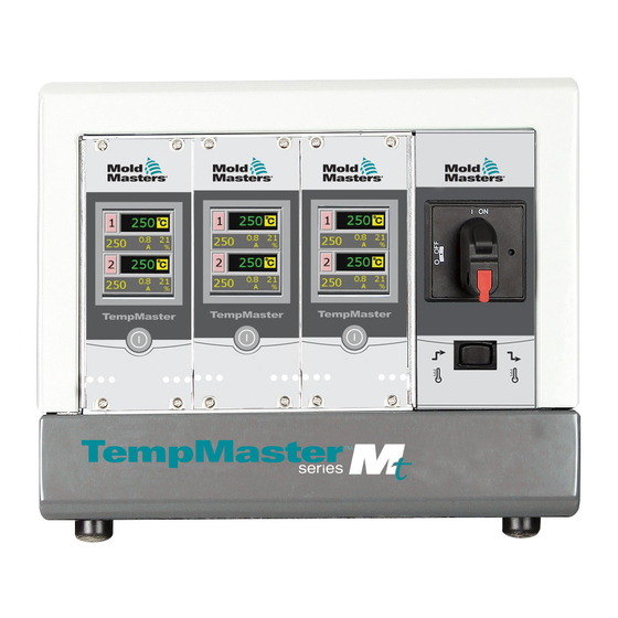
This manual will use MT to refer to both controllers, and it will specifically note if there is a difference between the two controllers. Figure 4-1 MT controller Figure 4-2 MT2 controller MT Controller User Manual © 2020 Mold-Masters (2007) Limited. All Rights Reserved. -
Page 30: Specification
In the TMXL2, output fuses were located under the cover, which meant the system had to be shutdown to gain safe access to replace a ruptured fuse. © 2020 Mold-Masters (2007) Limited. All Rights Reserved. MT Controller User Manual... -
Page 31: Tool Connections
“Section 2 - Global Support” on page 2-1 4.5 Filter Option In countries where noise across power lines is a concern, Mold-Masters recommends that you fit the model 63AYC10B in-line filter which is supplied by TC Connectivity. -
Page 32: Switch Off Individual Zones
Connections to the tool as standard are either by a mixed power and thermocouple cable, or individual power cable(s) and individual thermocouple cable(s). Mold-Masters standard wiring details are shown in “Section 9 - Wiring Details”. For MT-02-02 Controller: The power supply to the control cabinet is via a strain relief cable gland plug provided for single phase configuration. -
Page 33: Controller Modules
Output Triacs The controller card has a pair of on-board triacs that are capable of controlling heating loads of up to 16 Amps peak. MT Controller User Manual © 2020 Mold-Masters (2007) Limited. All Rights Reserved. -
Page 34: How The Mt Controller Works
OVERVIEW 4.8 How the MT Controller Works Mold-Masters controllers are designed to perform in closed and open loop configurations. We consider that the normal operating mode is closed loop. This is illustrated in the following diagram and explained below. The zone controller slowly ramps up the heater power and simultaneously looks for a positive temperature change at the thermocouple input. -
Page 35: Program Menus
“Section 5 - Setup” on page 5-1 and in “Section 6 - Operation” on page 6-1. Figure 4-3 MT Menu Figure 4-4 MT2 Menu MT Controller User Manual © 2020 Mold-Masters (2007) Limited. All Rights Reserved. -
Page 36: Section 5 - Setup
Refer to the serial plate on the controller cabinet for confirmation of the main supply requirements. If the local supply is outside the specified range, please contact Mold-Masters for advice. WARNING - ELECTRIC SHOCK HAZARD It is crucial to comply with these warnings to minimize any personal danger. -
Page 37: Introduction
It is possible to restore the default settings at any time. See “Restore Factory Settings and Recalibration” on page 7-2. © 2020 Mold-Masters (2007) Limited. All Rights Reserved. MT Controller User Manual... -
Page 38: Set Zone Numbering
1. From the Temperature Display screen, choose either zone to obtain the initial menu. 2. Choose [ ] to obtain the Function menu. 3. Choose [Program] to obtain the Program menu. MT Controller User Manual © 2020 Mold-Masters (2007) Limited. All Rights Reserved. - Page 39 5. Choose [Zone#] to open the zone numbering option. 6. Use [] or [] to set the required zone number. 7. Choose [ ] twice to return to the main display. © 2020 Mold-Masters (2007) Limited. All Rights Reserved. MT Controller User Manual...
-
Page 40: Set The Temperature Scale
3. Choose [Program] to obtain the Program menu. 4. Choose [ ] or [ ] to find the page containing a C/F option. 5. Choose [C/F] to open the Temperature Scale option. MT Controller User Manual © 2020 Mold-Masters (2007) Limited. All Rights Reserved. - Page 41 6. Select either [C] or [F] to suit the local operating preference. 7. Choose [ ] twice to return to the main display. The main display is now in Celsius. © 2020 Mold-Masters (2007) Limited. All Rights Reserved. MT Controller User Manual...
-
Page 42: Change Zone Pid Characteristics
2. Choose [ ] to obtain the Function menu. 3. Choose [Program] to obtain the Program menu. 4. Choose [ ] or [ ] to find the page containing the PID option. MT Controller User Manual © 2020 Mold-Masters (2007) Limited. All Rights Reserved. - Page 43 5. Choose [PID] and select an alternative timing. Blue ring shows speed chosen 6. Choose [ ] twice to return to the main display. The system is now set to run at the chosen speed. © 2020 Mold-Masters (2007) Limited. All Rights Reserved. MT Controller User Manual...
-
Page 44: Set The Ramp Feature
2. Choose [ ] to obtain the Function menu. 3. Choose [Program] to obtain the Program menu. 4. Choose [ ] or [ ] to find the page containing the Ramp option. MT Controller User Manual © 2020 Mold-Masters (2007) Limited. All Rights Reserved. - Page 45 SETUP 5-10 Set the Ramp Feature - continued 5. Choose [Ramp] and set it to Off. 6. Choose [ ] twice to return to the main display. © 2020 Mold-Masters (2007) Limited. All Rights Reserved. MT Controller User Manual...
-
Page 46: Set Boost Value
1. From the Temperature Display screen, choose either zone to obtain the initial menu. 2. Choose [ ] to obtain the Function menu. 3. Choose [Program] to obtain the Program menu. MT Controller User Manual © 2020 Mold-Masters (2007) Limited. All Rights Reserved. - Page 47 [Boost] to open the value setting option. 5. Use [ ] or [ ] to set the desired Boost temperature. 6. Choose [ ] twice to return to the main display. © 2020 Mold-Masters (2007) Limited. All Rights Reserved. MT Controller User Manual...
-
Page 48: Set Standby Value
3. Choose [Program] to obtain the Program menu. 4. Choose [ ] or [ ] to find the page containing a Standby option. Choose the [Standby] button to open the value setting option. MT Controller User Manual © 2020 Mold-Masters (2007) Limited. All Rights Reserved. - Page 49 You can hold the [ ] or [ ] buttons down to raise or lower value by large amounts. 6. Choose [ ] twice to return to the main display. © 2020 Mold-Masters (2007) Limited. All Rights Reserved. MT Controller User Manual...
-
Page 50: Monitor Temperature Limits
2. Choose [ ] to obtain the Function menu. 3. Choose [Program] to obtain the Program menu. 4. Choose [Ot] to open the value setting option. MT Controller User Manual © 2020 Mold-Masters (2007) Limited. All Rights Reserved. - Page 51 6. Choose [ ] to return then [Ut] to open the Under Temperature limit. Use [ ] or [ ] to set the desired Under Temperature limit. 7. Choose [ ] twice to return to the main display. © 2020 Mold-Masters (2007) Limited. All Rights Reserved. MT Controller User Manual...
-
Page 52: Set Ground Fault Detection
2. Choose [ ] to obtain the Function menu. 3. Choose [Program] to obtain the Program menu. 4. Choose [ ] or [ ] to find the page containing the Ground selection option. MT Controller User Manual © 2020 Mold-Masters (2007) Limited. All Rights Reserved. - Page 53 Set Ground Fault Detection - continued 5. Choose [Gnd] to open the page and set it to On or Off as required. 6. Choose [ ] twice to return to the main display. © 2020 Mold-Masters (2007) Limited. All Rights Reserved. MT Controller User Manual...
-
Page 54: Set Mold Leak Detection
1. Choose [ ] to obtain the Function menu. 2. Choose [Program] to obtain the Program menu. 3. Choose [ ] or [ ] to find the page containing the Leak option. MT Controller User Manual © 2020 Mold-Masters (2007) Limited. All Rights Reserved. - Page 55 4. Choose [Leak] to open the page then choose [ ] or [ ] to set the Leak detection power level. 5. Choose [ ] twice to return to the main display. © 2020 Mold-Masters (2007) Limited. All Rights Reserved. MT Controller User Manual...
-
Page 56: Set Response To Thermocouple Failure
2. Choose [ ] to obtain the Function menu. 3. Choose [Program] to obtain the Program menu. 4. Choose [] or [] to find the page containing the Auto-Man option. MT Controller User Manual © 2020 Mold-Masters (2007) Limited. All Rights Reserved. - Page 57 Set Response to Thermocouple Failure - continued 5. Choose [Auto-man] to open the page and set it to On. 6. Choose [ ] twice to return to the main display. © 2020 Mold-Masters (2007) Limited. All Rights Reserved. MT Controller User Manual...
-
Page 58: Restrict Access To Manual, Standby Or Boost
2. Choose [Program] to obtain the Program menu. 3. Choose [] or [] to find the page containing a [Factory] option. 4. Enter the password and then choose [ ] to access the next screen. MT Controller User Manual © 2020 Mold-Masters (2007) Limited. All Rights Reserved. - Page 59 8. To reset return to the Factory box and uncheck M.Dis. NOTE Selecting this option will inhibit the front panel rocker switch so that Standby or Boost selection will also be ineffective. © 2020 Mold-Masters (2007) Limited. All Rights Reserved. MT Controller User Manual...
-
Page 60: Extend Alarms For Manual, Standby Or Boost Operation
2. Choose [ ] to obtain the Function menu. 3. Choose [Program] to obtain the Program menu. 4. Choose [] or [] to find the page containing the Alarm option. MT Controller User Manual © 2020 Mold-Masters (2007) Limited. All Rights Reserved. - Page 61 6. Choose [ ] once to return to the Alarm selection in order to select more Alarm options. 7. Choose [ ] a second time to return to the main display. © 2020 Mold-Masters (2007) Limited. All Rights Reserved. MT Controller User Manual...
-
Page 62: Language
3. Choose [Program] to obtain the Program menu. 4. Choose [] or [] to find the page containing the Language option. 5. Choose [Language] to open the page and set it to the required language. MT Controller User Manual © 2020 Mold-Masters (2007) Limited. All Rights Reserved. -
Page 63: Set The Required Zone Temperatures
] or [ ] buttons down to raise or lower value by large amounts. 3. Choose [ ] to return to the main display. Repeat for other zones. © 2020 Mold-Masters (2007) Limited. All Rights Reserved. MT Controller User Manual... -
Page 64: Section 6 - Operation
2. Choose that zone, and then choose [ ] to start. 3. Choose [ ] to return to main screen and see zone 1 now in Auto-Run mode. Repeat these steps for the other zone if needed. MT Controller User Manual © 2020 Mold-Masters (2007) Limited. All Rights Reserved. -
Page 65: Off Mode (Single Zone)
NOTE This section is not applicable for the MT-02-02 controller. 1. Turn the module off by choosing the [ ] button on the front of the individual card. © 2020 Mold-Masters (2007) Limited. All Rights Reserved. MT Controller User Manual... -
Page 66: Manual Mode
3. Choose [Manual] to enter Manual mode and go to open loop working. 4. Choose [ ] to return to main display and see that zone 1 is now running in Manual mode. MT Controller User Manual © 2020 Mold-Masters (2007) Limited. All Rights Reserved. -
Page 67: Manual Mode - Power Level
6.5 Manual Mode - Power Level 1. Choose the Manual zone to obtain the initial menu. 2. Choose [] to raise or [] to lower the power setting and consequently the temperature. © 2020 Mold-Masters (2007) Limited. All Rights Reserved. MT Controller User Manual... -
Page 68: Slave Mode
1. From the Temperature Display Screen, choose either zone to obtain the initial menu. 2. Choose [ ] to obtain the Function menu. 3. Choose [Program] and use [] or [] to find Slave. 4. Choose [Slave]. MT Controller User Manual © 2020 Mold-Masters (2007) Limited. All Rights Reserved. - Page 69 6. Choose [ ] twice to return to main display, and see that zone 1 displays “S2” to indicate it is slaved to zone 2. 7. To restore to Auto mode, repeat the first five above steps and select Slave [Off]. © 2020 Mold-Masters (2007) Limited. All Rights Reserved. MT Controller User Manual...
-
Page 70: Standby And Boost Mode
[ ] to obtain the Function menu. If the three buttons are greyed out, as shown in the picture below, then Standby and Boost are not available. MT Controller User Manual © 2020 Mold-Masters (2007) Limited. All Rights Reserved. -
Page 71: Standby Mode - Individual Zones
NOTE If the screen in this step shows the Manual, Standby and Boost buttons greyed out then this function has been inhibited. See page 5-23 for more information. © 2020 Mold-Masters (2007) Limited. All Rights Reserved. MT Controller User Manual... -
Page 72: Leaving Standby Mode
Actual Temperature window. 6.9 Leaving Standby Mode 1. Choose the Standby zone to obtain the initial menu. 2. Choose [ ] to leave Standby mode and revert to Auto mode. MT Controller User Manual © 2020 Mold-Masters (2007) Limited. All Rights Reserved. -
Page 73: Boost Mode - Individual Zones
See page 5-23 for more information. The screen reverts to main display but you can see the boosted temperature and confirmation message “tup” will flash alternately in the Actual Temperature window. © 2020 Mold-Masters (2007) Limited. All Rights Reserved. MT Controller User Manual... -
Page 74: Change Set Temperature (Auto Or Manual)
Choose [ ] to revert to main display. 2. Decrease Setting: Choose the zone to display the initial menu and choose [] to lower the temperature. Choose [ ] to revert to main display. MT Controller User Manual © 2020 Mold-Masters (2007) Limited. All Rights Reserved. -
Page 75: Section 7 - Maintenance
If the equipment is subject to vibration then we recommend that you use an insulated screwdriver to check that no terminals have become loose. MT Controller User Manual © 2020 Mold-Masters (2007) Limited. All Rights Reserved. -
Page 76: Restore Factory Settings And Recalibration
Defaults – restore the unit to default settings • CAL – enter a calibration check routine • M.Dis – enable or disable user options These are described on the next page. © 2020 Mold-Masters (2007) Limited. All Rights Reserved. MT Controller User Manual... -
Page 77: Default Settings
6. The screen timer counts down as it sets the high range setting. 7. The screen informs you that the calibration has completed. 8. Remove the thermocouple simulator and temporary connector. MT Controller User Manual © 2020 Mold-Masters (2007) Limited. All Rights Reserved. -
Page 78: M.dis Option
MAINTENANCE 7.2.4 M.Dis Option A user can be prevented from choosing Manual Control, Standby or Boost function if the M.Dis (Manual Disabled) box is selected on this screen: © 2020 Mold-Masters (2007) Limited. All Rights Reserved. MT Controller User Manual... -
Page 79: Fuses And Overcurrent Protection
If the fan is free to rotate, then check the panel-mounted fuse at the rear of the unit. 1. Input fuses 2. PSU fuses 3. Output fuses Figure 7-1 Fuse location on a controller card MT Controller User Manual © 2020 Mold-Masters (2007) Limited. All Rights Reserved. -
Page 80: Controller Cards
If the module shows a “T/C” alarm then this may indicate that the input fuse has ruptured. The card may be easily removed and the fuse changed. Table 7-5 Input Fuse Type Part Code Nano Ceramic Very fast Rating 62mA © 2020 Mold-Masters (2007) Limited. All Rights Reserved. MT Controller User Manual... -
Page 81: Section 8 - Troubleshooting
The system has detected an earth fault. Check the heater wiring for a low impedance path to earth. MT Controller User Manual © 2020 Mold-Masters (2007) Limited. All Rights Reserved. - Page 82 T/C Open Error column of adjacent zone or change to open the Setup page. loop control. © 2020 Mold-Masters (2007) Limited. All Rights Reserved. MT Controller User Manual...
-
Page 83: Other Possible Fault Conditions
To remove a control module from its slot, unscrew the four corner screws first. There is no need to switch off the main supply. However, if operational requirements allow, the cabinet may be isolated. MT Controller User Manual © 2020 Mold-Masters (2007) Limited. All Rights Reserved. -
Page 84: Section 9 - Wiring Details
Incorrect connection may appear to work but can result in damage to the controller. The following standards only apply to controllers wired to Mold-Masters standard. Other specifications may have been stated when the controller was ordered. Please refer to the supplied specification details. -
Page 85: Three Phase Designation
Phase 1 Grey Phase 2 Brown Phase 3 Blue Neutral Green / yellow Earth See “9.2.2 Set Power Terminal Block to STAR Configuration” on page 9-3 for more information. © 2020 Mold-Masters (2007) Limited. All Rights Reserved. MT Controller User Manual... -
Page 86: Set Power Terminal Block To Star Configuration
2. Join MP1, MP2 and MP3 to the blue N conductor on the terminal block. Refer to Figure 9-2. Output to busbars Figure 9-2 Install the three way link MT Controller User Manual © 2020 Mold-Masters (2007) Limited. All Rights Reserved. -
Page 87: For Four Wire Delta 240V
Black Phase 1 Grey Phase 2 Brown Phase 3 Green / yellow Earth See “9.2.4 Set Power Terminal Block To DELTA Configuration” on page 9-5 for more information. © 2020 Mold-Masters (2007) Limited. All Rights Reserved. MT Controller User Manual... -
Page 88: Set Power Terminal Block To Delta Configuration
2. Join MP3, MP1 and MP2 with the three 2-way links. Refer to Figure 9-4. Output to busbars Figure 9-4 Install the three 2-way links IMPORTANT Do not link MP1, MP3 and MP2 together. MT Controller User Manual © 2020 Mold-Masters (2007) Limited. All Rights Reserved. -
Page 89: Filter Option
WIRING DETAILS 9.3 Filter Option In countries where noise across power lines is a concern, Mold-Masters recommends that an inline filter is fitted. Please contact Mold-Masters for details. 9.4 Alarm Output NOTE This section is not applicable for the MT-02-02 controller. -
Page 90: Standard Tool Connections
Pin 6 Pin 7 The cut out dimensions are shown in Figure 9-6. Figure 9-7 Harting Han 10 A cut out dimensions ® Maximum voltage: 220VAC - 10A. MT Controller User Manual © 2020 Mold-Masters (2007) Limited. All Rights Reserved. -
Page 91: Mt-02-02 For India
Pin 3 Pin 4 The cut out dimensions are shown in Figure 9-9 Figure 9-9 Harting Han 16 E cut out dimensions ® Maximum voltage: 220VAC - 10A. © 2020 Mold-Masters (2007) Limited. All Rights Reserved. MT Controller User Manual... -
Page 92: Mt-02-02 For North America
Pin 9 Pin 10 The cut out dimensions are shown in Figure 9-11. Figure 9-11 Harting Han 10 E cut out dimensions ® Maximum voltage: 220VAC - 10A. MT Controller User Manual © 2020 Mold-Masters (2007) Limited. All Rights Reserved. -
Page 93: Mt-04-04
Pin 15 Pin 16 Pin 7 Pin 8 The cut out dimensions are shown in Figure 9-13. Figure 9-13 MT-04-04 cut out dimensions Maximum voltage: 230VAC - 16A © 2020 Mold-Masters (2007) Limited. All Rights Reserved. MT Controller User Manual... -
Page 94: Mt-06-06
Pin 11 Pin 12 Pin 23 Pin 24 The cut out dimensions are shown in Figure 9-15. Figure 9-15 MT-06-06 cut out dimensions Maximum voltage: 230VAC - 16A MT Controller User Manual © 2020 Mold-Masters (2007) Limited. All Rights Reserved. -
Page 95: Mt-12-12 And Mt-18-Xx
It is the responsibility of the integrator to identify and implement the correct tool wiring. 9.5.8 MT-12-12 and MT-18-xx for UK and Europe Figure 9-16 Inserts for MT-12-12 and MT-18-xx © 2020 Mold-Masters (2007) Limited. All Rights Reserved. MT Controller User Manual... -
Page 96: Table 9-10 Mt-12-12 / Mt-18-Xx Pin Configuration For Uk And Europe
Pin 24 The cut out dimensions are shown in Figure 9-17. Figure 9-17 MT-12-12 AND MT-18-xx cut out dimensions - UK and Europe Maximum voltage: 230VAC - 16A MT Controller User Manual © 2020 Mold-Masters (2007) Limited. All Rights Reserved. -
Page 97: Mt-12-12 And Mt-18-Xx For North America
Pin 9 Pin 21 Pin 10 Pin 22 Pin 10 Pin 22 Pin 11 Pin 23 Pin 11 Pin 23 Pin 12 Pin 24 Pin 12 Pin 24 © 2020 Mold-Masters (2007) Limited. All Rights Reserved. MT Controller User Manual... -
Page 98: Table 9-12 Mt-12-12 / Mt-18-Xx Pin Configuration For North America (Plug 2)
Pin 12 Pin 24 The cut out dimensions are shown in Figure 9-19. Figure 9-19 MT-12-12 AND MT-18-xx cut out dimensions - North America Maximum voltage: 230VAC - 16A MT Controller User Manual © 2020 Mold-Masters (2007) Limited. All Rights Reserved. -
Page 99: Index
How the MT Controller Works 4-6 Zone Numbering 5-3 Zone Temperatures 5-28 Inhibiting Manual, Standby or Boost 5-24 Language 5-27 Mold Leak Detection 5-19 Operation Principles 6-1 PID Characteristics 5-7 Ramp 5-9 MT Controller User Manual © 2020 Mold-Masters (2007) Limited. All Rights Reserved. - Page 100 +44 1432 263782 fax: +65 6261 8378 e: uk@moldmasters.com e: singaore@moldmasters.com Turkey Mold-Masters Europa GmbH Tel: +90 216 577 32 44 Fax: +90 216 577 32 45 e: turkey@moldmasters.com www.moldmasters.com © 2020 Mold-Masters (2007) Limited. All Rights Reserved. MT Controller User Manual...
Need help?
Do you have a question about the TempMaster MT Series and is the answer not in the manual?
Questions and answers