Sign In
Upload
Manuals
Brands
MKS Manuals
Controller
Mass-Flo 1479A
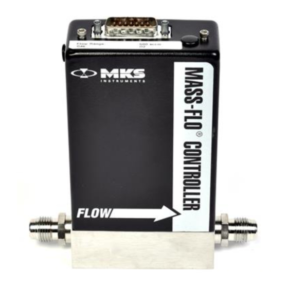
User Manuals: MKS Mass-Flo 1479A Mass Flow Controller
Manuals and User Guides for MKS Mass-Flo 1479A Mass Flow Controller. We have
1
MKS Mass-Flo 1479A Mass Flow Controller manual available for free PDF download: Instruction Manual
MKS Mass-Flo 1479A Instruction Manual (72 pages)
Brand:
MKS
| Category:
Controller
| Size: 0 MB
Table of Contents
Table of Contents
5
Mass Flow Controller Safety Information
11
Symbols Used in this Instruction Manual
11
Symbols Found on the Unit
12
Table 1: Definition of Symbols Found on the Unit
12
Safety Procedures and Precautions
13
Chapter One: General Information
15
Introduction
15
Design Features
15
Reliability
16
Cleanliness Features
16
How this Manual Is Organized
17
Customer Support
18
Chapter Two: Installation
19
How to Unpack the Type 1479 Controller
19
Opening the Package
19
Unpacking Checklist
20
Environmental Requirements
20
Setup
21
Dimensions
22
Figure 1: Outline Dimensions of the 1479 Flow Controller
22
Gas Line Connections
23
Standard Fittings
23
Optional Fittings
23
Mounting a Type 1479 MFC
23
Figure 2: Side View of the 1479 Flow Controller
23
Figure 3: Mounting Dimensions of the 1479 Flow Controller
24
The Type 2479 MFC
25
Mounting a Type 2479 MFC
25
Figure 4: Outline Dimensions of the Type 2479 Unit
25
Figure 5: Mounting Dimensions of the Type 2479 Flow Controller
25
Interface Cables
26
Table 2: MKS Interface Cables
26
Generic Shielded Cable Description
27
Example 1: Preferred Method to Connect Cable
28
Example 2: Alternate Method to Connect Cable
28
Figure 6: Preferred Method
28
Figure 7: Alternate Method to Use When Cable Clamp Is Not Available
28
Chapter Three: Overview
29
Electrical Connections
29
9-Pin Type "D" Connector
29
Table 3: 9-Pin Type "D" Connector Pinout
29
15-Pin Type "D" Connector
30
Table 4: 15-Pin Type "D" Connector Pinout
30
P.C. Edge Card Connector
31
Table 5: 20-Pin Edge Card Connector Pinout
31
The Gas Correction Factor (GCF)
32
Control Valve
33
Chapter Four: Operation
35
How to Start up the Flow Controller
35
How to Zero the Flow Controller
36
How to Adjust the Controller Gain
37
How to Override the Valve
38
Priority of the Commands
38
The Optional Input
39
Chapter Five: Theory of Operation
41
Flow Path
41
Measurement Technique
41
Control Circuitry
42
Chapter Six: Maintenance
43
General
43
Zero Adjustment
43
Chapter Seven: Troubleshooting
45
Troubleshooting
45
Table 6: Troubleshooting Chart
45
How to Adjust the Valve Preload
47
Figure 8: Location of the Retaining Screws
48
Figure 9: Location of the Jam Nut and Adjustment Nut
49
Table 7: Maximum Valve Current
50
Figure 10: the PC Board
51
Table 8: Required Valve Current Headroom
52
Appendix A: Product Specifications
53
Performance Specifications
53
Environmental Specifications
54
Electrical Specifications
54
Physical Specifications
55
Appendix B: Gas Correction Factors
57
Appendix C: MFC Sizing Guidelines
61
General Information
61
How to Determine the Flow Controller Range
62
How to Determine the Valve Configuration
63
Table 9: C V Pressure Factors
63
Table 10: Valve Configuration Selection Guide
64
Appendix D: Model Code
67
Model Code
67
Index
71
Advertisement
Advertisement
Related Products
MKS 1579A
MKS 1579B
MKS 153D
MKS Mass-Flo 1500 Series
MKS Mass-Flo 1562A
MKS Mass-Flo 1159B
MKS Mass-Flo 1160B
MKS 1152C
MKS Mass-Flo 1162B
MKS Mass-Flo 1679B
MKS Categories
Controller
Measuring Instruments
Transducer
Control Unit
Industrial Equipment
More MKS Manuals
Login
Sign In
OR
Sign in with Facebook
Sign in with Google
Upload manual
Upload from disk
Upload from URL