Sign In
Upload
Manuals
Brands
Miller Manuals
Welding System
XMT 450 CC
Miller XMT 450 CC Multi-process Welder Manuals
Manuals and User Guides for Miller XMT 450 CC Multi-process Welder. We have
3
Miller XMT 450 CC Multi-process Welder manuals available for free PDF download: Technical Manual, Owner's Manual
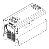
Miller XMT 450 CC Technical Manual (84 pages)
Brand:
Miller
| Category:
Welding System
| Size: 2 MB
Table of Contents
Table of Contents
2
Section 1 − Safety Precautions for Servicing
5
Symbol Usage
5
Servicing Hazards
5
California Proposition 65 Warnings
6
EMF Information
6
Section 2 − Definitions
7
Additional Safety Symbols and Definitions
7
Miscellaneous Symbols and Definitions
9
Section 3 − Specifications
10
Features and Benefits
10
Arc Controls
10
Serial Number and Rating Label Location
10
Unit Specifications
10
Dimensions and Weight
11
Environmental Specifications
11
Duty Cycle and Overheating
12
Volt-Ampere Curves
13
Section 4 − Installation
14
Selecting a Location
14
Weld Output Terminals and Selecting Cable Sizes
15
Connecting Weld Output Cables
16
Remote 14 Receptacle Information
16
115 Volts AC Duplex Receptacle and Supplementary Protectors
17
Optional Gas Valve Operation and Shielding Gas Connection
18
Electrical Service Guide
19
Connecting Input Power
20
Section 5 − General Operation
22
Front Panel
22
Mode Switch Settings
23
Section 6 − Gtaw Operation
24
Typical Connection for GTAW Process
24
Scratch Start TIG Welding Mode - GTAW Process
25
Lift-Arc TIG Welding Mode - GTAW Process
26
Remote Scratch Start TIG Welding Mode - GTAW Process
27
Section 7 − Gmaw/Fcaw Operation
28
Typical Connection for Remote Control Feeder GMAW/FCAW Process
28
MIG Welding Mode - GMAW/FCAW Process
29
Typical Connection for Remote Control Feeder GMAW-P Process
30
Pulsed MIG Welding Mode - GMAW-P Process
31
Typical Connection for Voltage-Sensing Feeder GMAW/FCAW Process
32
V-Sense Feeder Welding Mode - GMAW/FCAW Process
33
Section 8 − Smaw/Cac-A Operation
34
Typical Connection for SMAW and CAC-A Process
34
Remote Stick Welding Mode - SMAW/CAC-A Process
35
Stick Welding Mode - SMAW/CAC-A Process
36
Optional Low Open Circuit Voltage (OCV) Welding Modes
37
Alternate Configuration Functions
37
Section 9 − Theory of Operation
38
Section 10 − Troubleshooting
41
Checking Unit before Applying Power
41
Removing Case and Measuring Input Capacitor Voltage
42
Input Rectifier SR1
43
IGBT Modules PM1, PM2
44
Interconnect Board PC2
45
Output Diodes
46
Input Contactor W1
47
Tank Capacitors
47
Troubleshooting Table
48
Help Codes
49
Troubleshooting Circuit Diagram for Welding Power Source (All Models) (Use with Section 10-12)
52
Readings for Troubleshooting Circuit Diagram (All Models) (Use with Section 10-11)
54
Inverter Control Board PC1 Testing Information (Use with Section 10-14)
56
Inverter Control Boards PC1 Test Point Values
57
Inverter Control Board PC1 Diagnostic Leds
58
Interconnect Board PC2 Testing Information (Use with Section 10-17)
60
Interconnect Board PC2 Test Point Values
61
Front Panel/Display Board PC3 Testing Information (Use with Section 10-19)
62
Front Panel/Display Board PC3 Test Point Values
63
Checking Unit Output after Servicing
64
Enabling Low Open Circuit Voltage Welding Modes (Optional)
65
Checking Bus Voltage Imbalance
66
Section 11 − Maintenance
67
Routine Maintenance
67
Blowing out Inside of Unit
67
Section 12 − Electrical Diagram
69
Section 13 − Parts List
78
Advertisement
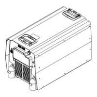
Miller XMT 450 CC Owner's Manual (57 pages)
Brand:
Miller
| Category:
Welding System
| Size: 2 MB
Table of Contents
Table of Contents
4
Section 1 − Safety Precautions - Read before Using
6
Symbol Usage
6
Arc Welding Hazards
6
Additional Symbols for Installation, Operation, and Maintenance
8
California Proposition 65 Warnings
9
Principal Safety Standards
9
EMF Information
9
Section 2 − Consignes de Sécurité − Lire Avant Utilisation
10
Symboles Utilisés
10
Dangers Relatifs au Soudage à L'arc
10
Dangers Supplémentaires en Relation Avec L'installation, le Fonctionnement et la Maintenance
12
Proposition Californienne 65 Avertissements
13
Principales Normes de Sécurité
13
Informations Relatives aux CEM
13
Section 3 − Definitions
14
Additional Safety Symbols and Definitions
14
Miscellaneous Symbols and Definitions
15
Section 4 − Specifications
16
Features and Benefits
16
Arc Controls
16
Serial Number and Rating Label Location
16
Unit Specifications
16
Dimensions and Weight
17
Environmental Specifications
17
Duty Cycle and Overheating
18
Volt-Ampere Curves
19
Section 5 − Installation
20
Selecting a Location
20
Selecting Input Voltage (230/460 Volt Models Only)
21
Selecting Cable Sizes
22
Weld Output Terminals
22
Connecting Weld Output Cables
23
Remote 14 Receptacle Information
23
Supplementary Protector
24
Optional Gas Valve Operation and Shielding Gas Connection
25
Electrical Service Guide
26
Connecting Input Power
27
Section 6 − General Operation
29
Front Panel
29
Mode Switch Settings
30
Section 7 − Gtaw Operation
31
Typical Connection for GTAW Process
31
Scratch Start TIG Welding Mode - GTAW Process
32
Lift-Arc TIG Welding Mode - GTAW Process
33
TIG Welding Mode - GTAW Process
34
Section 8 − Gmaw/Fcaw Operation
35
Typical Connection for Remote Control Feeder GMAW/FCAW Process
35
MIG Welding Mode - GMAW/FCAW Process
36
Typical Connection for Remote Control Feeder GMAW-P Process
37
Pulsed MIG Welding Mode - GMAW-P Process
38
Typical Connection for Voltage-Sensing Feeder GMAW/FCAW Process
39
V-Sense Feeder Welding Mode - GMAW/FCAW Process
40
Section 9 − Smaw/Cac-A Operation
41
Typical Connection for SMAW and CAC-A Process
41
CC Welding Mode - SMAW/CAC-A Process
42
Stick Welding Mode - SMAW/CAC-A Process
43
Optional Low Open Circuit Voltage (OCV) Welding Modes
44
Alternate Configuration Functions
44
Section 10 − Maintenance & Troubleshooting
45
Routine Maintenance
45
Blowing out Inside of Unit
45
Removing Right Side Panel and Measuring Input Capacitor Voltage in 230/460 Volt Models
46
Help Displays
47
Troubleshooting
48
Section 11 − Electrical Diagram
49
Section 12 − Parts List
51
Miller XMT 450 CC Owner's Manual (48 pages)
With ArcReach
Brand:
Miller
| Category:
Welding System
| Size: 3 MB
Table of Contents
Table of Contents
3
Section 1 - Safety Precautions - Read before Using
5
Symbol Usage
5
Arc Welding Hazards
5
Additional Hazards for Installation, Operation, and Maintenance
7
California Proposition 65 Warnings
8
Principal Safety Standards
8
EMF Information
8
Section 2 - Consignes de Sécurité - Lire Avant Utilisation
9
Symboles Utilisés
9
Dangers Relatifs au Soudage à L'arc
9
Symboles de Dangers Supplémentaires en Relation Avec L'installation, le Fonctionnement et la Maintenance
11
Proposition Californienne 65 Avertissements
12
Principales Normes de Sécurité
12
Informations Relatives aux CEM
13
Section 3 - Definitions
14
Additional Safety Symbol Definitions
14
Miscellaneous Symbols and Definitions
16
Section 4 - Specifications
17
Features and Benefits
17
Arc Controls
17
Serial Number and Rating Label Location
17
Software Licensing Agreement
17
Information about Default Weld Parameters and Settings
17
Unit Specifications
17
Dimensions and Weight
18
Environmental Specifications
18
Duty Cycle and Overheating
19
4-10. Volt-Ampere Curves
20
Section 5 - Installation
21
Selecting a Location
21
Selecting Cable Sizes
22
Weld Output Terminals
22
Connecting Weld Output Cables
23
Remote 14 Receptacle Information
24
Supplementary Protector
24
Optional Gas Valve Operation and Shielding Gas Connection
25
Electrical Service Guide
26
Connecting Input Power
27
Section 6 - General Operation
28
Front Panel
28
Mode Switch Settings
29
Associating Arcreach Device to Arcreach Power Source
29
Section 7 - Gtaw Operation
30
Typical Connection for GTAW Process
30
Lift-Arc
31
TIG Welding Mode - GTAW Lift-Arc - Output on
31
TIG Welding Mode - GTAW Process - Remote ON/OFF
32
Section 8 - Gmaw/Fcaw Operation
33
Typical Connection for Remote Control Feeder GMAW/FCAW Process
33
MIG Welding Mode - GMAW/FCAW Process - Remote ON-OFF
34
Typical Connection for Voltage-Sensing Feeder GMAW/FCAW/FCAW-S Process
35
V-Sense Feeder Welding Mode - GMAW/FCAW/FCAW-S Output on
36
Section 9 - Smaw/Cac-A Operation
37
Typical Connection for SMAW and CAC-A Process
37
Stick Welding Modes - SMAW EXX18/SMAW EXX10/CAC-A Gouge - Output on
38
Optional Low Open Circuit Voltage (OCV) Welding Modes
39
Alternate Configuration Functions
39
Section 10 - Maintenance and Troubleshooting
40
10-1. Routine Maintenance
40
10-2. Blowing out Inside of Unit
40
10-3. Help Displays
41
10-4. Troubleshooting
42
Section 11 - Electrical Diagram
44
Advertisement
Advertisement
Related Products
Miller XMT 456 CC/CV
Miller XMT 450 CC/CV
Miller XMT 450 CV
Miller XMT 456 CC
Miller XMT 456CV
Miller XMT 450 MPa
Miller XMT 450 VS
Miller XMT 400
Miller XMT 400 CC
Miller XMT 425 MPa Auto-Line CE
Miller Categories
Welding System
Welding Accessories
Camera Accessories
Portable Generator
Motorcycle Accessories
More Miller Manuals
Login
Sign In
OR
Sign in with Facebook
Sign in with Google
Upload manual
Upload from disk
Upload from URL