Sign In
Upload
Manuals
Brands
Maxon Motor Manuals
Controller
ESCON 70/10
User Manuals: Maxon Motor ESCON 70/10 Servo Controller
Manuals and User Guides for Maxon Motor ESCON 70/10 Servo Controller. We have
1
Maxon Motor ESCON 70/10 Servo Controller manual available for free PDF download: Hardware Reference Manual
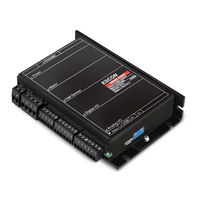
maxon motor ESCON 70/10 Hardware Reference Manual (40 pages)
Servo Controller
Brand:
maxon motor
| Category:
Controller
| Size: 2 MB
Table of Contents
T Cable of Contents 1 about 3
2
Table of Contents
2
About
3
About this Document
3
Table 1-1 Notation Used
3
About the Device
4
Table 1-2 Symbols & Signs
4
Table 1-3 Brand Names and Trademark Owners
4
About the Safety Precautions
5
Specifications
7
Technical Data
7
Figure 2-1 Derating Output Current
8
Table 2-4 Technical Data
8
Figure 2-2 Dimensional Drawing [MM]
9
Standards
10
Table 2-5 Standards
10
Setup
11
Generally Applicable Rules
11
Determination of Power Supply
12
Connections
13
Figure 3-3 Power Plug J1
13
Table 3-6 Power Plug J1 - Pin Assignment
13
Table 3-7 Power Plug J1 - Specification & Accessories
13
Figure 3-4 Motor Plug J2
14
Table 3-8 Motor Plug J2 - Pin Assignment for Maxon DC Motor (Brushed)
14
Table 3-9 Motor Plug J2 - Pin Assignment for Maxon EC Motor (Brushless)
14
Table 3-10 Motor Plug J2 - Specification & Accessories
14
Figure 3-5 Hall Sensor Plug J3
15
Figure 3-6 Hall Sensor 1 Input Circuit (Analogously Valid also for Hall Sensors 2 & 3)
15
Table 3-11 Hall Sensor Plug J3 - Pin Assignment
15
Table 3-12 Hall Sensor Plug J3 - Specification & Accessories
15
Figure 3-7 Encoder Socket J4
16
Table 3-13 Encoder Socket J4 - Pin Assignment
16
Table 3-14 Encoder Socket J4 - Accessories
16
Figure 3-8 Encoder Input Circuit Ch a "Differential" (Analogously Valid also for Ch B)
17
Table 3-15 Encoder Cable
17
Figure 3-9 Encoder Input Circuit Ch a "Single-Ended" (Analogously Valid also for Ch B)
18
Figure 3-10 Digital I/Os Plug J5
19
Table 3-16 Digital I/Os Plug J5 - Pin Assignment & Cabling
19
Table 3-17 Digital I/Os Plug J5 - Specification & Accessories
19
Figure 3-11 Digin1 Circuit
20
Figure 3-12 Digin2 Circuit
20
Figure 3-13 Digin3 Circuit (Analogously Valid also for Digin4)
21
Figure 3-14 Digout3 Circuit (Analogously Valid also for Digout4)
21
Figure 3-15 Digout3 Wiring Examples (Analogously Valid also for Digout4)
22
Figure 3-16 Analog I/Os Plug J6
23
Table 3-18 Analog I/Os Plug J6 - Pin Assignment & Cabling
23
Table 3-19 Analog I/Os Plug J6 - Specification & Accessories
23
Figure 3-17 Anin1 Circuit (Analogously Valid also for Anin2)
24
Figure 3-18 Anout1 Circuit (Analogously Valid also for Anout2)
24
Figure 3-19 USB Socket J7
25
Table 3-20 USB Socket J7 - Pin Assignment & Cabling
25
Table 3-21 USB Type a - Micro B Cable
25
Potentiometers
26
Status Indicators
26
Figure 3-20 Potentiometers - Location & Adjustment Range
26
Figure 3-21 Leds - Location
26
Table 3-22 Leds - Interpretation of Condition
27
External Motor Chokes
28
Table 3-23 External Motor Chokes - Specification & Accessories
28
Wiring
29
Figure 4-22 Interfaces - Designations and Location
29
DC Motors
30
Figure 4-23 Maxon DC Motor (J2)
30
Figure 4-24 Maxon DC Motor with DC Tacho (J2)
31
Figure 4-25 Maxon DC Motor with Encoder (J2 / J4)
32
EC Motors
33
Figure 4-26 Maxon EC Motor with Hall Sensors (J2 / J3)
33
Figure 4-27 Maxon EC Motor with Hall Sensors & Encoder (J2 / J3 / J4)
34
Spare Parts
35
Table 5-24 Spare Parts List
35
L Fist of Igures
37
Advertisement
Advertisement
Related Products
Maxon Motor ESCON 50/5
Maxon Motor ESCON 36/3 EC
Maxon Motor EPOS2 24/2
Maxon Motor EPOS2 70/10
Maxon Motor EPOS2 P 24/5
Maxon Motor EPOS 70/10
Maxon Motor EPOS4 Compact 50/5 CAN
maxon motor EPOS 24/5
maxon motor EPOS2 24/5
maxon motor EPOS4 Module 24/1.5
Maxon Motor Categories
Controller
DC Drives
Amplifier
Engine
Control Unit
More Maxon Motor Manuals
Login
Sign In
OR
Sign in with Facebook
Sign in with Google
Upload manual
Upload from disk
Upload from URL