Sign In
Upload
Manuals
Brands
Manitowoc Manuals
Construction Equipment
MLC300
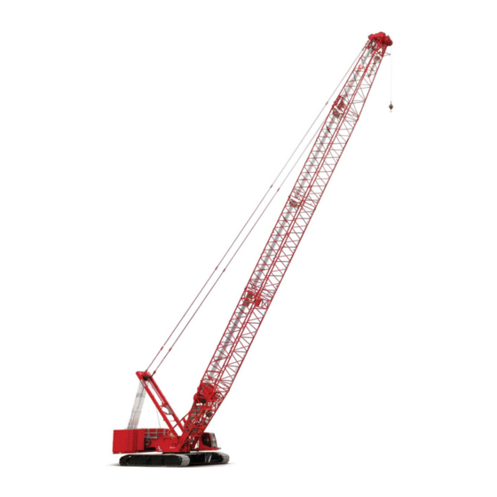
Manitowoc MLC300 Boom Crawler Crane Manuals
Manuals and User Guides for Manitowoc MLC300 Boom Crawler Crane. We have
8
Manitowoc MLC300 Boom Crawler Crane manuals available for free PDF download: Operator's Manual, Service And Maintenance Manual, Manual, Product Manual
Manitowoc MLC300 Service And Maintenance Manual (280 pages)
with Fixed Position Counterweight
Brand:
Manitowoc
| Category:
Construction Equipment
| Size: 57 MB
Table of Contents
See End of this Manual for Alphabetical Index
5
Table of Contents
5
Section 1
15
Continuous Innovation
15
Safety Messages
15
Safety Alert Symbol
15
Signal Words
15
Safe Maintenance Practices
16
Authorized Repair Personnel Only
16
Basic Crane Maintenance Safety
16
Before Starting a Maintenance Procedure
16
Precautions While Working on the Crane
16
Read this Manual
16
Chemical Handling Precautions
17
Fire Hazard Precautions
17
Maintain Structural Integrity of the Crane
17
Stored Energy Safety Precautions
17
Welding Hazard Avoidance
17
Protection of the Environment
18
Identification and Location of Major Components
18
Returning Crane to Service
18
Solenoid Valve Identification
22
Section 2 Hydraulic System
25
Section 2
25
Hydraulic System Overview
27
Hydraulic Pump Locations
27
Pumps 1 and 2
28
Pumps 3 and 4
29
Pump 5
30
Pump 6
30
Pump 7
31
Pump 8
31
Drum 1 Motor
34
Motor Locations
34
Drums 2, 3, 4, and 6 Motors
35
Travel Motors
36
Swing Motors
37
Rotating Bed Hydraulic Valves
38
Carbody Hydraulic Valves
39
Drum Pawl and Brake Valve Locations
40
Hydraulic System Maintenance
43
Disposing of Hydraulic Oil and Parts
43
Safety
43
Storing and Handling Oil
43
Storing and Handling Parts
43
Inspecting the Hydraulic System
44
Inspecting and Replacing Hydraulic Hoses
45
Periodic Inspection
45
Periodic Replacement
45
Replacing Hydraulic Filters
46
Replacing the Desiccant Breather Cartridge
46
Filter 1
47
Filter 2
47
Filter 4 and 5
48
Servicing Suction Strainers
49
Changing Hydraulic Oil
50
Servicing Pumps
50
Replacing Pressure Transducers
53
Replacing a Pressure Transducer
53
Testing a Pressure Transducer
53
Shop Procedures
54
Initial Hydraulic Oil Fill
54
Initial Hydraulic System Startup
55
Hydraulic Tests and Calibrations
56
Charge Pressure Test
56
Controls Calibration
56
Drum Speed Test
56
High Pressure Test
56
Pressure Sender Calibration
56
Swing Speed Test
56
Travel Speed Test
56
Disc Brake Operational Test
58
Free Fall Brake Operational Test
59
Accumulator Maintenance
60
Section 3 Electrical System
63
Electrical Drawings and Schematics
65
Electrical Power Sequence
65
Battery Power
65
Battery Power Disconnect
65
Crane Electrical Power Distribution
66
Crane Electrical System Ground Points
67
Cab Right Console Ground Points
67
General
67
Rotating Bed and Cab Mount /Arm Ground Points
68
Circuit Breakers, Fuses, and Relays
69
Inspect Electrical Components
72
Every Month or 200 Hours
72
Degradation Due to Severe Environment
72
CAN Bus Control System
73
CAN Bus System Overview
73
CAN Bus System Chart
74
Control Modules
75
Control Module Input/Output (I/O) Types
75
Control Module Naming Conventions
75
Crane Control Module (CCM)
75
Safety Control Module (SCM)
75
Input/Output-Large (IOL) Module
78
Input/Output-Small (IOS) Module
79
Control Module Devices
80
Motor Speed Sensors
80
Pressure Transducers
80
Alarms
81
Angle Sensors
81
Limit Switches-Dual Contact
81
Limit Switches-Single Contact
81
Load Pin Sensors
81
Solenoids
81
Foot Throttle
82
Fuel Level Sensor
82
Hand Throttle
82
Hydraulic Fluid Level Sensor
82
Pressure and Vacuum Switches
82
Pump Displacement Controls
82
Relays
82
Temperature Sensors
82
Travel and Free-Fall Brake Pedals
82
Control Module Test Voltages
83
Proximity Sensors
83
Pump and Motor Voltages and Currents
83
RCL Beacon
83
Wind Speed Indicators
83
Section 4 Boom
105
Section 4
105
General Maintenance
107
Boom and Luffing Jib Angle Indicator Calibration
107
Boom Stop Limit Switch
107
Automatic Boom Stop Overview
107
Maintenance
108
Adjusting the Automatic Boom Stop
109
Replacing the Boom Stop Limit Switch Actuator Rod
109
Automatic Luffing Jib Stop Adjustment and Maintenance
109
Boom Electrical Schematic
111
Luffing Jib Electrical Schematic
112
Strap Inspection and Maintenance
113
Cranes Not in Regular Use
113
Frequent Inspection
113
Identifying the Straps
113
Inspection
113
Periodic Inspection
113
Corrosion or Abrasion
114
Replacement Specifications
114
Flatness
115
Straightness
115
Elongated Hole
116
Storing the Straps
116
Strap Length
116
Inspection Checklist
117
Removing the Straps from Service
117
Lattice Section Inspection and Lacing Replacement
120
Section 5 Hoists
121
Section 5
121
General
125
Drum Identification
125
Drum 1-Main Hoist
126
Drum 1 Brake Operation
126
Drum 1 Brake Overview
126
Drum 1 Overview
126
Drum 1/3 Diverting
126
ON-PARK Operation
126
UN-PARK Operation
126
Drum 1 Hoisting Operation
127
Drum 1 Loop Flushing
127
Drum 1 Lowering Operation
127
Neutral
127
Drum 1 Hydraulic Schematic-Hoisting
128
Drum 1 Electrical Schematic
129
Drum 2-Auxiliary Front Hoist
130
Drum 2 Brake Operation
130
Drum 2 Brake Overview
130
Drum 2 Overview
130
ON-PARK Operation
130
UN-PARK Operation
130
Drum 2 Hoisting Operation
131
Drum 2 Loop Flushing
131
Drum 2 Lowering Operation
131
Neutral
131
Drum 2 Hydraulic Schematic-Hoisting
132
Drum 2 Electrical Schematic
133
Drum 3-Auxiliary Rear Hoist
134
Drum 1/3 Diverting
134
Drum 3 Brake Operation
134
Drum 3 Brake Overview
134
Drum 3 Overview
134
ON-PARK Operation
134
UN-PARK Operation
134
Drum 3 Hoisting Operation
135
Drum 3 Loop Flushing
135
Drum 3 Lowering Operation
135
Neutral
135
Drum 3 Hydraulic Schematic-Hoisting
136
Drum 3 Electrical Schematic
137
Drum 4-Boom Hoist
138
Drum 4 Brake Operation
138
Drum 4 Brake Overview
138
Drum 4 Overview
138
Joystick Control
138
ON-PARK Operation
138
UN-PARK Operation
138
Drum 4 Hoisting Operation
139
Drum 4 Pawl Control
139
Pawl Disengagement
139
Pawl Engagement
139
Drum 4 Lowering Operation
140
Neutral
140
Brake Defeat Valve
141
Drum 4 Cavitation Protection
141
Drum 4 Motor Case Protection
141
High Pressure Protection
141
Drum 4 Hydraulic Schematic-Hoisting
142
Drum 4 Hydraulic Schematic-Lowering
143
Drum 4 Electrical Schematic
144
Drum 6-Auxiliary Hoist
145
Drum 6 Brake Operation
145
Drum 6 Brake Overview
145
Drum 6 Overview
145
Joystick Control
145
ON-PARK Operation
145
UN-PARK Operation
145
Drum 6 Hoisting Operation
146
Drum 6 Pawl Control
146
Pawl Disengagement
146
Brake Defeat Valve
147
Drum 6 Cavitation Protection
147
Drum 6 Lowering Operation
147
Drum 6 Motor Case Protection
147
High Pressure Protection
147
Neutral
147
Drum 6 Hydraulic Schematic-Hoisting
148
Drum 6 Hydraulic Schematic-Lowering
149
Drum 6 Electrical Schematic
150
Drum Gearbox Oil Change
151
Every 6 Months or 1,000 Hours
151
Gear Oil Specifications
151
Initial Operation
151
Monthly or 200 Hours
151
Oil Analysis
151
Periodic Maintenance
151
Quick-Drain Valve
151
Oil Change Procedure
152
Drum 4 Pawl
154
Maintenance
154
Operation
154
Spring Adjustment
154
Limit Switch Adjustment
154
Daily
154
Drum 4 Parked
154
Drum 4 Un-Parked
154
Weekly
154
Daily
156
Drum 6 Parked
156
Drum 6 Pawl
156
Drum 6 Un-Parked
156
Limit Switch Adjustment
156
Maintenance
156
Operation
156
Spring Adjustment
156
Weekly
156
Drum 1 Minimum Bail Limit
158
Limit Switch Adjustment
158
Pre-Adjustment
158
Spring Adjustment
158
Drum 2/3 Minimum Bail Limit (Non-Free Fall Drum)
160
Limit Switch Adjustment
160
Pre-Adjustment
160
Drum 2/3 Minimum Bail Limit (Free Fall Drum)
161
Limit Switch Adjustment
161
Pre-Adjustment
161
Drum 6 Minimum Bail Limit
162
Limit Switch Adjustment
162
Pre-Adjustment
162
Spring Adjustment
162
Speed Sensor-Hoist Motors
163
Replacement
163
Block Level
164
Drum 2 Block Level Proximity Sensors
164
Drum 3 Block Level Proximity Sensors
164
Proximity Sensor Operation
164
Proximity Sensor Replacement and Adjustment
164
Weekly Maintenance
164
Block-Up Limit Installation and Adjustment
166
General
166
Removing the Luffing Jib
166
Two-Blocking Definition
166
Adjustment
168
Maintenance
168
Wire Rope Inspection and Replacement
170
Maintain a Wire Rope Condition Report
170
Required Inspection Intervals
170
Wire Rope Care and Replacement Guidelines
170
Wire Rope Lubrication
170
Daily Inspection
171
Determining the Frequency of Inspection
172
Periodic Comprehensive Inspection
172
Reduction in the Rope Diameter
172
Replacement Criteria
172
Broken Rope Wires
173
Distributing Wire Rope Wear
174
Rope that Has Been Idle a Month or more
174
Sheave, Roller, and Drum Inspection
174
Load Block and Hook-And-Weight Ball Inspection
177
Daily Inspection
177
Yearly Inspection
179
Section 6 Swing System
181
General
183
Swing Brake Operation
183
Park Switch Control
183
Holding Brake Switch Control
183
Swing System Overview
183
Swing Operation
184
Swing Pump Control
184
Swing Left
184
Cross Port Orifice
184
Swing Right
184
Coasting
184
Swing Alarm
184
Swing Left Hydraulic Schematic
185
Swing Right Hydraulic Schematic
186
Swing Electrical Schematic
187
Swing Brake Manual Release
188
Swing Gearbox Oil Change
189
Every 6 Months or 1,000 Hours
189
Gear Oil Specifications
189
Initial Operation
189
Monthly or Every 200 Hours
189
Oil Analysis
189
Periodic Maintenance
189
Quick-Drain Valve
189
Oil Change Procedure
190
Swing Motor Speed Sensor
191
Speed Sensor Adjustment
191
Speed Sensor Replacement
191
Weekly Periodic Maintenance
191
Advertisement
Manitowoc MLC300 Operator's Manual (332 pages)
Brand:
Manitowoc
| Category:
Construction Equipment
| Size: 64 MB
Table of Contents
Table of Contents
5
Section 1
13
Crane Data
13
Crane Weights
13
Outline Dimensions
13
Change of Ownership Registration
13
Manitowoc Dealer
13
Crane/Attachment Identification
13
Crane Orientation
13
Identification and Location of Components
15
English and Metric Conversions
18
Direct Conversion
18
Inverse Conversion
18
Section 2
21
Continuous Innovation
23
Nameplates and Decals
23
Safety Messages
23
General
23
Safety Alert Symbol
23
Signal Words
23
Symbol Identification
23
Safety and Information Signs
25
Maintaining Signs
25
Ordering Signs
25
Crane Access Points
28
General
28
Getting on or off Crane
28
Personal Fall-Protection
29
Operator Manual/Capacity Chart Storage
30
General
30
Storing Manuals
30
Safe Operating Practices
31
General
31
Read Operator Manual
31
Operator Qualifications
31
Operator Conduct
31
Handling Load
33
Size of Load
33
Attaching Load
33
Lifting/Moving Load
34
Multiple Load Line Operation
35
Signals
36
Holding Load
36
Safety Devices
37
Operational Aids
37
Category 1 Operational Aids
37
Category 2 Operational Aids
38
Assembling, Disassembling, or Operating Crane Near Electric Power and Transmission Lines
39
Electrocution Hazard
39
Set-Up and Operation
39
Electrocution Hazard Devices
40
Electrical Contact
40
Refueling
41
Fire Extinguishers
41
Accidents
41
Safe Maintenance
41
Maintenance Instructions
41
Safe Maintenance Practices
41
Environmental Protection
43
Boom Disassembly Safety
45
General
45
Location
45
Pin Removal
45
Disassembly Precaution
45
Personnel Handling Policy
46
Pedestal/Barge Mounted Cranes
47
Pedestal Mounted Crane
48
Barge Mounted Crane
48
Definition
48
Examples
48
Capacity Charts for Barge Mounted Crane
49
Shock Loading Caused by Barge Dynamics
49
Operation on Barge
49
Barge Mount Definitions
50
Inspection of Barge-Mounted Crane
50
Transporting Crane on Barge
50
Section 3
51
Standard Hand Signals for Controlling Crane Operations
54
Symbols Used on Control Consoles
56
Symbols Used on Remote Control
59
Operating Controls
62
Left Console
66
Right Console
68
Seat Controls
80
Climate Control Keypad
81
Other Operator Aids
82
Boom Angle Indicator
82
Crane Capacity Beacons
82
Upperworks Level
82
Crane Cameras
84
Crane Camera Monitor
85
Motion Warning Lights and Alarms
86
Service Lights
88
Remote Control Activation
90
Remote Control Operation
92
Operating Limits Identification and Operation
98
Bypassing Limits in Luffing Jib Setup Mode
104
Resetting Luffing Jib Limits
105
Drum and Control Handle Identification
106
Right Cab Window Operation
109
Closing Window
109
Opening Window for Ventilation
109
Operator Cab Emergency Exit
109
Cab Door Adjustment
109
Cab Tilt Stop Pins Installation
109
Cab Tilt Speed Adjustment
109
Ladder Installation (Past)
111
Installing Ladder
111
Storing Ladder
111
Using Ladder (Working Position)
111
Removing Ladder
111
Ladder Installation (Current)
113
Installing Ladder
113
Storing Ladder
113
Using Ladder (Working Position)
113
Removing Ladder
113
Operating in Wind
114
Crawler Blocking
114
Intermediate Suspension
114
Preparing Crane for Operation
115
Startup Procedure
115
Operating Procedures
119
VPC Operation
119
Boom Hoist Operation
120
Luffing Hoist Operation
121
Swing Operation
122
Load Drum Operation (Without Free Fall or with Free Fall Disabled)
125
Load Drum Operation (with Free Fall Enabled)
127
Free Fall Brake Pedal Hydraulic Pressure Test
129
Free Fall Brake Operational Test
129
Clamshell Operation
130
Preparing for Clamshell Operation
130
Clamshell Operation in Full-Power
130
Travel Operation
132
Shutdown Procedure or Leaving the Crane Unattended
134
Changing Counterweight with Boom/Jib in Air
135
Vpc
135
Vpc-Max
135
Cold Weather Operation
137
Crane Limitations
137
Wire Rope
137
Cold Weather Starting Aid
137
Cooling System
137
Batteries
137
Engine Oil, Gear Oil, and Hydraulic Oil
137
Cold Weather Heater Package
139
Turning Heaters on
139
Turning Heaters off
139
AC Operation
141
Installing APU
141
Turning on AC Powered Components
141
Turning off AC Powered Components
141
Removing APU
141
Manitowoc MLC300 Operator's Manual (256 pages)
Brand:
Manitowoc
| Category:
Construction Equipment
| Size: 53 MB
Table of Contents
Table of Contents
5
Section 1
13
Crane Data
13
Crane Weights
13
Outline Dimensions
13
Change of Ownership Registration
13
Manitowoc Dealer
13
Crane/Attachment Identification
13
Crane Orientation
13
Identification and Location of Components
14
English and Metric Conversions
16
Direct Conversion
16
Inverse Conversion
16
Section 2
19
Continuous Innovation
21
Nameplates and Decals
21
Safety Messages
21
General
21
Safety Alert Symbol
21
Signal Words
21
Symbol Identification
21
Safety and Information Signs
23
Maintaining Signs
23
Ordering Signs
23
Crane Access Points
24
General
24
Getting on or off Crane
24
Personal Fall-Protection
29
Operator Manual/Capacity Chart Storage
30
General
30
Storing Manuals
30
Safe Operating Practices
31
General
31
Read Operator Manual
31
Operator Qualifications
31
Operator Conduct
31
Handling Load
33
Size of Load
33
Attaching Load
33
Lifting/Moving Load
34
Multiple Load Line Operation
35
Signals
36
Holding Load
36
Safety Devices
37
Operational Aids
37
Category 1 Operational Aids
37
Category 2 Operational Aids
38
Assembling, Disassembling, or Operating Crane Near Electric Power and Transmission Lines
39
Electrocution Hazard
39
Set-Up and Operation
39
Electrocution Hazard Devices
40
Electrical Contact
40
Refueling
41
Fire Extinguishers
41
Accidents
41
Safe Maintenance
41
Maintenance Instructions
41
Safe Maintenance Practices
41
Environmental Protection
43
Boom Disassembly Safety
45
General
45
Location
45
Pin Removal
45
Disassembly Precaution
45
Personnel Handling Policy
46
Pedestal/Barge Mounted Cranes
47
Pedestal Mounted Crane
48
Barge Mounted Crane
48
Definition
48
Examples
48
Capacity Charts for Barge Mounted Crane
49
Shock Loading Caused by Barge Dynamics
49
Operation on Barge
49
Barge Mount Definitions
50
Inspection of Barge-Mounted Crane
50
Transporting Crane on Barge
50
Section 3
51
Standard Hand Signals for Controlling Crane Operations
54
Operating Controls and Procedures
55
Operating Precautions
55
Auxiliary Frame Assembly Operating Positions
57
Section 4
63
General Set-Up and Installation
63
General Safety
63
Crane Orientation
64
Boom and Jib Assembly Drawings
64
Accessing Parts
64
Personal Fall-Protection
64
Handling Components
64
Assist Crane Requirements
65
Crane Weights and Shipping Data
65
Parts Box
65
Lifting Slings and Shackles
65
Retaining Connecting Pins
65
Remote Control
68
Activating Remote Control
69
Starting Engine with Remote Control
69
Crane and VPC-MAX Setup
69
Pin and Connecting Hole Cleanliness
70
Hose and Cable Cleanliness
70
Hydraulic Hose Identification
70
Connecting/Disconnecting Hydraulic Hoses and Electric Cables
70
Tightening Hydraulic Couplers
70
Operating Conditions During Assembly and Disassembly
73
Installing VPC-MAX Beam and Trolley
75
Prepare Crane
75
Check VPC Trolley Travel Limits and Calibration
75
Prepare VPC Trolley
77
Store Exhaust Shield on Crane
77
Remove VPC-MAX Beam from Trailer
79
Unfold VPC-MAX Beam
81
Remove Handrails from VPC-MAX Beam
83
Attach VPC-MAX Beam to VPC Trolley
85
Connect VPC-MAX Beam-To-VPC Trolley Electric Cable
89
Connect VPC-MAX Beam-To-VPC Trolley Hydraulic Hoses
89
Hook VPC-MAX Beam to Rotating Bed
91
Remove Counterweight Tray from Trailer
93
Prepare Counterweight Tray
93
Remove VPC-MAX Trolley from Trailer
95
Adjust VPC-MAX Trolley Wear Pads
95
Adjust VPC-MAX Trolley Scrapers
95
Install Trolley Installation Guides
97
Attach VPC-MAX Trolley to Counterweight Tray
99
Install VPC-MAX Trolley and Counterweight Tray
101
Connect VPC-MAX Energy Chain to VPC-MAX Trolley
103
Connect VPC-MAX Trolley Electric Cables
103
Connect VPC-MAX Trolley Hydraulic Hoses
103
Check VPC-MAX Trolley Travel Limits and Calibration
105
Install Auxiliary Frame Assembly
105
Install Handrails
107
Install VPC-MAX Beam Ladder
109
Position Counterweight Tray in Minimum Position
111
Calibrate Position of VPC-MAX Trolley
111
Installing VPC-MAX #503 Fixed Mast
113
Remove Fixed Mast Butt and Top Assembly from Trailer
113
Verify Mast Stop Accumulator Pressure
113
Raise Mast Stops
113
Connect Fixed Mast Butt and Top Assembly to Crane
115
Connect Fixed Mast Hydraulic Hoses
117
Connect Fixed Mast Electric Cable
117
Connect Fixed Mast Camera Cables
117
Disconnect Fixed Mast Top from Fixed Mast Butt
119
Assemble and Install Fixed Mast Inserts
121
Store Handling Pendants
123
Store Self-Erect Cylinder
123
Connect Straps at Mast Top
125
Test Mast Stop Limit Switch
125
Connect Straps at Mast Inserts
127
Connect Straps at Mast Butt
129
Connect Live Mast Straps to Fixed Mast
130
Lower Live Mast Assist Arms
131
Configure Fixed Mast in RCL/RCI Display
131
Fixed Mast Raising Methods
133
Target Tension During Fixed Mast Raising and Lowering
133
Raising Fixed Mast - Preferred Method with Boom Holdback
135
Disconnect Boom Hoist Equalizer from Mast Top
135
Raise Fixed Mast to Boom Rigging Position
135
Install Counterweight Boxes
137
Assemble Partial Boom
137
Install Partial Boom
139
Assemble Remaining Boom Sections
141
Connect Boom Straps
141
Connect Boom Sections
143
Finish Assembling Boom
143
Connect Equalizer Links to Boom Straps
145
Raise Fixed Mast to Operating Position
145
Adjust Fixed Mast and Beam Position
147
Raise Boom
147
Raising Fixed Mast - Alternate Method with Anchored Holdback
148
Disconnect Boom Hoist Equalizer from Mast Top
148
Anchor Boom Hoist Equalizer to Holdback
149
Raise Fixed Mast
149
Install Boom
153
Install Boom Hoist Equalizer on Equalizer Rails
153
Connect Equalizer Links to Boom Straps
153
Install Counterweight Boxes
153
Adjust Fixed Mast and Beam Position
153
Raise Boom
153
Raising Boom
154
Pre-Raising Checks
154
Boom Raising Procedure
155
Auxiliary Frame Operating Positions
157
Shipping Crane Components
159
Lowering Boom
159
Fixed Mast Lowering Methods
161
Lowering Fixed Mast - Preferred Method with Boom Holdback
161
Disconnect Counterweight Straps
161
Lower Fixed Mast to Disassembly Position
163
Disconnect Equalizer Links from Boom Straps
163
Prepare Boom for Removal
163
Disconnect Boom Sections
165
Disconnect Boom Straps
167
Disassemble Boom Sections
167
Remove Partial Boom
169
Disassemble Partial Boom
171
Remove Counterweight Boxes
171
Lower Fixed Mast to Disassembly Position
171
Connect Boom Hoist Equalizer to Mast Top
171
Lowering Fixed Mast - Alternate Method with Anchored Holdback
173
Remove Counterweight Boxes
173
Remove Boom Hoist Equalizer from Equalizer Rails
173
Remove Boom
173
Anchor Boom Hoist Equalizer to Holdback
175
Disconnect Counterweight Straps
175
Lower Fixed Mast
175
Connect Boom Hoist Equalizer to Mast Top
175
Removing VPC-MAX #503 Fixed Mast
177
Raise Live Mast Assist Arms
177
Configure Live Mast in RCL/RCI
177
Disconnect Live Mast Straps from Fixed Mast
177
Disconnect and Store Straps at Mast Top
179
Disconnect and Store Straps at Mast Inserts
181
Disconnect and Store Straps at Mast Butt
183
Deploy Self-Erect Cylinder
185
Connect Handling Pendants
185
Store Load Lines
187
Remove Fixed Mast Top
187
Remove and Disassemble Fixed Mast Inserts
187
Connect Fixed Mast Top to Fixed Mast Butt
189
Disconnect Fixed Mast Hydraulic Hoses
191
Disconnect Fixed Mast Electric Cable
191
Disconnect Fixed Mast Camera Cables
191
Disconnect Fixed Mast Butt and Top Assembly from Crane
193
Lower Mast Stops
195
Install Fixed Mast Butt and Top Assembly on Trailer
195
Removing VPC-MAX Beam and Trolley
197
Remove Handrails
197
Remove Auxiliary Frame Assembly
199
Install Hose/Cable Storage Brackets
201
Position VPC-MAX Trolley at End of Beam
203
Attach Lifting Slings to Counterweight Tray
203
Install Trolley Installation Guides
205
Disengage Trolley Drive Pinions from Gear Racks
207
Disconnect VPC-MAX Trolley Hydraulic Hoses
209
Disconnect VPC-MAX Trolley Electric Cables
209
Disconnect VPC-MAX Energy Chain from VPC-MAX Trolley
209
Remove VPC-MAX Trolley and Counterweight Tray
211
Remove VPC-MAX Trolley from Counterweight Tray
213
Install Counterweight Tray on Trailer
213
Unhook VPC-MAX Beam from Rotating Bed
215
Disconnect VPC-MAX Beam-To-VPC Trolley Electric Cable
217
Disconnect VPC-MAX Beam-To-VPC Trolley Hydraulic Hoses
217
Disconnect VPC-MAX Beam from VPC Trolley
219
Store Handrails in VPC-MAX Beam
221
Fold VPC-MAX Beam for Shipping
223
Install VPC-MAX Beam on a Trailer
225
Complete Disassembly
225
Wire Rope Installation
225
Advertisement
Manitowoc MLC300 Operator's Manual (194 pages)
Luffing Jib
Brand:
Manitowoc
| Category:
Construction Equipment
| Size: 37 MB
Table of Contents
Table of Contents
5
Section 1
11
Crane Data
11
Crane Weights
11
Outline Dimensions
11
Change of Ownership Registration
11
Manitowoc Dealer
11
Crane/Attachment Identification
11
Crane Orientation
11
Identification and Location of Components
12
English and Metric Conversions
14
Direct Conversion
14
Inverse Conversion
14
Section 2
17
Continuous Innovation
19
Nameplates and Decals
19
Safety Messages
19
General
19
Safety Alert Symbol
19
Signal Words
19
Symbol Identification
19
Safety and Information Signs
21
Maintaining Signs
21
Ordering Signs
21
Crane Access Points
24
General
24
Getting on or off Crane
24
Personal Fall-Protection
25
Operator Manual/Capacity Chart Storage
26
General
26
Storing Manuals
26
Safe Operating Practices
27
General
27
Read Operator Manual
27
Operator Qualifications
27
Operator Conduct
27
Handling Load
29
Size of Load
29
Attaching Load
29
Lifting/Moving Load
30
Multiple Load Line Operation
31
Signals
32
Holding Load
32
Safety Devices
33
Operational Aids
33
Category 1 Operational Aids
33
Category 2 Operational Aids
34
Assembling, Disassembling, or Operating Crane Near Electric Power and Transmission Lines
35
Electrocution Hazard
35
Set-Up and Operation
35
Electrocution Hazard Devices
36
Electrical Contact
36
Refueling
37
Fire Extinguishers
37
Accidents
37
Safe Maintenance
37
Maintenance Instructions
37
Safe Maintenance Practices
37
Environmental Protection
39
Boom Disassembly Safety
41
General
41
Location
41
Pin Removal
41
Disassembly Precaution
41
Personnel Handling Policy
42
Pedestal/Barge Mounted Cranes
43
Pedestal Mounted Crane
44
Barge Mounted Crane
44
Definition
44
Examples
44
Capacity Charts for Barge Mounted Crane
45
Shock Loading Caused by Barge Dynamics
45
Operation on Barge
45
Barge Mount Definitions
46
Inspection of Barge-Mounted Crane
46
Transporting Crane on Barge
46
Section 3
47
Standard Hand Signals for Controlling Crane Operations
50
General Operation
52
Luffing Jib Operating Controls
53
Rated Capacity Limiter/Indicator (RCL/RCI) Display
53
Main Display
53
Boom Angle
53
Luffing Jib Angle
53
Wind Speed
53
Crane Levelness
53
Limit Bypass Switch
54
Drum 4 (Boom Hoist) Park Switch
54
Drum 6 (Luffing Hoist) Park Switch
54
Boom Hoist Control
54
Luffing Hoist and Swing Control
54
Wind Speed Transmitter
54
10 - Mechanical Boom Angle Indicator
54
11 - Crane Level
54
Boom-To-Luffing Jib Angle
54
Operating Limits Identification and Operation
55
Bypassing Limits in Luffing Jib Setup Mode
60
Resetting Luffing Jib Limits
61
Drum and Control Handle Identification
62
Operating Precautions
63
Leaving Crane Unattended
63
Wind Conditions
64
Manitowoc MLC300 Manual (211 pages)
Brand:
Manitowoc
| Category:
Construction Equipment
| Size: 7 MB
Manitowoc MLC300 Manual (36 pages)
Brand:
Manitowoc
| Category:
Construction Equipment
| Size: 9 MB
Table of Contents
Table of Contents
1
Lubrication Symbols
2
General Lubrication
2
Lubrication Intervals
2
Over-Lubrication
3
Lubrication Tips
3
Water in Hydraulic Oil
3
Oil Can Points
3
Wire Rope Lubrication
3
Cylinder Rod Lubrication
4
General
4
Protecting Cylinder Rods
4
Hydraulic Quick Disconnect Lubrication
4
Environmental Protection
5
Reference Instructions
5
Cranelube
5
Lubrication Points
5
Approved Lubricants for Normal Operation
6
Grease
6
Open Gear Oil
6
Gear Oil
6
Hydraulic Oil
6
Hydraulic Filter Replacement
7
Approved Lubricants for Arctic Operation
8
Approved Lubricants for High Temperature Operation
9
Fluid Capacities
10
Upperworks and Lowerworks Lubrication
12
Prior to Use When the Crane Is Assembled
18
Every 8 Hours of Operation or Daily (Whichever Comes First)
18
Every 8 Hours of Operation or Daily Continued
19
Every 40 Hours of Operation or Weekly (Whichever Comes First)
20
After First 200 Hours of Operation
21
Every 200 Hours of Operation or Monthly (Whichever Comes First)
22
Every 1000 Hours of Operation or Semiannually (Whichever Comes First)
23
Boom Rigging Lubrication
24
Luffing Jib Lubrication
26
VPC™ Lubrication
28
VPC-Max™ Lubrication
30
Automatic Lubrication System
34
Operation
34
Daily Inspection
34
Automatic Lubrication System Troubleshooting
35
Manitowoc MLC300 Manual (65 pages)
Brand:
Manitowoc
| Category:
Construction Equipment
| Size: 2 MB
Manitowoc MLC300 Product Manual (36 pages)
Brand:
Manitowoc
| Category:
Construction Equipment
| Size: 13 MB
Table of Contents
Table of Contents
5
Outline Dimensions
9
Transport Data
13
Assembly
14
Performance Data
16
Boom Combinations
19
Main Boom Range / Load Charts
21
Manitowoc Crane Care
34
Advertisement
Related Products
Manitowoc MLC165
Manitowoc MLC165-1
Manitowoc MLC650
Manitowoc MLC90A-1
Manitowoc MLC100-1
Manitowoc MLC80A-1
Manitowoc MLC100A-1
Manitowoc MLC150-1
Manitowoc Multiplex MS-8-1LH
Manitowoc Multiplex MS000A04
Manitowoc Categories
Ice Maker
Construction Equipment
Accessories
Commercial Food Equipment
Dispenser
More Manitowoc Manuals
Login
Sign In
OR
Sign in with Facebook
Sign in with Google
Upload manual
Upload from disk
Upload from URL