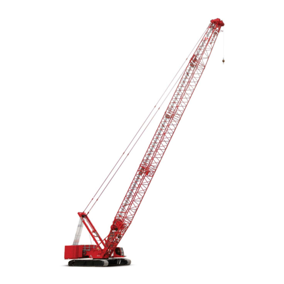
Manitowoc MLC300 Manual
Hide thumbs
Also See for MLC300:
- Operator's manual (332 pages) ,
- Service and maintenance manual (280 pages) ,
- Manual (211 pages)
Advertisement
Quick Links
Liftcrane Luffing Jib Capacities
Luffing Jib No. LJ11:500-501 on
Boom No. B65:505-500
with Mast No. M11:503
135 100 kg VPC (Variable Position Counterweight)
360 Degree Rating
LIFTING CAPACITIES: Lifting capacities for
various boom lengths, boom angles, luffing jib
lengths, and luffing jib operating radii are for freely
suspended loads and may be based on percent of static
tipping or strength of structural components. Capacities must
be reduced by applicable deducts.
Upper luffing jib point capacity for liftcrane service with single
part whip line is 16 600 kg or 33 300 kg with two part whip
line. In all cases, upper luffing jib point capacities cannot
exceed those listed for main luffing jib capacity.
Weight of all load blocks, hooks, weight ball, slings, hoist
lines, etc., beneath boom and luffing jib point sheaves is
considered part of load. Boom and luffing jib are not to be
lowered beyond radii where combined weights are greater
than rated capacity. Where no capacity is shown, operation
is not intended or approved.
LUFFING
JIB
BACKWARD
indicated by (b) require 2 270 kg minimum weight suspended
beneath luffing jib point, (c) require 4 540 kg minimum
weight, and (d) require 9 080 kg minimum weight. Caution:
Do not luff into areas indicated by (b), (c), or (d) without
required minimum weight. Luffing jib may not luff down and
luffing hoist wire rope may go slack. Luffing hoist wire rope
may overhaul luffing jib and cause wire rope damage or
failure.
OPERATING CONDITIONS: Machine to operate on a firm,
level, and uniformly supporting surface. Supporting surface
and bearing turntable are to be level within a tolerance of
13 mm in 3 m. During operation, boom must be maintained
at one of the selected angles shown in chart. Refer to Luffing
Jib Rigging No. 84050217, Mast Rigging No. 84045340,
Wire Rope Specifications chart No. 9668-A, Counterweight
Arrangements chart No. 9345-A, Luffing Jib Raising
Procedure chart No. 9665-AM, and Wind Conditions chart
No. 9667-A. Crane operator judgment must be used to allow
for dynamic load effects of swinging, hoisting or lowering,
travel, wind conditions, as well as adverse operating
conditions and physical machine depreciation. Refer to the
Operator Manual for operating guidelines.
Manitowoc Cranes
Manitowoc, Wisconsin 54220 U.S.A.
ASME B30.5
STABILITY: Capacities
MACHINE TRAVEL: Machine to travel on a firm, level, and
uniformly supporting surface. Boom and luffing jib must be
within angle range shown in capacity chart. Refer to
Maximum Allowable Travel Specifications chart No. 9666-A.
OPERATING
RADIUS: Operating
horizontal distance from axis of rotation to center of
vertical hoist line or load block.
BOOM ANGLE: Boom angle in degrees (°) is
angle between horizontal and centerline of boom
butt and inserts.
LUFFING JIB ANGLE: Luffing jib angle in
degrees (°) is angle between horizontal and
centerline of luffing jib butt and inserts, and is an
indication of operating radius. In all cases, operating
radius shall govern capacity.
LUFFING JIB POINT ELEVATION: Luffing jib
point elevation is vertical distance from ground level
to centerline of luffing jib point shaft.
MACHINE EQUIPMENT: Machine equipped with VPC-MAX,
9 700 mm
crawlers,
1 219 mm
9 144 mm live mast, 30,0 m mast, 10 part boom hoist
reeving, boom support straps, 14 part luffing jib hoist reeving,
luffing jib and backstay support straps, and 135 100 kg VPC.
Select counterweight position from Luffing Jib Raising
Procedure chart No. 9665-AM that will allow raising and
lowering of boom and luffing jib length. Counterweight
position selection may be changed with luffing jib on ground
or while luffing jib is within operating range of capacity chart.
MLC300
VPC-MAX
SERIES 1
radius
is
or
1 524 mm
treads,
9660-AM, 2019-03-27
1/65
Advertisement

Subscribe to Our Youtube Channel
Related Manuals for Manitowoc MLC300


Summary of Contents for Manitowoc MLC300
- Page 1 No. 9667-A. Crane operator judgment must be used to allow for dynamic load effects of swinging, hoisting or lowering, travel, wind conditions, as well as adverse operating conditions and physical machine depreciation. Refer to the Operator Manual for operating guidelines. Manitowoc Cranes 9660-AM, 2019-03-27 Manitowoc, Wisconsin 54220 U.S.A. 1/65...
-
Page 2: Explanation Of Symbols
VPC-MAX S-1 Explanation of Symbols Luffing Jib No. LJ11:500-501 LJ11 Boom No. B65:505-500 VPC (Variable Position Counterweight) 360 Degree Rating 360° Boom Length Luffing Jib Length Boom Angle (see page 1) 9660-AM, 2019-03-27 Manitowoc Cranes 2/65 Manitowoc, Wisconsin 54220 U.S.A. - Page 3 Explanation of Symbols (continued) Operating Radius (see page 1) Luffing Jib Angle (see page 1) Luffing Jib Elevation (see page 1) Counterweight Position from Axis of Rotation Lifting Capacities (see page 1) Manitowoc Cranes 9660-AM, 2019-03-27 Manitowoc, Wisconsin 54220 U.S.A. 3/65...
- Page 4 74 000 33,8 68,4 62 800 79 000 32,0 34,0 23,1 64,3 58 100 73 300 34,0 36,0 36,0 38,0 38,0 40,0 40,0 42,0 42,0 44,0 44,0 46,0 46,0 48,0 48,0 9660-AM, 2019-03-27 Manitowoc Cranes 4/65 Manitowoc, Wisconsin 54220 U.S.A.
- Page 5 42,0 44,0 16,3 59,1 36 600 48 000 40,1 66,1 33 900 45 600 44,0 46,0 31,5 63,1 31 900 43 100 46,0 48,0 19,5 58,5 30 000 40 800 48,0 Manitowoc Cranes 9660-AM, 2019-03-27 Manitowoc, Wisconsin 54220 U.S.A. 5/65...
- Page 6 56 700 30,0 70,0 50 300 63 800 38,0 40,0 20,4 65,4 47 100 59 600 40,0 42,0 42,0 44,0 44,0 46,0 46,0 48,0 48,0 50,0 50,0 52,0 52,0 54,0 54,0 9660-AM, 2019-03-27 Manitowoc Cranes 6/65 Manitowoc, Wisconsin 54220 U.S.A.
- Page 7 48,0 50,0 14,4 59,8 30 500 40 500 35,6 68,0 27 800 38 300 50,0 52,0 28,0 64,6 26 300 36 400 52,0 54,0 17,3 59,4 24 800 34 600 54,0 Manitowoc Cranes 9660-AM, 2019-03-27 Manitowoc, Wisconsin 54220 U.S.A. 7/65...
- Page 8 44 800 27,2 71,4 40 900 52 300 44,0 46,0 18,5 66,3 38 500 48 800 46,0 48,0 48,0 50,0 50,0 52,0 52,0 54,0 54,0 56,0 56,0 58,0 58,0 60,0 60,0 9660-AM, 2019-03-27 Manitowoc Cranes 8/65 Manitowoc, Wisconsin 54220 U.S.A.
- Page 9 54,0 56,0 13,0 60,4 24 600 33 900 32,3 69,8 22 000 31 900 56,0 58,0 25,4 65,9 20 800 30 400 58,0 60,0 15,7 60,2 19 600 29 000 60,0 Manitowoc Cranes 9660-AM, 2019-03-27 Manitowoc, Wisconsin 54220 U.S.A. 9/65...
- Page 10 35 700 25,1 72,7 34 200 39 800 50,0 52,0 17,1 67,2 32 400 37 400 52,0 54,0 54,0 56,0 56,0 58,0 58,0 60,0 60,0 62,0 62,0 64,0 64,0 66,0 66,0 9660-AM, 2019-03-27 Manitowoc Cranes 10/65 Manitowoc, Wisconsin 54220 U.S.A.
- Page 11 60,0 62,0 12,0 61,0 20 500 29 200 29,7 71,4 18 100 27 300 62,0 64,0 23,4 67,2 17 100 26 100 64,0 66,0 14,4 60,9 16 100 24 900 66,0 Manitowoc Cranes 9660-AM, 2019-03-27 Manitowoc, Wisconsin 54220 U.S.A. 11/65...
- Page 12 28 600 29 400 23,4 74,0 28 300 36 500 56,0 58,0 15,9 68,0 26 900 34 000 58,0 60,0 60,0 62,0 62,0 64,0 64,0 66,0 66,0 68,0 68,0 70,0 70,0 9660-AM, 2019-03-27 Manitowoc Cranes 12/65 Manitowoc, Wisconsin 54220 U.S.A.
- Page 13 25 700 32,6 76,4 14 600 23 800 66,0 68,0 11,2 61,6 16 000 24 500 27,7 72,9 13 700 22 700 68,0 70,0 21,8 68,3 12 900 21 700 70,0 Manitowoc Cranes 9660-AM, 2019-03-27 Manitowoc, Wisconsin 54220 U.S.A. 13/65...
- Page 14 18 100 18 100 22,0 75,1 20 200 20 200 62,0 64,0 14,9 68,8 18 800 18 800 64,0 66,0 66,0 68,0 68,0 70,0 70,0 72,0 72,0 74,0 74,0 76,0 76,0 9660-AM, 2019-03-27 Manitowoc Cranes 14/65 Manitowoc, Wisconsin 54220 U.S.A.
- Page 15 19 900 30,7 78,1 11 600 20 400 72,0 74,0 10,5 62,2 13 000 18 500 26,1 74,2 10 900 19 500 74,0 76,0 20,5 69,4 10 200 18 700 76,0 Manitowoc Cranes 9660-AM, 2019-03-27 Manitowoc, Wisconsin 54220 U.S.A. 15/65...
- Page 16 18 900 19 100 20,8 76,2 19 100 24 300 68,0 70,0 14,1 69,5 18 100 22 600 70,0 72,0 72,0 74,0 74,0 76,0 76,0 78,0 78,0 80,0 80,0 82,0 82,0 9660-AM, 2019-03-27 Manitowoc Cranes 16/65 Manitowoc, Wisconsin 54220 U.S.A.
- Page 17 76,0 78,0 18,3 71,1 10 000 18 300 29,0 79,7 7 800 16 600 78,0 80,0 24,7 75,6 7 200 15 900 80,0 82,0 19,4 70,4 6 700 15 100 82,0 Manitowoc Cranes 9660-AM, 2019-03-27 Manitowoc, Wisconsin 54220 U.S.A. 17/65...
- Page 18 15 300 15 300 19,7 77,2 15 600 20 000 74,0 76,0 13,3 70,1 14 700 18 300 76,0 78,0 78,0 80,0 80,0 82,0 82,0 84,0 84,0 86,0 86,0 88,0 88,0 9660-AM, 2019-03-27 Manitowoc Cranes 18/65 Manitowoc, Wisconsin 54220 U.S.A.
- Page 19 14 500 82,0 84,0 17,3 71,9 7 300 15 400 27,6 81,1 5 200 13 800 84,0 86,0 23,4 76,7 4 700 13 200 86,0 88,0 18,4 71,3 12 600 88,0 Manitowoc Cranes 9660-AM, 2019-03-27 Manitowoc, Wisconsin 54220 U.S.A. 19/65...
- Page 20 12 600 18,9 78,2 13 000 16 400 80,0 82,0 12,8 70,8 12 200 15 100 82,0 84,0 84,0 86,0 86,0 88,0 88,0 90,0 90,0 92,0 92,0 94,0 94,0 96,0 96,0 9660-AM, 2019-03-27 Manitowoc Cranes 20/65 Manitowoc, Wisconsin 54220 U.S.A.
- Page 21 88,0 90,0 16,5 72,8 5 500 13 400 26,4 82,5 11 800 90,0 92,0 22,4 77,9 11 300 92,0 94,0 17,6 72,2 10 800 94,0 96,0 10,7 63,9 10 200 96,0 Manitowoc Cranes 9660-AM, 2019-03-27 Manitowoc, Wisconsin 54220 U.S.A. 21/65...
- Page 22 84,0 86,0 18,1 79,1 7 700 7 700 86,0 88,0 12,2 71,4 6 400 6 400 88,0 90,0 90,0 92,0 92,0 94,0 94,0 96,0 96,0 98,0 98,0 100,0 100,0 102,0 102,0 9660-AM, 2019-03-27 Manitowoc Cranes 22/65 Manitowoc, Wisconsin 54220 U.S.A.
- Page 23 10 300 94,0 96,0 15,9 73,6 7 800 25,3 83,8 9 800 96,0 98,0 21,5 79,1 9 300 98,0 100,0 16,9 73,1 8 300 100,0 102,0 10,3 64,4 7 100 102,0 Manitowoc Cranes 9660-AM, 2019-03-27 Manitowoc, Wisconsin 54220 U.S.A. 23/65...
- Page 24 32,0 34,0 29,2 72,6 57 400 72 600 34,0 36,0 15,3 67,1 53 200 67 500 36,0 38,0 38,0 40,0 40,0 42,0 42,0 44,0 44,0 46,0 46,0 48,0 48,0 50,0 50,0 9660-AM, 2019-03-27 Manitowoc Cranes 24/65 Manitowoc, Wisconsin 54220 U.S.A.
- Page 25 49,1 74,3 31 500 43 900 44,0 46,0 42,2 72,2 29 700 41 500 46,0 48,0 34,1 69,4 27 900 39 300 48,0 50,0 23,4 65,5 26 300 37 200 50,0 Manitowoc Cranes 9660-AM, 2019-03-27 Manitowoc, Wisconsin 54220 U.S.A. 25/65...
- Page 26 33,9 77,7 49 600 63 000 38,0 40,0 25,9 73,9 46 500 59 200 40,0 42,0 42,0 44,0 44,0 46,0 46,0 48,0 48,0 50,0 50,0 52,0 52,0 54,0 54,0 56,0 56,0 9660-AM, 2019-03-27 Manitowoc Cranes 26/65 Manitowoc, Wisconsin 54220 U.S.A.
- Page 27 43,5 76,7 25 700 36 700 50,0 52,0 37,4 74,2 24 300 34 900 52,0 54,0 30,2 71,1 22 900 33 200 54,0 56,0 20,7 66,5 21 600 31 600 56,0 Manitowoc Cranes 9660-AM, 2019-03-27 Manitowoc, Wisconsin 54220 U.S.A. 27/65...
- Page 28 30,8 79,3 40 200 51 700 44,0 46,0 23,5 75,2 37 900 48 800 46,0 48,0 48,0 50,0 50,0 52,0 52,0 54,0 54,0 56,0 56,0 58,0 58,0 60,0 60,0 62,0 62,0 9660-AM, 2019-03-27 Manitowoc Cranes 28/65 Manitowoc, Wisconsin 54220 U.S.A.
- Page 29 39,4 78,9 20 100 30 400 56,0 58,0 33,9 76,1 19 000 29 000 58,0 60,0 27,4 72,5 17 900 27 700 60,0 62,0 18,8 67,5 16 900 26 400 62,0 Manitowoc Cranes 9660-AM, 2019-03-27 Manitowoc, Wisconsin 54220 U.S.A. 29/65...
- Page 30 28,4 80,8 33 600 40 800 50,0 52,0 21,6 76,3 31 900 38 400 52,0 54,0 54,0 56,0 56,0 58,0 58,0 60,0 60,0 62,0 62,0 64,0 64,0 66,0 66,0 68,0 68,0 9660-AM, 2019-03-27 Manitowoc Cranes 30/65 Manitowoc, Wisconsin 54220 U.S.A.
- Page 31 62,0 64,0 12,4 67,0 18 100 26 900 31,2 77,8 15 300 24 800 64,0 66,0 25,2 73,9 14 500 23 700 66,0 68,0 17,3 68,4 13 600 22 700 68,0 Manitowoc Cranes 9660-AM, 2019-03-27 Manitowoc, Wisconsin 54220 U.S.A. 31/65...
- Page 32 26,5 82,2 27 800 36 600 56,0 58,0 20,2 77,4 26 400 34 900 58,0 60,0 60,0 62,0 62,0 64,0 64,0 66,0 66,0 68,0 68,0 70,0 70,0 72,0 72,0 74,0 74,0 9660-AM, 2019-03-27 Manitowoc Cranes 32/65 Manitowoc, Wisconsin 54220 U.S.A.
- Page 33 68,0 70,0 11,5 67,5 13 900 22 500 29,1 79,3 11 300 20 500 70,0 72,0 23,5 75,1 10 600 19 600 72,0 74,0 16,1 69,2 9 900 18 800 74,0 Manitowoc Cranes 9660-AM, 2019-03-27 Manitowoc, Wisconsin 54220 U.S.A. 33/65...
- Page 34 24,9 83,6 21 000 21 000 62,0 64,0 19,0 78,4 19 500 19 500 64,0 66,0 66,0 68,0 68,0 70,0 70,0 72,0 72,0 74,0 74,0 76,0 76,0 78,0 78,0 80,0 80,0 9660-AM, 2019-03-27 Manitowoc Cranes 34/65 Manitowoc, Wisconsin 54220 U.S.A.
- Page 35 74,0 76,0 10,8 68,1 11 100 18 600 27,4 80,8 8 700 17 500 76,0 78,0 22,1 76,3 8 100 16 800 78,0 80,0 15,2 70,0 7 500 16 000 80,0 Manitowoc Cranes 9660-AM, 2019-03-27 Manitowoc, Wisconsin 54220 U.S.A. 35/65...
- Page 36 23,5 84,8 18 400 25 100 68,0 70,0 17,9 79,3 17 400 23 700 70,0 72,0 72,0 74,0 74,0 76,0 76,0 78,0 78,0 80,0 80,0 82,0 82,0 84,0 84,0 86,0 86,0 9660-AM, 2019-03-27 Manitowoc Cranes 36/65 Manitowoc, Wisconsin 54220 U.S.A.
- Page 37 5 700 14 700 80,0 82,0 10,3 68,6 7 500 15 900 25,9 82,2 5 200 14 100 82,0 84,0 20,9 77,4 13 400 84,0 86,0 14,4 70,8 12 800 86,0 Manitowoc Cranes 9660-AM, 2019-03-27 Manitowoc, Wisconsin 54220 U.S.A. 37/65...
- Page 38 22,3 85,9 14 900 20 700 74,0 76,0 17,0 80,1 14 100 19 300 76,0 78,0 78,0 80,0 80,0 82,0 82,0 84,0 84,0 86,0 86,0 88,0 88,0 90,0 90,0 92,0 92,0 9660-AM, 2019-03-27 Manitowoc Cranes 38/65 Manitowoc, Wisconsin 54220 U.S.A.
- Page 39 5 600 13 900 28,6 87,5 12 200 86,0 88,0 68,9 5 100 13 300 24,6 83,4 11 600 88,0 90,0 19,9 78,3 11 000 90,0 92,0 13,5 71,3 10 500 92,0 Manitowoc Cranes 9660-AM, 2019-03-27 Manitowoc, Wisconsin 54220 U.S.A. 39/65...
- Page 40 21,4 87,0 12 400 16 700 80,0 82,0 16,2 80,9 11 600 15 400 82,0 84,0 84,0 86,0 86,0 88,0 88,0 90,0 90,0 92,0 92,0 94,0 94,0 96,0 96,0 98,0 98,0 9660-AM, 2019-03-27 Manitowoc Cranes 40/65 Manitowoc, Wisconsin 54220 U.S.A.
- Page 41 92,0 16,7 78,6 12 000 27,3 89,0 10 300 92,0 94,0 69,4 11 400 23,5 84,7 9 800 94,0 96,0 19,0 79,3 9 300 96,0 98,0 12,9 72,0 8 800 98,0 Manitowoc Cranes 9660-AM, 2019-03-27 Manitowoc, Wisconsin 54220 U.S.A. 41/65...
- Page 42 20,5 88,1 8 400 8 400 86,0 88,0 15,6 81,7 7 100 7 100 88,0 90,0 90,0 92,0 92,0 94,0 94,0 96,0 96,0 98,0 98,0 100,0 100,0 102,0 102,0 104,0 104,0 9660-AM, 2019-03-27 Manitowoc Cranes 42/65 Manitowoc, Wisconsin 54220 U.S.A.
- Page 43 98,0 16,0 79,5 7 900 26,2 90,4 8 400 98,0 100,0 69,9 6 600 22,6 85,9 7 900 100,0 102,0 18,2 80,3 7 500 102,0 104,0 12,4 72,7 7 100 104,0 Manitowoc Cranes 9660-AM, 2019-03-27 Manitowoc, Wisconsin 54220 U.S.A. 43/65...
- Page 44 34,2 80,3 56 500 71 700 34,0 36,0 23,6 76,3 52 500 66 800 36,0 38,0 38,0 40,0 40,0 42,0 42,0 44,0 44,0 46,0 46,0 48,0 48,0 50,0 50,0 52,0 52,0 9660-AM, 2019-03-27 Manitowoc Cranes 44/65 Manitowoc, Wisconsin 54220 U.S.A.
- Page 45 46,0 48,0 17,2 70,7 29 300 40 400 44,1 78,2 25 600 37 500 48,0 50,0 36,3 75,7 24 200 35 600 50,0 52,0 26,6 72,1 22 800 33 800 52,0 Manitowoc Cranes 9660-AM, 2019-03-27 Manitowoc, Wisconsin 54220 U.S.A. 45/65...
- Page 46 30,3 81,9 45 700 58 400 40,0 42,0 20,9 77,4 42 900 54 900 42,0 44,0 44,0 46,0 46,0 48,0 48,0 50,0 50,0 52,0 52,0 54,0 54,0 56,0 56,0 58,0 58,0 9660-AM, 2019-03-27 Manitowoc Cranes 46/65 Manitowoc, Wisconsin 54220 U.S.A.
- Page 47 45,0 82,7 22 100 33 300 52,0 54,0 39,1 80,4 20 800 31 700 54,0 56,0 32,2 77,4 19 700 30 200 56,0 58,0 23,6 73,4 18 600 28 700 58,0 Manitowoc Cranes 9660-AM, 2019-03-27 Manitowoc, Wisconsin 54220 U.S.A. 47/65...
- Page 48 27,5 83,4 37 200 48 100 46,0 48,0 19,0 78,4 35 100 45 600 48,0 50,0 50,0 52,0 52,0 54,0 54,0 56,0 56,0 58,0 58,0 60,0 60,0 62,0 62,0 64,0 64,0 9660-AM, 2019-03-27 Manitowoc Cranes 48/65 Manitowoc, Wisconsin 54220 U.S.A.
- Page 49 40,8 85,0 16 900 27 500 58,0 60,0 35,4 82,3 16 000 26 200 60,0 62,0 29,2 79,0 15 000 25 000 62,0 64,0 21,4 74,5 14 200 23 900 64,0 Manitowoc Cranes 9660-AM, 2019-03-27 Manitowoc, Wisconsin 54220 U.S.A. 49/65...
- Page 50 25,4 84,7 31 200 39 600 52,0 54,0 17,5 79,3 29 600 37 400 54,0 56,0 56,0 58,0 58,0 60,0 60,0 62,0 62,0 64,0 64,0 66,0 66,0 68,0 68,0 70,0 70,0 9660-AM, 2019-03-27 Manitowoc Cranes 50/65 Manitowoc, Wisconsin 54220 U.S.A.
- Page 51 37,5 87,0 13 500 23 400 64,0 66,0 32,6 84,1 12 700 22 400 66,0 68,0 26,9 80,4 11 900 21 400 68,0 70,0 19,7 75,5 11 200 20 500 70,0 Manitowoc Cranes 9660-AM, 2019-03-27 Manitowoc, Wisconsin 54220 U.S.A. 51/65...
- Page 52 23,6 86,0 25 600 34 300 58,0 60,0 16,3 80,1 24 200 32 700 60,0 62,0 62,0 64,0 64,0 66,0 66,0 68,0 68,0 70,0 70,0 72,0 72,0 74,0 74,0 76,0 76,0 9660-AM, 2019-03-27 Manitowoc Cranes 52/65 Manitowoc, Wisconsin 54220 U.S.A.
- Page 53 35,0 88,9 9 500 19 200 70,0 72,0 30,4 85,7 8 900 18 400 72,0 74,0 25,1 81,7 8 300 17 600 74,0 76,0 18,4 76,5 7 700 16 800 76,0 Manitowoc Cranes 9660-AM, 2019-03-27 Manitowoc, Wisconsin 54220 U.S.A. 53/65...
- Page 54 22,2 87,1 20 300 20 300 64,0 66,0 15,3 80,9 18 900 18 900 66,0 68,0 68,0 70,0 70,0 72,0 72,0 74,0 74,0 76,0 76,0 78,0 78,0 80,0 80,0 82,0 82,0 9660-AM, 2019-03-27 Manitowoc Cranes 54/65 Manitowoc, Wisconsin 54220 U.S.A.
- Page 55 32,9 90,7 7 000 16 300 76,0 78,0 28,6 87,2 6 500 15 600 78,0 80,0 23,6 83,0 6 000 14 900 80,0 82,0 17,3 77,4 5 400 14 200 82,0 Manitowoc Cranes 9660-AM, 2019-03-27 Manitowoc, Wisconsin 54220 U.S.A. 55/65...
- Page 56 21,0 88,2 16 700 24 400 70,0 72,0 14,5 81,7 15 800 22 800 72,0 74,0 74,0 76,0 76,0 78,0 78,0 80,0 80,0 82,0 82,0 84,0 84,0 86,0 86,0 88,0 88,0 9660-AM, 2019-03-27 Manitowoc Cranes 56/65 Manitowoc, Wisconsin 54220 U.S.A.
- Page 57 80,0 82,0 18,6 82,7 6 300 15 000 31,1 92,4 12 900 82,0 84,0 27,1 88,7 12 300 84,0 86,0 22,4 84,2 11 700 86,0 88,0 16,3 78,2 11 200 88,0 Manitowoc Cranes 9660-AM, 2019-03-27 Manitowoc, Wisconsin 54220 U.S.A. 57/65...
- Page 58 13 400 20 100 76,0 78,0 13,7 82,3 12 600 18 500 78,0 80,0 80,0 82,0 82,0 84,0 84,0 86,0 86,0 88,0 88,0 90,0 90,0 92,0 92,0 94,0 94,0 96,0 96,0 9660-AM, 2019-03-27 Manitowoc Cranes 58/65 Manitowoc, Wisconsin 54220 U.S.A.
- Page 59 83,5 12 500 29,5 93,9 10 500 88,0 90,0 25,7 90,0 10 000 90,0 92,0 21,2 85,2 9 500 92,0 94,0 15,5 78,9 9 000 94,0 96,0 66,8 8 400 96,0 Manitowoc Cranes 9660-AM, 2019-03-27 Manitowoc, Wisconsin 54220 U.S.A. 59/65...
- Page 60 11 000 16 100 82,0 84,0 13,1 82,9 10 300 14 800 84,0 86,0 86,0 88,0 88,0 90,0 90,0 92,0 92,0 94,0 94,0 96,0 96,0 98,0 98,0 100,0 100,0 102,0 102,0 9660-AM, 2019-03-27 Manitowoc Cranes 60/65 Manitowoc, Wisconsin 54220 U.S.A.
- Page 61 28,2 95,4 8 700 94,0 96,0 75,3 10 100 24,6 91,3 8 300 96,0 98,0 20,3 86,3 7 900 98,0 100,0 14,8 79,7 7 400 100,0 102,0 67,1 7 000 102,0 Manitowoc Cranes 9660-AM, 2019-03-27 Manitowoc, Wisconsin 54220 U.S.A. 61/65...
- Page 62 18,3 91,2 7 800 7 800 88,0 90,0 12,5 83,6 6 500 6 500 90,0 92,0 92,0 94,0 94,0 96,0 96,0 98,0 98,0 100,0 100,0 102,0 102,0 104,0 104,0 106,0 106,0 9660-AM, 2019-03-27 Manitowoc Cranes 62/65 Manitowoc, Wisconsin 54220 U.S.A.
- Page 63 100,0 16,1 85,3 7 900 27,1 96,9 6 900 100,0 102,0 75,8 6 700 23,6 92,5 6 500 102,0 104,0 19,5 87,3 6 200 104,0 106,0 14,2 80,4 5 800 106,0 Manitowoc Cranes 9660-AM, 2019-03-27 Manitowoc, Wisconsin 54220 U.S.A. 63/65...
- Page 64 7 400 92,0 94,0 17,6 92,1 6 300 6 300 94,0 96,0 12,1 84,2 5 100 5 100 96,0 98,0 98,0 100,0 100,0 102,0 102,0 104,0 104,0 106,0 106,0 108,0 108,0 9660-AM, 2019-03-27 Manitowoc Cranes 64/65 Manitowoc, Wisconsin 54220 U.S.A.
- Page 65 6 200 102,0 104,0 20,1 92,5 7 500 29,1 102,2 5 800 104,0 106,0 15,5 86,1 6 400 26,1 98,3 5 400 106,0 108,0 76,3 5 300 22,7 93,8 5 000 108,0 Manitowoc Cranes 9660-AM, 2019-03-27 Manitowoc, Wisconsin 54220 U.S.A. 65/65...
Need help?
Do you have a question about the MLC300 and is the answer not in the manual?
Questions and answers