Sign In
Upload
Manuals
Brands
Manitowoc Manuals
Construction Equipment
MLC90A-1
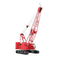
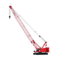
Manitowoc MLC90A-1 Manuals
Manuals and User Guides for Manitowoc MLC90A-1. We have
3
Manitowoc MLC90A-1 manuals available for free PDF download: Operator's Manual, Service And Maintenance Manual, Manual
Manitowoc MLC90A-1 Service And Maintenance Manual (188 pages)
Brand:
Manitowoc
| Category:
Construction Equipment
| Size: 8.78 MB
Table of Contents
See End of this Manual for Alphabetical Index
5
Table of Contents
5
Section 1
13
Continuous Innovation
13
Safety Messages
13
Safety Alert Symbol
13
Signal Words
13
Safe Maintenance Practices
14
Authorized Repair Personnel Only
14
Basic Crane Maintenance Safety
14
Before Starting a Maintenance Procedure
14
Precautions While Working on the Crane
14
Read this Manual
14
Chemical Handling Precautions
15
Fire Hazard Precautions
15
Maintaining Structural Integrity of the Crane
15
Stored Energy Safety Precautions
15
Welding Hazard Avoidance
15
Protection of the Environment
16
Identification and Location of Major Components
16
Returning the Crane to Service
16
Section 2 Hydraulic System
19
Section 2
19
Hydraulic Schematic
21
Hydraulic System Overview
21
Hydraulic Pump Locations
21
Pump 1
22
Pump 2
22
Pump 3
23
Pump 4
23
Pump 5
24
Drum 1 and 2 Motors
25
Drum 3 Motor
25
Motor Identification
25
Drum 4 Motor
26
Travel Motors
27
High Pressure Accessory Valve
28
Low Pressure Accessory Valve
28
Rotating Bed Hydraulic Valves
28
Swing Motors
28
Main Control Valve
29
Hydraulic System Maintenance
32
Disposing of Hydraulic Oil and Parts
32
Safety
32
Storing and Handling Oil
32
Storing and Handling Parts
32
Inspecting the Hydraulic System
33
Inspecting and Replacing Hydraulic Hoses
34
Periodic Inspection
34
Periodic Replacement
34
Replacing Breather
35
Filter
36
Replacing Hydraulic Filters
36
Servicing Suction Strainer
37
Changing Hydraulic Oil
39
Servicing Pumps
39
Replacing Pressure Transducers
41
Replacing a Pressure Transducer
41
Testing a Pressure Transducer
41
Shop Procedures
41
Initial Hydraulic Oil Fill
41
Hydraulic Tests and Calibrations
43
Charge Pressure Test
43
Controls Calibration
43
Drum Speed Test
43
High Pressure Test
43
Pressure Sender Calibration
43
Swing Speed Test
43
Travel Speed Test
43
Disc Brake Operational Test
45
Free Fall Brake Operational Test
45
Accumulator Maintenance
46
Section 3 Electrical System
47
Section 3
47
Electrical Schematic
49
Electrical Power Sequence
49
Battery Power
49
Battery Power Disconnect
49
Crane Electrical Power Distribution
50
Cab Right Console Ground Points
51
Crane Electrical System Ground Points
51
General
51
Rotating Bed and Cab Mount Ground Points
52
Circuit Breakers, Fuses, and Relays
53
Inspect Electrical Components
56
Degradation Due to Severe Environment
56
Every Month or 200 Hours
56
CAN Bus Control System
57
CAN Bus System Overview
57
CAN Bus System Chart
58
Control Module Input/Output (I/O) Types
59
Control Module Naming Conventions
59
Control Modules
59
Crane Control Module (CCM)
60
Safety Control Module (SCM)
60
Input/Output-Large (IOL) Module
61
Input/Output-Small (IOS) Module
61
Control Module Devices
62
Motor Speed Sensors
62
Pressure Transducers
62
Alarms
63
Angle Sensors
63
Fuel Level Sensor
63
Hydraulic Fluid Level Switch
63
Limit Switches-Dual Contact
63
Limit Switches-Single Contact
63
Load Link Sensors
63
Pressure and Vacuum Switches
63
Solenoids
63
Temperature Sensors
63
Control Module Test Voltages
64
Foot Throttle
64
Hand Throttle
64
Proximity Sensors
64
Pump and Motor Voltages and Currents
64
Pump Displacement Controls
64
RCL Beacon
64
Relays
64
Travel and Free-Fall Brake Pedals
64
Wind Speed Indicators
64
Alphabetical Index of Controller Devices
65
Solenoid Valve Identification
66
Test Voltages
67
Section 4 Boom
75
Section 4
75
General Maintenance
77
Rotating Bed Level Sensor
77
Boom Angle Indicator
79
Automatic Boom Stop Limit Switch
81
Automatic Boom Stop Adjustment
81
Automatic Boom Stop Maintenance
81
Physical Boom Stop
83
Physical Boom Stop Adjustment
83
Physical Boom Stop Angles
83
Physical Boom Stop Operation
83
Lattice Section Inspection and Lacing Replacement
83
Boom Electrical Diagram
84
Section 5 Hoists
85
Section 5
85
General
87
Drum Identification
87
All Drums
88
Brake Release
88
Drum Brake
88
Seat Switch
88
Speed Sensor
88
Drums 1 and 2
88
Holding Valve
88
Lowering Load
88
Overview
88
Motor Displacement
89
Pilot-Operated Relief Valve
89
Raising Load
89
Drum 1 Hydraulic Diagram (Without Free Fall)
90
Drum 1 Electrical Diagram
91
Drum 2 Hydraulic Diagram (Without Free Fall)
92
Drum 2 Electrical Diagram
93
Drum 3
95
Holding Valve
95
Lowering Load
95
Motor Displacement
95
Overview
95
Pilot-Operated Relief Valve
95
Raising Load
95
Drum 3 Hydraulic Schematic
96
Drum 3 Electrical Diagram
97
Drum 4
99
Drum 4 Pawl
99
Holding Valve
99
Lowering and Holding a Load
99
Pilot-Operated Relief Valve
99
Raising a Load
99
Drum 4 Hydraulic Diagram
100
Drum 4 Electrical Diagram
101
Drum 1 Hydraulic Diagram
102
Drum 2 Hydraulic Diagram
103
Free Fall System (Optional)
104
Drum Gearbox Oil Change
107
Gear Oil Specifications
107
Initial Operation
107
Monthly
107
Motor Shaft Oil Cavity
107
Oil Analysis
107
Oil Change Procedure
107
Periodic Maintenance
107
Quick-Drain Valve
107
Yearly
107
Drum 4 Pawl
109
Daily
109
Drum 4 Parked
109
Drum 4 Un-Parked
109
Limit Switch Adjustment
109
Maintenance
109
Operation
109
Spring Adjustment
109
Weekly
109
Drum 1 and 2 Minimum Bail Limit
110
Limit Switch Adjustment
110
Pre-Adjustment
110
Speed Sensor-Hoist Motors
111
Replacement
111
Speed Sensor-Free Fall
113
Replacement
113
Anti Two Block (A2B) Switch
114
Locking
114
Unlocking
114
Cranes with Main Hoist Only
115
General
115
Two-Blocking Definition
115
Maintenance
117
Wire Rope Inspection and Replacement
117
Maintain a Wire Rope Condition Report
117
Required Inspection Intervals
117
Wire Rope Care and Replacement Guidelines
117
Wire Rope Lubrication
117
Daily Inspection
118
Determining the Frequency of Inspection
119
Periodic Comprehensive Inspection
119
Broken Rope Wires
120
Reduction in the Rope Diameter
120
Replacement Criteria
120
Distributing Wire Rope Wear
121
Rope that Has Been Idle a Month or more
121
Sheave, Roller, and Drum Inspection
122
Load Block and Hook-And-Weight Ball Inspection
124
Daily Inspection
124
Yearly Inspection
126
Section 6 Swing System
127
General
129
Swing Brake Operation
129
Park Switch Control
129
Holding Brake Switch Control
129
Swing Operation
129
Swing Pump Control
129
Swing Left
131
Cross Port Orifice
131
Swing Right
131
Coasting
131
Swing Alarm
131
Swing Hydraulic Diagram
132
Swing Electrical Diagram
133
Swing System Overview
129
Swing Brake Manual Release
134
Swing Gearbox Oil Change
135
Gear Oil Specifications
135
Oil Analysis
135
Periodic Maintenance
135
Quick-Drain Valve
135
Oil Change Procedure
135
Initial Drain Interval
135
Oil Change Interval
135
Oil Level Interval
135
Section 7 Power Train
137
Section 7
137
Battery Information
139
Battery Gases Are Explosive
139
Battery Safety
139
Causes of Battery Failure
139
Jump-Starting a Battery
139
Lack of Water
139
Overcharging
139
Undercharging
139
Checking Battery State of Charge
140
Loose Hold-Downs
140
Multiple Battery System
140
Overloads
140
Charging
141
Storage
141
Troubleshooting-Slow Cranking
141
Battery Maintenance
142
Battery Disconnect Switch
142
Battery Charger (Optional)
142
Engine Controls
144
Engine Access Panels
144
Engine Component Identification
145
Engine Maintenance
146
Engine Belt Routing
146
Air Cleaner Maintenance
146
Changing the Air Cleaner Filters
146
Daily Inspection
146
Monthly Inspection
146
Engine Radiator
148
Changing Coolant
148
Draining
148
Filling
148
Flushing
148
Adjusting the Engine Throttle
150
Foot Throttle Control
150
Foot Throttle Control Assembly and Calibration
150
Hand Throttle Control
150
Engine Electrical Schematic
152
Exhaust Aftertreatment System
153
DEF Supply Module
153
DEF Tank
153
Engine Regeneration and Inhibit
153
Tier 4 Main Display Icons
153
Aps
154
Coolant Control Valve
154
DEF Dosing Module
154
DOC/DPF Module
154
Drp
154
Excessive Nox Warning System
154
SCR Module
154
Section 8 Undercarriage
157
General
159
Hydraulic Travel System
159
Travel System Overview
159
Travel Brake Operation
159
Directional Control Valves
159
Hydraulic Pump
159
Joystick Control
159
Travel Motors
159
Travel Park Brake Engaged
159
Travel Park Brake Released
159
Travel 2-Speed Operation
160
Travel Cruise Operation
160
Forward Travel Operation
160
Reverse Travel Operation
160
No Travel
161
Travel Motor Flushing
161
Travel Hydraulic Diagram
162
Travel Electrical Diagram
163
Crawler Preventive Maintenance
165
Crawler Tread Slack Adjustment
165
Crawler Tread Slack Measurement
165
Crawler Hand Pump and Cylinder
166
Assembly
167
Maintenance
167
Air Removal
167
Operation
167
Intermediate Roller Bolt Torque
166
Turntable Bearing Alignment
168
Replacing Turntable Bolts
169
Tightening Turntable Bearing Bolt
169
After First 50 Hours of Operation
169
Annually or Every 2,000 Hours of Operation (Whichever Comes First)
169
Crawler Gearbox Oil Change
171
Gear Oil Specifications
171
Oil Analysis
171
Periodic Maintenance
171
Oil Change Procedure
171
Motor Shaft Oil Cavity
171
Initial Operation
171
Weekly
171
Section 9
173
Lubrication
173
Manitowoc 10-I
177
Section 10
177
Counterweight Pins
179
Counterweight Limit Switch
179
Counterweight Pins Overview
179
Disengage (Retract)
179
Engage (Extend)
179
Gantry Cylinder Operation
180
Extend
180
Gantry Cylinders Overview
180
Load Holding
180
Neutral
180
Retract
180
Boom Hoist Operation
180
Crawler Positioning Cylinders Operation
181
Crawler Positioning Cylinders Overview
181
Extend
181
Neutral
181
Retract
181
Hydraulic Cooling Fan Operation
181
Accessory Systems Hydraulic Diagram
182
Accessory Systems Electrical Diagram
183
Advertisement
Manitowoc MLC90A-1 Operator's Manual (218 pages)
Brand:
Manitowoc
| Category:
Construction Equipment
| Size: 45.93 MB
Table of Contents
Table of Contents
5
Section 1
13
Crane Data
13
Crane Weights
13
Outline Dimensions
13
Change of Ownership Registration
13
Manitowoc Dealer
13
Crane Identification
13
Crane Orientation
13
Identification and Location of Components
14
English and Metric Conversions
16
Direct Conversion
16
Inverse Conversion
16
Section 2
19
Continuous Innovation
21
Nameplates and Decals
21
Safety Messages
21
General
21
Safety Alert Symbol
21
Signal Words
21
Symbol Identification
21
Safety and Information Signs
23
Maintaining Signs
23
Ordering Signs
23
Crane Access Points
25
General
25
Getting on or off Crane
25
Personal Fall-Protection
25
Operator Manual/Capacity Chart Storage
26
General
26
Storing Manuals
26
Safe Operating Practices
27
General
27
Read Operator Manual
27
Operator Qualifications
27
Operator Conduct
27
Handling Load
29
Size of Load
29
Attaching Load
29
Lifting/Moving Load
30
Multiple Load Line Operation
31
Signals
32
Holding Load
32
Safety Devices
33
Operational Aids
33
Category 1 Operational Aids
33
Category 2 Operational Aids
34
Assembling, Disassembling, or Operating Crane Near Electric Power and Transmission Lines
35
Electrocution Hazard
35
Set-Up and Operation
35
Electrocution Hazard Devices
36
Electrical Contact
36
Refueling
37
Fire Extinguishers
37
Accidents
37
Safe Maintenance
37
Maintenance Instructions
37
Safe Maintenance Practices
37
Environmental Protection
39
Boom Disassembly Safety
41
General
41
Location
41
Pin Removal
41
Disassembly Precaution
41
Personnel Handling Policy
42
Pedestal/Barge Mounted Cranes
43
Pedestal Mounted Crane
44
Barge Mounted Crane
44
Definition
44
Examples
44
Capacity Charts for Barge Mounted Crane
45
Shock Loading Caused by Barge Dynamics
45
Operation on Barge
45
Barge Mount Definitions
46
Inspection of Barge-Mounted Crane
46
Transporting Crane on Barge
46
Section 3
47
Standard Hand Signals for Controlling Crane Operations
50
Symbols Used on Control Consoles
52
Operating Controls
56
Left Console
60
Right Console
62
Overhead Console
68
Foot Pedals
71
Seat Controls
72
Other Operation Aids
73
Boom Angle Indicator
73
Crane Capacity Beacon (Optional)
73
Crane Level
73
Swing and Travel Alarm
73
Battery Disconnect Switch
74
Crane Cameras
75
Crane Camera Monitor
76
Remote Control
77
Operating Limits Identification
79
Cab Window Operation
81
Opening Windows for Ventilation
81
Exiting Cab in Emergency
81
Operating in Wind
81
Crawler Blocking
82
Preparing Crane for Operation
82
Startup Procedures
83
Operating Procedures
85
Boom Hoist Operation
85
Swing Operation
86
Load Drum Operation-Liftcrane Full Power
88
Load Drum Operation-Liftcrane Free Fall
89
Free Fall Drum Slip and Pedal Response
90
Load Drum Operation-Clamshell
91
Preparing for Clamshell Operation
91
Clamshell Operation in Full-Power
91
Travel Operation
92
Shutdown Procedure or Leaving the Crane Unattended
94
Low Clearance Travel Option
94
Low Clearance Travel Boom Configurations
94
Low Clearance Travel Limitations
94
Fully Rigged Boom
94
Cantilevered Boom Inserts
94
Preparing Fully Rigged Boom for Low Clearance Travel
96
Returning Gantry to Normal Operating Position
96
Preparing Cantilevered Boom Inserts for Low Clearance Travel
98
Returning Gantry to Normal Operating Position
98
Cold Weather Operation
100
Crane Limitations
100
Wire Rope
100
Cold Weather Starting Aid
100
Cooling System
100
Batteries
100
Engine Oil, Gear Oil, and Hydraulic Oil
100
AC Power Supply
102
Generator Installation/Removal
102
Turning AC Power on
102
Turning AC Power off
102
Work Lights
102
Cold Weather Heaters
104
Fuses and Circuit Breakers
106
Boom and Jib Assembly Drawings
111
Liftcrane Boom Butt Capacities
111
Crane Orientation
111
Accessing Parts
111
Assembly and Disassembly Notes
111
Assembly and Disassembly Area
112
Handling Components
112
Retaining Connecting Pins
112
Crane Weights and Shipping Data
112
Parts Storage
112
Parts Box
112
Position Light and Anemometer Option
112
Lifting Sling
113
Shipping Configuration
115
Self-Erect Components
115
Self-Erect Controls
116
Pin and Connecting Hole Cleanliness
117
Electric Cable Cleanliness
117
Connecting/Disconnecting Hydraulic Hoses and Electric Cables
117
Pre-Start Checks
117
Deploy the Crane Platforms as Necessary to Gain Access to Components
117
Engine
117
Gear Boxes
117
Hydraulic System
117
Crane Assembly
119
Prepare Trailer for Unloading
119
Deploy Crawler Steps
119
Deploy Crane Platforms
119
Prepare Cab
121
Raise Handrails
123
Start Engine
125
Configure RCL/RCI for Crane Setup
125
Raise Gantry
125
Travel Crane off Trailer
125
Extend Crawlers
127
Install Hook-And-Weight Ball
129
Unload Trailers
129
Assemble Boom and Jib
133
Install Carbody Counterweight
133
Assemble Crane Counterweight
135
Activate Remote Control
137
Install Crane Counterweight
137
Install Crane Counterweight (Continued)
139
Remove Hook-And-Weight Ball
143
Connect Boom Butt to Boom
143
Connect Boom Pendants to Equalizer
145
Disconnect Equalizer from Boom Butt
145
Configure RCL/RCI for Crane Operation
145
Connect Boom Butt to Boom Top Electric Cables
147
Install Boom Top Position Light and Wind Speed Indicator (Option)
149
Install Boom Top Camera (Option)
149
Install Boom Block-Up Limit Components
149
Install Jib Top Position Light and Wind Speed Indicator (Option)
151
Install Jib Top Camera (Option)
151
Connect Jib Extension Cable
151
Install Jib Block-Up Limit Components
151
Deactivating/Activating a Block-Up Limit Switch
153
Install Load Lines
155
Section 4
111
Boom and Jib Rigging - General
156
Blocked Crawlers
156
Boom Handling
156
Rigging Drawings
156
Identifying Boom and Jib Components
156
Handling Boom and Jib Sections
157
Boom #290 Assembly
159
Assemble Boom Inserts
159
Connect Boom Top to Inserts
159
Install Boom Pendants
160
Install Intermediate Suspension Pendants
161
Install Upper Boom Point
161
Install Optional Rope Guard
163
Install Tagline
163
Complete Boom/Crane Assembly
163
Jib #117 Assembly
165
Prepare Boom
165
Install Jib Bottom
165
Install Jib Inserts
165
Install Jib Top
165
Install Jib/Backstay Pendants
167
Prepare to Raise Jib Strut
167
Deploy Strut Raising Arm
167
Raise Jib Strut
169
Deploy Strut Stops
169
Complete Jib Rigging
169
Raise Boom
170
Pre-Raising Checks
170
Boom Raising Procedure
170
Shipping Crane Components
171
Crane Disassembly
173
Prepare Crane
173
Lower Boom
173
Store Load Lines
173
Remove Boom/Jib Point Electronics
173
Store Strut Stops
175
Deploy Strut Raising Arm
175
Lower Jib Strut
175
Connect Equalizer to Boom Butt
177
Open Boom
179
Disconnect Boom Pendants from Equalizer
181
Disconnect Boom Butt from Boom
181
Install Hook-And-Weight Ball
181
Configure RCL/RCI for Crane Setup
181
Remove Crane Counterweight
183
Remove Crane Counterweight (Continued)
185
Disassemble Crane Counterweight
185
Remove Carbody Counterweight
187
Disassemble Jib and Boom
187
Load Trailers
189
Remove Hook-And-Weight Ball
189
Retract Crawlers
191
Prepare Trailer for Loading
193
Travel Crane Onto Trailer
193
Lower Gantry
193
Secure Operator Cab
194
Lower Handrails
194
Store Crane Platforms
194
Store Crawler Steps
194
Prepare Trailer for Travel
194
Boom #290 Disassembly
194
Jib #117 Disassembly
195
Wire Rope Installation
196
Wire Rope Specifications
196
Wire Rope Storage
196
Seizing and Cutting Wire Rope
196
Anchoring Wire Rope to Drum
196
Winding Wire Rope Onto Drum
198
Anchoring Wire Rope to Wedge Socket
201
Anchoring Wire Rope to Button Socket
203
Pad Eye Usage for Wire Rope Reeving
203
Breaking in Wire Rope
203
Load Line Reeving
205
Guide Sheaves and Drums
205
Dead End Location
205
Load Block Identification
205
Wire Rope Specifications
205
Load Block Reeving
205
Load Block Tieback
206
General
206
Specifications
206
Section 5
207
Lubrication
207
Lube and Coolant Product Guide
209
Section 6
213
Inspection and Maintenance Checklist
213
Fiberglass Maintenance
213
Manitowoc MLC90A-1 Manual (22 pages)
Brand:
Manitowoc
| Category:
Construction Equipment
| Size: 8.53 MB
Table of Contents
Table of Contents
1
Lubrication Symbols
2
General Lubrication
2
Lubrication Intervals
2
Over-Lubrication
3
Lubrication Tips
3
Water in Hydraulic Oil
3
Oil Can Points
3
Wire Rope Lubrication
3
Cylinder Rod Lubrication
4
Environmental Protection
4
Reference Instructions
4
Hydraulic Filter Replacement
4
Lubrication Points
4
Cranelube
4
Approved Lubricants: Normal Factory Fill
5
Approved Lubricants: Arctic Package Option
5
Fluid Capacities
6
Engine Components
7
Upperworks and Lowerworks Lubrication
8
Prior to Use When Crane Is Assembled
9
Daily or Every 8 Hours of Engine Operation or (Whichever Comes First)
9
Weekly or Every 10 Hours of Function Operation or Every 20 Hours of Engine Operation (Whichever Comes First)
11
Weekly or Every 40 Hours of Engine Operation (Whichever Comes First)
11
After First 200 Hours of Engine Operation
13
Monthly or Every 40 Hours of Function Operation or Every 200 Hours of Engine Operation (Whichever Comes First)
13
Monthly or Every 200 Hours of Engine Operation (Whichever Comes First)
13
Quarterly or Every 500 Hours of Engine Operation or (Whichever Comes First)
15
Semi-Annually or Every 200 Hours of Function Operation or Every 1000 Hours of Engine Operation (Whichever Comes First)
15
Semi-Annually or Every 500 Engine Hours of Operation or (Whichever Comes First)
15
Semi-Annually or Every 1000 Engine Hours of Operation or (Whichever Comes First)
15
Yearly or Every 400 Hours of Function Operation or Every 2000 Hours of Engine Operation (Whichever Comes First)
15
Biennially or Every 2000 Hours of Engine Operation (Whichever Comes First)
15
Boom Rigging Lubrication
16
Quarterly or Every 250 Hours of Engine Operation (Whichever Comes First)
17
Yearly or Every 2000 Hours of Crane Operation (Whichever Comes First)
17
Advertisement
Advertisement
Related Products
Manitowoc MLC300
Manitowoc MLC165
Manitowoc MLC165-1
Manitowoc MLC650
Manitowoc MLC100-1
Manitowoc MLC80A-1
Manitowoc MLC100A-1
Manitowoc MLC150-1
Manitowoc Multiplex MS000A06
Manitowoc Servend MDH 402
Manitowoc Categories
Construction Equipment
Ice Maker
Accessories
Commercial Food Equipment
Dispenser
More Manitowoc Manuals
Login
Sign In
OR
Sign in with Facebook
Sign in with Google
Upload manual
Upload from disk
Upload from URL