Sign In
Upload
Manuals
Brands
Lenze Manuals
DC Drives
E82EV223K4B
Lenze E82EV223K4B Manuals
Manuals and User Guides for Lenze E82EV223K4B. We have
1
Lenze E82EV223K4B manual available for free PDF download: System Manual
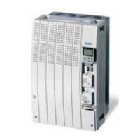
Lenze E82EV223K4B System Manual (588 pages)
0.25 kW...90 kW
Brand:
Lenze
| Category:
DC Drives
| Size: 12 MB
Table of Contents
1 Preface
3
Table of Contents
3
The 8200 Vector Frequency Inverter
5
How to Use this System Manual
7
Information Provided by the System Manual
7
Products to Which the System Manual Applies
8
Legal Regulations
9
Section 2
11
Glossary
13
Terminology and Abbreviations Used
13
Meaning of the Signal Names
14
Total Index
23
Section 3
33
List of Illustrations
33
4 Technical Data
53
General Data/Application Conditions
55
Operation with Rated Power (Normal Operation)
59
Rated Data for Mains Voltage 230 V
59
Rated Data for Mains Voltage 400 V
59
Rated Data for Mains Voltage 500 V
60
Rated Data for Mains Voltage 230 V
61
Mains Voltage 500 V
72
5 Basic Device Installation
83
Important Notes
85
Basic Units in the Power Range 0.25
87
Mounting with Fixing Rails (Standard)
87
Basic Units in the Power Range 3
88
Fig. 5.3-2 Dimensions for Thermally Separated Mounting 0.25
88
Thermally Separated Mounting (Push-Through Technique)
88
Fig. 5.3-3 Thermally Separated Mounting 0.25
89
Fig. 5.3-4 Dimensions for Thermally Separated Mounting 1.5
90
Fig. 5.3-5 Thermally Separated Mounting 1.5
91
Fig. 5.3-6 Dimensions for Mounting in "Cold Plate" Technique 0.25
93
Fig. 5.3-7 DIN Rail Mounting 0.25
94
Fig. 5.3-8 Fixed Lateral Mounting
95
Fig. 5.3-9 Swivelling Lateral Mounting
96
Fig. 5.4-1 Standard Mounting with Fixing Rails 3
97
Mounting with Fixing Rails (Standard)
97
Fig. 5.4-2 Dimensions for Thermally Separated Mounting 3
98
Thermally Separated Mounting (Push-Through Technique)
98
Fig. 5.4-3 Dimensions for Thermally Separated Mounting Cutout 3
99
Fig. 5.4-4 Dimensions for Mounting in "Cold Plate" Technique 3
101
Fig. 5.4-5 Fixed Lateral Mounting
102
Fig. 5.4-6 Swivelling Lateral Mounting
103
Basic Units in the Power Range 15
105
Mounting with Fixing Brackets and Mains Choke (Standard)
105
Fig. 5.5-1 Standard Mounting with Mains Choke 15
105
Fig. 5.5-2 Standard Mounting with Footprint Mains Filter 15
106
Mounting with Fixing Brackets and Footprint Mains Filter
106
Fig. 5.5-3 Standard Mounting with Built-On Mains Filter 15
107
Mounting with Fixing Brackets and Built-On Mains Filter
107
Fig. 5.5-4 Dimensions for Thermally Separated Mounting 15
108
Thermally Separated Mounting (Push-Through Technique)
108
Mounting in "Cold Plate" Technique
109
Fig. 5.5-5 Dimensions for 8200 Vector in "Cold Plate" Technique 15
110
Fig. 5.5-6 Dimensions for 8200 Vector in "Cold Plate" Technique 15
111
Basic Units in the Power Range 45
113
Fig. 5.6-2 Standard Mounting with Footprint Mains Filter 45
114
Fig. 5.6-3 Standard Mounting with Built-On Mains Filter
115
Fig. 5.6-4 Dimensions for Thermally Separated Mounting 45
116
Mounting with Fixing Brackets and Mains Choke (Standard)
117
Basic Units in the Power Range 75
117
Fig. 5.7-2 Standard Mounting with Footprint Mains Filter 75
118
Mounting with Fixing Brackets and Footprint Mains Filter
118
Mounting with Fixing Brackets and Built-On Mains Filter (Mounting Variant 1)
119
Fig. 5.7-4 Standard Mounting with Built-On Mains Filter 75
120
Mounting with Fixing Brackets and Built-On Mains Filter (Mounting Variant 2)
120
Fig. 5.7-5 Dimensions for Thermally Separated Mounting 75
121
Thermally Separated Mounting (Push-Through Technique)
121
6.1 6 Basic Unit Wiring
123
Important Notes
125
Protection of Persons
125
Motor Protection
126
Mains Types/Mains Conditions
126
Operation on Public Mains (Compliance with en 61000-3-2)
127
Operation with E.l.C.bs (Earth-Leakage Circuit-Breakers)
128
Interactions with Compensation Equipment
128
Specification of Cables Used
129
Fig. 6.2-1 Wiring of the Terminal Strips
130
Wiring of Terminal Strips
130
Basics for Wiring According to EMC
131
Requirements on the Cables
131
Fig. 6.3-1 Shielding of the Motor Cable
132
Shielding
132
Fig. 6.3-2 Shielding of Long, Analog Control Cables
133
Installation in the Control Cabinet
133
Fig. 6.3-3 Cable Routing in the Control Cabinet
135
Fig. 6.3-4 Cable Routing in the Cable Duct with Barrier
136
Fig. 6.3-5 Cable Routing in Separated Cable Ducts
136
Wiring Outside the Control Cabinet
136
Basic Units in the Power Range 0.25
139
Basic Units in the Power Range 15
139
Wiring According to EMC (Installation of a CE-Typical Drive System)
140
Basic Units in the Power Range 45
141
Fig. 6.4-2 Mains Connection 230/240 V 0.25
142
Power Connections for 230 V Mains Voltage
142
Fig. 6.4-3 Mains Connection 400/500 V 0.55
143
Power Connections for 400 V Mains Voltage
143
Fig. 6.4-4 Motor Connection 0.25
144
Relay Output Connection
145
Basic Units in the Power Range 3
147
Basic Units in the Power Range 45
147
Wiring According to EMC (Installation of a CE-Typical Drive System)
148
Fig. 6.5-2 Mains Connection 230/240 V 3
150
Power Connections for 230 V Mains Voltage
150
Power Connections for 400 V Mains Voltage
151
Fig. 6.5-4 Motor Connection 3
152
Relay Output Connection
153
Fig. 6.6-1 Wiring According to EMC Requirements 15
156
Fig. 6.6-2 Mains Connection 15
158
Power Connections
158
Fig. 6.6-4 Relay Connections K1 and K2
160
Connection of Relay Outputs K1 and K2
160
Fig. 6.7-1 Wiring According to EMC Requirements 15
164
Fig. 6.7-2 Mains Connection 45
166
Fig. 6.7-3 Motor Connection 45
167
Fig. 6.7-4 Relay Connections K1 and K2
168
Basic Units in the Power Range 75
171
Fig. 6.8-1 Wiring According to EMC Requirements 15
172
Wiring According to EMC (Installation of a CE-Typical Drive System)
172
Fig. 6.8-2 Mains Connection 75
174
Power Connections
174
Fig. 6.8-3 Motor Connection 75
175
Fig. 6.8-4 Relay Connections K1 and K2
176
Connection of Relay Outputs K1 and K2
176
7.1 7 Extensions for Automation
179
Basic Units in the Power Range 0.25
181
Function Modules
181
Fig. 7.2-1 Worksteps
181
Fig. 7.2-2 Additional Worksteps
182
Fig. 7.2-3 Worksteps
182
Fig. 7.2-4 Additional Worksteps
183
Fig. 7.2-5 Front and Rear View
184
Terminal Assignment - Standard I/O E82ZAFSC
184
Terminal Assignment - Standard I/O PT E82ZAFS010
188
Fig. 7.2-7 Front and Rear View
189
Terminal Assignment - Application I/O E82ZAFA
189
Terminal Assignment - Application I/O PT E82ZAFA
189
Fig. 7.2-8 Wiring at Internal /External Supply
192
Bus Function Modules
194
Communication Modules
195
Basic Units in the Power Range 3
197
Function Modules
197
Fig. 7.3-1 Worksteps
197
Fig. 7.3-2 Additional Worksteps
198
Fig. 7.3-3 Worksteps
198
Fig. 7.3-4 Additional Worksteps
199
Fig. 7.3-5 Front and Rear View
200
Terminal Assignment - Standard I/O E82ZAFSC
200
Terminal Assignment - Standard I/O PT E82ZAFS010
204
Fig. 7.3-7 Front and Rear View
205
Terminal Assignment - Application I/O E82ZAFA
205
Fig. 7.3-8 Wiring at Internal /External Supply
208
Terminal Assignment - Application I/O PT E82ZAFA
209
Bus Function Modules
210
Communication Modules
211
Fig. 7.3-10 Relay KSR
213
Connection of Relay Output KSR for "Safe Standstill
213
Basic Units in the Power Range of 15
215
Function Modules
215
Fig. 7.4-1 Worksteps for the Basic Devices 15
216
Wiring of the Terminals "Controller Inhibit (CINH)
216
Fig. 7.4-3 Front and Rear View
218
Fig. 7.4-5 Front and Rear View
223
Fig. 7.4-6 Wiring at Internal /External Supply
226
Fig. 7.4-7 Wiring of the Controller Inhibit with Internal Voltage Supply
228
Fig. 7.4-8 Wiring of the Controller Inhibit with External Voltage Supply
228
Bus Function Modules
229
Fig. 7.4-9 Mounting/Dismounting of the Communication Module
230
Communication Modules
230
Connection of Relay Output KSR for "Safe Standstill
231
Fig. 7.4-10 Relay Connection "Safe Standstill" 15
232
8 Commissioning
233
Before Switching on
235
Fig. 8.3-1 Comparison of V/F Characteristic Control and Vector Control
237
Selection of the Control Mode
237
Parameter Setting with the E82ZBC Keypad
239
V/F Characteristic Control
243
Parameter Setting with the XT EMZ9371BC Keypad
243
Vector Control
244
Important Codes for Quick Commissioning
248
9 Parameter Setting
253
Important Notes
255
Parameter Setting with the E82ZBC Keypad
257
General Data and Application Conditions
257
Fig. 9.3-1 Installation and Commissioning of the E82ZBC Keypad or
258
Installation and Commissioning
258
Fig. 9.3-2 Display Elements and Function Keys of the E82ZBC Keypad
259
Fig. 9.4-1 Installation and Commissioning of XT EMZ9371BC Keypad or
270
Fig. 9.4-2 Display Elements and Function Keys of the XT EMZ9371BC Keypad
270
Installation and Commissioning
270
Display Elements and Function Keys
270
Changing and Saving Parameters
273
Transfer Parameters to Other Controllers
274
Activation of Password Protection
276
Remote Parameter Setting for System Bus Participants
277
Menu Structure
277
Parameter Setting with the XT EMZ9371BC Keypad
277
Menu Structure
278
10.1 10 Function Library
285
Contents
286
Important Notes
287
Fig. 10.3-1 Comparison of V/F Characteristic Control and Vector Control
289
Operating Mode
289
V/F Characteristic Control
289
Vector Control
289
Fig. 10.3-2 Linear and Square-Low V/F Characteristic
291
Sensorless Torque Control with Speed Limitation
292
Fig. 10.3-3 Umin Boost at Linear and Square-Law V/F Characteristic
295
Optimising the Operating Behaviour
303
Slip Compensation
303
Inverter Chopper Frequency
305
Oscillation Damping
306
Behaviour in the Event of Mains Switching, Mains Failure or Controller Inhibit
311
Start Conditions/Flying-Restart Circuit
311
Controller Inhibit
311
Controlled Deceleration after Mains Failure/Mains Disconnection
314
Fig. 10.6-1 Relation between Setpoint and Minimum and Maximum Output Frequency
317
Limit Value Setting
317
Speed Range
317
Current Limits
319
Acceleration, Deceleration, Braking, Stopping
322
Fig. 10.7-1 Acceleration Times and Deceleration Times for Linear Ramp Function Generator
322
Fig. 10.7-2 Acceleration Times and Deceleration Times for Linear Ramp Function Generator
323
Quick Stop
324
Change of Direction of Rotation
325
DC Braking (DCB)
326
AC Motor Braking
328
Configuration of Analog and Digital Setpoints and Actual Values
331
Setpoint Source Selection
331
Fig. 10.8-1 Gain and Offset at Unipolar Setpoint Selection
336
Fig. 10.8-2 Gain and Offset at Bipolar Setpoint Selection
336
Fig. 10.8-3 Gain and Offset at Inverse Setpoint Selection
337
Fig. 10.8-4 Calculation Example for Gain and Offset
337
Digital Setpoints Via Frequency Input
339
Setpoints Via Function "Motor Potentiometer
341
Fig. 10.8-5 Motor Potentiometer with NC Contacts
342
Setpoints Via Keypad
345
Setpoints Via a Bus System
346
Setpoint Changeover (Hand/Remote Changeover)
348
Fig. 10.10-1 Example: Dancer Control with Adding Influence of the Process Controller
353
Fig. 10.10-2 Example: Dancer Control with Subtractive Influence of the Process Controller
354
Fig. 10.12-1 Output Signal of the Function "1/Output Frequency
369
11 Troubleshooting and Fault Elimination
459
Troubleshooting
461
Status Display (Led's on the Controller)
461
Error Analysis with the History Buffer
461
Drive Performance in Case of Errors
463
Error Elimination
465
Maloperation of the Drive
465
Error Messages at the Keypad or in the Parameter Setting Program Global Drive Control
466
Resetting Error Messages
469
12 Network of Several Drives
471
General Information
473
Function
475
Conditions for a Trouble-Free Network of Several Drives
477
Possible Combinations of Lenze Controllers in a Network of Several Drives
477
Mains Connection
478
Fig. 12.4-1 Decentralised Switching of the Mains Supply in Network Operation
479
Fig. 12.4-2 Example: DC Connection of Three Controllers
480
DC-Bus Connection
480
Fuses and Cable Cross-Sections for a Network of Several Drives
482
Protection in DC-Bus Operation
484
Selection
487
Conditions
487
Required Mains Filters or Mains Chokes
488
Supplies - 230 V Controller
489
Supplies - 400 V Controllers
490
Selection Examples
491
Fig. 12.5-1 Example with Two Simultaneously Accelerated and Decelerated Drives
495
Fig. 12.5-2 Example with Two Not Simulateneously Accelerated or Decelerated Drives
495
Central Supply (One Supply Terminal)
497
Central Supply Via External DC Source
497
Fig. 12.6-2 Network of 400 V Controllers with Central Supply
498
Central Supply 400 V with Regenerative Power Supply Unit 934X
498
Decentralised Supply (Several Supply Terminals)
499
Decentralised Supply with Single-Phase or Two-Phase Mains Connection
499
Decentralised Supply with Three-Phase Mains Connection
500
Braking Operation in a Drive System
501
Possibilities
501
Selection
502
13 Braking Operation
503
Braking Operation
505
Braking Operation Without Additional Measures
505
Braking Operation with Three-Phase AC Brake Motor
507
Braking Operation with External Brake Resistor
511
8200 Vector 0.25
512
8200 Vector 15
515
Selection of the Brake Resistors
518
Rating for Lenze Brake Resistors
519
Wiring of Brake Resistor
520
15 Application Examples
525
Pressure Control
527
Fig. 15.2-1 Principle Wiring of a Pressure Regulation
530
Operation with Medium-Frequency Motors
531
Dancer Position Control (Linear Drive)
533
Fig. 15.4-1 Principle Wiring of a Dancer Position Control
534
Fig. 15.5-1 Speed Control with 3-Conductor Sensor
535
Speed Control
535
Fig. 15.6-1 Basic Structure of a Group Drive
541
Group Drive (Operation with Several Motors)
541
Sequential Circuit
543
Fig. 15.8-1 Principle of Setpoint Summation
545
Setpoint Summation (Basic and Additional Load Operation)
545
Power Control (Torque Limitation)
547
Fig. 15.9-1 Power Control Principle Example: Fan
548
16 Signal-Flow Charts
549
Important Notes
551
Fig. 16.3-1 Overview of Signal Flow with Standard I/O
553
Overview of Signal Processing
553
Controller with Standard I/O
553
Fig. 16.3-2 Overview of Signal Flow with Standard I/O and Communication Module
554
Controller with Standard I/O and Communication Module
554
Fig. 16.3-3 Overview of Signal Flow with Application I/O
555
Controller with Application I/O
555
Fig. 16.3-4 Overview of Signal Flow with Application I/O and Communication Module
556
Controller with Application I/O and Communication Module
556
Fig. 16.3-5 Overview of Signal Flow with Communication Module
557
Controller with Communication Module
557
Fig. 16.3-6 Overview of Signal Flow with Fieldbus Function Module on the FIF Interface
558
Controller with Fieldbus Function Module
558
Fig. 16.3-7 Overview of Signal Flow with Fieldbus Function Module (FIF)
559
Controller with Fieldbus Function Module and Communication Module
559
Fig. 16.3-8 Overview of Signal Flow with System Bus Function Module on the FIF Interface
560
Controller with System Bus Function Module
560
Fig. 16.3-9 Overview of Signal Flow with System Bus Function Module (FIF)
561
Controller with System Bus Function Module and Communication Module
561
Fig. 16.4-1 Signal Flow of Speed Setpoint Conditioning
563
Signal Processing in the Function Blocks
563
Speed Setpoint Conditioning (NSET1)
563
Fig. 16.4-2 Signal Flow of Speed Setpoint Conditioning with Application I/O
564
Speed Setpoint Conditioning (NSET1) with Application I/O
564
Fig. 16.4-3 Signal Flow in the Process Controller and Setpoint Processing
565
Process Controller and Setpoint Processing (PCTRL1)
565
Fig. 16.4-4 Signal Flow in the Process Controller and Setpoint Processing with Application I/O
566
Process Controller and Setpoint Processing (PCTRL1) with Application I/O
566
Fig. 16.4-5 Signal Flow in the Motor Control
567
Motor Control (MCTRL1)
567
Fig. 16.4-6 Signal Flow in the Motor Control with Application I/O
568
Motor Control (MCTRL1) with Application I/O
568
Fig. 16.4-7 Signal Flow in Device Control
569
Device Control (DCTRL1)
569
Fig. 16.4-8 Signal Flow in the STAT1 Controller State
570
Fig. 16.4-9 Signal Flow in the STAT1 Device State with FIF Module
570
Controller State (STAT1, STAT2)
570
Fig. 16.4-11 Signal Flow in CAN Objects CAN-IN1 and CAN-IN2
572
Process Data of System Bus Function Module (CAN1, CAN2)
572
Fig. 16.4-12 Signal Flow in CAN Objects CAN-OUT1 and CAN-OUT2
573
Process Data of Fieldbus Function Module (FIF-IN, FIF-OUT)
574
Fig. 16.4-14 Signal Flow of Output Data in the Fieldbus FIF Module
575
Signal-Flow Charts
551
Advertisement
Advertisement
Related Products
Lenze E82EV222K4C
Lenze E82EV152K4C
Lenze E82EV402K4C
Lenze E82EV302K4C
Lenze E82EV752K4C
Lenze 8200 vector E82EV153K4B
Lenze 8200 vector E82EV303K4B
Lenze 8200 vector E82EV453K4B
Lenze 8200 vector E82EV553K4B
Lenze E82EV753K4B
Lenze Categories
DC Drives
Control Unit
Inverter
Engine
Controller
More Lenze Manuals
Login
Sign In
OR
Sign in with Facebook
Sign in with Google
Upload manual
Upload from disk
Upload from URL