Sign In
Upload
Manuals
Brands
Lenze Manuals
DC Drives
8200 vector E82EV303K4B
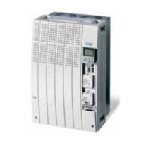
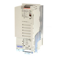
Lenze 8200 vector E82EV303K4B Manuals
Manuals and User Guides for Lenze 8200 vector E82EV303K4B. We have
2
Lenze 8200 vector E82EV303K4B manuals available for free PDF download: System Manual, Mounting Instructions
Lenze 8200 vector E82EV303K4B System Manual (588 pages)
0.25 kW...90 kW
Brand:
Lenze
| Category:
DC Drives
| Size: 12 MB
Table of Contents
1 Preface
3
Table of Contents
3
The 8200 Vector Frequency Inverter
5
How to Use this System Manual
7
Information Provided by the System Manual
7
Products to Which the System Manual Applies
8
Legal Regulations
9
Section 2
11
Glossary
13
Terminology and Abbreviations Used
13
Meaning of the Signal Names
14
Total Index
23
Section 3
33
List of Illustrations
33
4 Technical Data
53
General Data/Application Conditions
55
Operation with Rated Power (Normal Operation)
59
Rated Data for Mains Voltage 230 V
59
Rated Data for Mains Voltage 400 V
59
Rated Data for Mains Voltage 500 V
60
Rated Data for Mains Voltage 230 V
61
Mains Voltage 500 V
72
5 Basic Device Installation
83
Important Notes
85
Basic Units in the Power Range 0.25
87
Mounting with Fixing Rails (Standard)
87
Basic Units in the Power Range 3
88
Fig. 5.3-2 Dimensions for Thermally Separated Mounting 0.25
88
Thermally Separated Mounting (Push-Through Technique)
88
Fig. 5.3-3 Thermally Separated Mounting 0.25
89
Fig. 5.3-4 Dimensions for Thermally Separated Mounting 1.5
90
Fig. 5.3-5 Thermally Separated Mounting 1.5
91
Fig. 5.3-6 Dimensions for Mounting in "Cold Plate" Technique 0.25
93
Fig. 5.3-7 DIN Rail Mounting 0.25
94
Fig. 5.3-8 Fixed Lateral Mounting
95
Fig. 5.3-9 Swivelling Lateral Mounting
96
Fig. 5.4-1 Standard Mounting with Fixing Rails 3
97
Mounting with Fixing Rails (Standard)
97
Fig. 5.4-2 Dimensions for Thermally Separated Mounting 3
98
Thermally Separated Mounting (Push-Through Technique)
98
Fig. 5.4-3 Dimensions for Thermally Separated Mounting Cutout 3
99
Fig. 5.4-4 Dimensions for Mounting in "Cold Plate" Technique 3
101
Fig. 5.4-5 Fixed Lateral Mounting
102
Fig. 5.4-6 Swivelling Lateral Mounting
103
Basic Units in the Power Range 15
105
Mounting with Fixing Brackets and Mains Choke (Standard)
105
Fig. 5.5-1 Standard Mounting with Mains Choke 15
105
Fig. 5.5-2 Standard Mounting with Footprint Mains Filter 15
106
Mounting with Fixing Brackets and Footprint Mains Filter
106
Fig. 5.5-3 Standard Mounting with Built-On Mains Filter 15
107
Mounting with Fixing Brackets and Built-On Mains Filter
107
Fig. 5.5-4 Dimensions for Thermally Separated Mounting 15
108
Thermally Separated Mounting (Push-Through Technique)
108
Mounting in "Cold Plate" Technique
109
Fig. 5.5-5 Dimensions for 8200 Vector in "Cold Plate" Technique 15
110
Fig. 5.5-6 Dimensions for 8200 Vector in "Cold Plate" Technique 15
111
Basic Units in the Power Range 45
113
Fig. 5.6-2 Standard Mounting with Footprint Mains Filter 45
114
Fig. 5.6-3 Standard Mounting with Built-On Mains Filter
115
Fig. 5.6-4 Dimensions for Thermally Separated Mounting 45
116
Mounting with Fixing Brackets and Mains Choke (Standard)
117
Basic Units in the Power Range 75
117
Fig. 5.7-2 Standard Mounting with Footprint Mains Filter 75
118
Mounting with Fixing Brackets and Footprint Mains Filter
118
Mounting with Fixing Brackets and Built-On Mains Filter (Mounting Variant 1)
119
Fig. 5.7-4 Standard Mounting with Built-On Mains Filter 75
120
Mounting with Fixing Brackets and Built-On Mains Filter (Mounting Variant 2)
120
Fig. 5.7-5 Dimensions for Thermally Separated Mounting 75
121
Thermally Separated Mounting (Push-Through Technique)
121
6.1 6 Basic Unit Wiring
123
Important Notes
125
Protection of Persons
125
Motor Protection
126
Mains Types/Mains Conditions
126
Operation on Public Mains (Compliance with en 61000-3-2)
127
Operation with E.l.C.bs (Earth-Leakage Circuit-Breakers)
128
Interactions with Compensation Equipment
128
Specification of Cables Used
129
Fig. 6.2-1 Wiring of the Terminal Strips
130
Wiring of Terminal Strips
130
Basics for Wiring According to EMC
131
Requirements on the Cables
131
Fig. 6.3-1 Shielding of the Motor Cable
132
Shielding
132
Fig. 6.3-2 Shielding of Long, Analog Control Cables
133
Installation in the Control Cabinet
133
Fig. 6.3-3 Cable Routing in the Control Cabinet
135
Fig. 6.3-4 Cable Routing in the Cable Duct with Barrier
136
Fig. 6.3-5 Cable Routing in Separated Cable Ducts
136
Wiring Outside the Control Cabinet
136
Basic Units in the Power Range 0.25
139
Basic Units in the Power Range 15
139
Wiring According to EMC (Installation of a CE-Typical Drive System)
140
Basic Units in the Power Range 45
141
Fig. 6.4-2 Mains Connection 230/240 V 0.25
142
Power Connections for 230 V Mains Voltage
142
Fig. 6.4-3 Mains Connection 400/500 V 0.55
143
Power Connections for 400 V Mains Voltage
143
Fig. 6.4-4 Motor Connection 0.25
144
Relay Output Connection
145
Basic Units in the Power Range 3
147
Basic Units in the Power Range 45
147
Wiring According to EMC (Installation of a CE-Typical Drive System)
148
Fig. 6.5-2 Mains Connection 230/240 V 3
150
Power Connections for 230 V Mains Voltage
150
Power Connections for 400 V Mains Voltage
151
Fig. 6.5-4 Motor Connection 3
152
Relay Output Connection
153
Fig. 6.6-1 Wiring According to EMC Requirements 15
156
Fig. 6.6-2 Mains Connection 15
158
Power Connections
158
Fig. 6.6-4 Relay Connections K1 and K2
160
Connection of Relay Outputs K1 and K2
160
Fig. 6.7-1 Wiring According to EMC Requirements 15
164
Fig. 6.7-2 Mains Connection 45
166
Fig. 6.7-3 Motor Connection 45
167
Fig. 6.7-4 Relay Connections K1 and K2
168
Basic Units in the Power Range 75
171
Fig. 6.8-1 Wiring According to EMC Requirements 15
172
Wiring According to EMC (Installation of a CE-Typical Drive System)
172
Fig. 6.8-2 Mains Connection 75
174
Power Connections
174
Fig. 6.8-3 Motor Connection 75
175
Fig. 6.8-4 Relay Connections K1 and K2
176
Connection of Relay Outputs K1 and K2
176
7.1 7 Extensions for Automation
179
Basic Units in the Power Range 0.25
181
Function Modules
181
Fig. 7.2-1 Worksteps
181
Fig. 7.2-2 Additional Worksteps
182
Fig. 7.2-3 Worksteps
182
Fig. 7.2-4 Additional Worksteps
183
Fig. 7.2-5 Front and Rear View
184
Terminal Assignment - Standard I/O E82ZAFSC
184
Terminal Assignment - Standard I/O PT E82ZAFS010
188
Fig. 7.2-7 Front and Rear View
189
Terminal Assignment - Application I/O E82ZAFA
189
Terminal Assignment - Application I/O PT E82ZAFA
189
Fig. 7.2-8 Wiring at Internal /External Supply
192
Bus Function Modules
194
Communication Modules
195
Basic Units in the Power Range 3
197
Function Modules
197
Fig. 7.3-1 Worksteps
197
Fig. 7.3-2 Additional Worksteps
198
Fig. 7.3-3 Worksteps
198
Fig. 7.3-4 Additional Worksteps
199
Fig. 7.3-5 Front and Rear View
200
Terminal Assignment - Standard I/O E82ZAFSC
200
Terminal Assignment - Standard I/O PT E82ZAFS010
204
Fig. 7.3-7 Front and Rear View
205
Terminal Assignment - Application I/O E82ZAFA
205
Fig. 7.3-8 Wiring at Internal /External Supply
208
Terminal Assignment - Application I/O PT E82ZAFA
209
Bus Function Modules
210
Communication Modules
211
Fig. 7.3-10 Relay KSR
213
Connection of Relay Output KSR for "Safe Standstill
213
Basic Units in the Power Range of 15
215
Function Modules
215
Fig. 7.4-1 Worksteps for the Basic Devices 15
216
Wiring of the Terminals "Controller Inhibit (CINH)
216
Fig. 7.4-3 Front and Rear View
218
Fig. 7.4-5 Front and Rear View
223
Fig. 7.4-6 Wiring at Internal /External Supply
226
Fig. 7.4-7 Wiring of the Controller Inhibit with Internal Voltage Supply
228
Fig. 7.4-8 Wiring of the Controller Inhibit with External Voltage Supply
228
Bus Function Modules
229
Fig. 7.4-9 Mounting/Dismounting of the Communication Module
230
Communication Modules
230
Connection of Relay Output KSR for "Safe Standstill
231
Fig. 7.4-10 Relay Connection "Safe Standstill" 15
232
8 Commissioning
233
Before Switching on
235
Fig. 8.3-1 Comparison of V/F Characteristic Control and Vector Control
237
Selection of the Control Mode
237
Parameter Setting with the E82ZBC Keypad
239
V/F Characteristic Control
243
Parameter Setting with the XT EMZ9371BC Keypad
243
Vector Control
244
Important Codes for Quick Commissioning
248
9 Parameter Setting
253
Important Notes
255
Parameter Setting with the E82ZBC Keypad
257
General Data and Application Conditions
257
Fig. 9.3-1 Installation and Commissioning of the E82ZBC Keypad or
258
Installation and Commissioning
258
Fig. 9.3-2 Display Elements and Function Keys of the E82ZBC Keypad
259
Fig. 9.4-1 Installation and Commissioning of XT EMZ9371BC Keypad or
270
Fig. 9.4-2 Display Elements and Function Keys of the XT EMZ9371BC Keypad
270
Installation and Commissioning
270
Display Elements and Function Keys
270
Changing and Saving Parameters
273
Transfer Parameters to Other Controllers
274
Activation of Password Protection
276
Remote Parameter Setting for System Bus Participants
277
Menu Structure
277
Parameter Setting with the XT EMZ9371BC Keypad
277
Menu Structure
278
10.1 10 Function Library
285
Contents
286
Important Notes
287
Fig. 10.3-1 Comparison of V/F Characteristic Control and Vector Control
289
Operating Mode
289
V/F Characteristic Control
289
Vector Control
289
Fig. 10.3-2 Linear and Square-Low V/F Characteristic
291
Sensorless Torque Control with Speed Limitation
292
Fig. 10.3-3 Umin Boost at Linear and Square-Law V/F Characteristic
295
Optimising the Operating Behaviour
303
Slip Compensation
303
Inverter Chopper Frequency
305
Oscillation Damping
306
Behaviour in the Event of Mains Switching, Mains Failure or Controller Inhibit
311
Start Conditions/Flying-Restart Circuit
311
Controller Inhibit
311
Controlled Deceleration after Mains Failure/Mains Disconnection
314
Fig. 10.6-1 Relation between Setpoint and Minimum and Maximum Output Frequency
317
Limit Value Setting
317
Speed Range
317
Current Limits
319
Acceleration, Deceleration, Braking, Stopping
322
Fig. 10.7-1 Acceleration Times and Deceleration Times for Linear Ramp Function Generator
322
Fig. 10.7-2 Acceleration Times and Deceleration Times for Linear Ramp Function Generator
323
Quick Stop
324
Change of Direction of Rotation
325
DC Braking (DCB)
326
AC Motor Braking
328
Configuration of Analog and Digital Setpoints and Actual Values
331
Setpoint Source Selection
331
Fig. 10.8-1 Gain and Offset at Unipolar Setpoint Selection
336
Fig. 10.8-2 Gain and Offset at Bipolar Setpoint Selection
336
Fig. 10.8-3 Gain and Offset at Inverse Setpoint Selection
337
Fig. 10.8-4 Calculation Example for Gain and Offset
337
Digital Setpoints Via Frequency Input
339
Setpoints Via Function "Motor Potentiometer
341
Fig. 10.8-5 Motor Potentiometer with NC Contacts
342
Setpoints Via Keypad
345
Setpoints Via a Bus System
346
Setpoint Changeover (Hand/Remote Changeover)
348
Fig. 10.10-1 Example: Dancer Control with Adding Influence of the Process Controller
353
Fig. 10.10-2 Example: Dancer Control with Subtractive Influence of the Process Controller
354
Fig. 10.12-1 Output Signal of the Function "1/Output Frequency
369
11 Troubleshooting and Fault Elimination
459
Troubleshooting
461
Status Display (Led's on the Controller)
461
Error Analysis with the History Buffer
461
Drive Performance in Case of Errors
463
Error Elimination
465
Maloperation of the Drive
465
Error Messages at the Keypad or in the Parameter Setting Program Global Drive Control
466
Resetting Error Messages
469
12 Network of Several Drives
471
General Information
473
Function
475
Conditions for a Trouble-Free Network of Several Drives
477
Possible Combinations of Lenze Controllers in a Network of Several Drives
477
Mains Connection
478
Fig. 12.4-1 Decentralised Switching of the Mains Supply in Network Operation
479
Fig. 12.4-2 Example: DC Connection of Three Controllers
480
DC-Bus Connection
480
Fuses and Cable Cross-Sections for a Network of Several Drives
482
Protection in DC-Bus Operation
484
Selection
487
Conditions
487
Required Mains Filters or Mains Chokes
488
Supplies - 230 V Controller
489
Supplies - 400 V Controllers
490
Selection Examples
491
Fig. 12.5-1 Example with Two Simultaneously Accelerated and Decelerated Drives
495
Fig. 12.5-2 Example with Two Not Simulateneously Accelerated or Decelerated Drives
495
Central Supply (One Supply Terminal)
497
Central Supply Via External DC Source
497
Fig. 12.6-2 Network of 400 V Controllers with Central Supply
498
Central Supply 400 V with Regenerative Power Supply Unit 934X
498
Decentralised Supply (Several Supply Terminals)
499
Decentralised Supply with Single-Phase or Two-Phase Mains Connection
499
Decentralised Supply with Three-Phase Mains Connection
500
Braking Operation in a Drive System
501
Possibilities
501
Selection
502
13 Braking Operation
503
Braking Operation
505
Braking Operation Without Additional Measures
505
Braking Operation with Three-Phase AC Brake Motor
507
Braking Operation with External Brake Resistor
511
8200 Vector 0.25
512
8200 Vector 15
515
Selection of the Brake Resistors
518
Rating for Lenze Brake Resistors
519
Wiring of Brake Resistor
520
15 Application Examples
525
Pressure Control
527
Fig. 15.2-1 Principle Wiring of a Pressure Regulation
530
Operation with Medium-Frequency Motors
531
Dancer Position Control (Linear Drive)
533
Fig. 15.4-1 Principle Wiring of a Dancer Position Control
534
Fig. 15.5-1 Speed Control with 3-Conductor Sensor
535
Speed Control
535
Fig. 15.6-1 Basic Structure of a Group Drive
541
Group Drive (Operation with Several Motors)
541
Sequential Circuit
543
Fig. 15.8-1 Principle of Setpoint Summation
545
Setpoint Summation (Basic and Additional Load Operation)
545
Power Control (Torque Limitation)
547
Fig. 15.9-1 Power Control Principle Example: Fan
548
16 Signal-Flow Charts
549
Important Notes
551
Fig. 16.3-1 Overview of Signal Flow with Standard I/O
553
Overview of Signal Processing
553
Controller with Standard I/O
553
Fig. 16.3-2 Overview of Signal Flow with Standard I/O and Communication Module
554
Controller with Standard I/O and Communication Module
554
Fig. 16.3-3 Overview of Signal Flow with Application I/O
555
Controller with Application I/O
555
Fig. 16.3-4 Overview of Signal Flow with Application I/O and Communication Module
556
Controller with Application I/O and Communication Module
556
Fig. 16.3-5 Overview of Signal Flow with Communication Module
557
Controller with Communication Module
557
Fig. 16.3-6 Overview of Signal Flow with Fieldbus Function Module on the FIF Interface
558
Controller with Fieldbus Function Module
558
Fig. 16.3-7 Overview of Signal Flow with Fieldbus Function Module (FIF)
559
Controller with Fieldbus Function Module and Communication Module
559
Fig. 16.3-8 Overview of Signal Flow with System Bus Function Module on the FIF Interface
560
Controller with System Bus Function Module
560
Fig. 16.3-9 Overview of Signal Flow with System Bus Function Module (FIF)
561
Controller with System Bus Function Module and Communication Module
561
Fig. 16.4-1 Signal Flow of Speed Setpoint Conditioning
563
Signal Processing in the Function Blocks
563
Speed Setpoint Conditioning (NSET1)
563
Fig. 16.4-2 Signal Flow of Speed Setpoint Conditioning with Application I/O
564
Speed Setpoint Conditioning (NSET1) with Application I/O
564
Fig. 16.4-3 Signal Flow in the Process Controller and Setpoint Processing
565
Process Controller and Setpoint Processing (PCTRL1)
565
Fig. 16.4-4 Signal Flow in the Process Controller and Setpoint Processing with Application I/O
566
Process Controller and Setpoint Processing (PCTRL1) with Application I/O
566
Fig. 16.4-5 Signal Flow in the Motor Control
567
Motor Control (MCTRL1)
567
Fig. 16.4-6 Signal Flow in the Motor Control with Application I/O
568
Motor Control (MCTRL1) with Application I/O
568
Fig. 16.4-7 Signal Flow in Device Control
569
Device Control (DCTRL1)
569
Fig. 16.4-8 Signal Flow in the STAT1 Controller State
570
Fig. 16.4-9 Signal Flow in the STAT1 Device State with FIF Module
570
Controller State (STAT1, STAT2)
570
Fig. 16.4-11 Signal Flow in CAN Objects CAN-IN1 and CAN-IN2
572
Process Data of System Bus Function Module (CAN1, CAN2)
572
Fig. 16.4-12 Signal Flow in CAN Objects CAN-OUT1 and CAN-OUT2
573
Process Data of Fieldbus Function Module (FIF-IN, FIF-OUT)
574
Fig. 16.4-14 Signal Flow of Output Data in the Fieldbus FIF Module
575
Signal-Flow Charts
551
Advertisement
Lenze 8200 vector E82EV303K4B Mounting Instructions (288 pages)
Brand:
Lenze
| Category:
DC Drives
| Size: 10 MB
Table of Contents
Deutsch
7
Table of Contents
7
1 Über diese Dokumentation
10
Verwendete Konventionen
10
Verwendete Hinweise
11
2 Sicherheitshinweise
12
Bestimmungsgemäße Verwendung
12
Allgemeine Sicherheitshinweise
13
Motor Thermisch Überwachen
16
Restgefahren bei Lenze−Antriebsreglern
18
Sicherheitshinweise für die Installation nach UL
20
3 Technische Daten
21
Allgemeine Daten und Einsatzbedingungen
21
Bemessungsdaten
23
Betrieb mit Bemessungsleistung (Normalbetrieb)
23
4 Mechanische Installation
25
Wichtige Hinweise
25
Grundgeräte IM Leistungsbereich 15
25
Montage mit Befestigungswinkeln (Standard)
25
Montage Thermisch Separiert (Durchstoßtechnik)
28
Montage in "Cold Plate"−Technik
29
Grundgeräte mit der Leistung 45 Kw
31
Montage mit Befestigungswinkeln (Standard)
31
Montage Thermisch Separiert (Durchstoßtechnik)
34
Grundgeräte mit der Leistung 55 Kw
35
Montage mit Befestigungswinkeln (Standard)
35
Montage Thermisch Separiert (Durchstoßtechnik)
37
Umbau der Lüfterbaugruppe bei Durchstoßtechnik
38
Grundgeräte IM Leistungsbereich 75
40
Montage mit Befestigungswinkeln (Standard)
40
Montage Thermisch Separiert (Durchstoßtechnik)
43
5 Elektrische Installation
44
Wichtige Hinweise
44
Verdrahtung
46
Zuordnung Netzdrossel/Filter
46
Klemmleisten Verdrahten
47
Emv−Gerechte Verdrahtung
47
Grundgeräte IM Leistungsbereich 15
49
Netzanschluss
49
Sicherungen und Leitungsquerschnitte nach en 60204−1
50
Sicherungen und Leitungsquerschnitte nach UL
51
Anschluss Motor
52
Grundgeräte IM Leistungsbereich 55 Kw
53
Netzanschluss
53
Sicherungen und Leitungsquerschnitte nach en 60204−1
54
Sicherungen und Leitungsquerschnitte nach UL
55
Anschluss Motor
56
Grundgeräte IM Leistungsbereich 75
57
Netzanschluss
57
Sicherungen und Leitungsquerschnitte nach en 60204−1
58
Sicherungen und Leitungsquerschnitte nach UL
59
Anschluss Motor
60
Anschluss Relaisausgang K1 und K2
61
Anschluss Relaisausgang KSR für Sicherheitsfunktion
63
6 Erweiterungen für die Automatisierung
66
Module
66
Funktionsmodule Montieren und Demontieren
67
Kommunikationsmodule Montieren und Demontieren
71
Reglersperre (CINH) Verdrahten bei Betrieb von Zwei Funktionsmodulen
72
7 Inbetriebnahme
73
Vor dem Ersten Einschalten
73
Parametrierung mit dem Keypad E82ZBC
74
U/F−Kennliniensteuerung
75
Vectorregelung
76
Parametrierung mit dem Keypad XT EMZ9371BC
78
U/F−Kennliniensteuerung
78
Vectorregelung
80
Wichtige Codes für die Schnelle Inbetriebnahme
82
8 Fehlersuche und Störungsbeseitigung
90
Fehlersuche
90
Statusanzeige über Leds am Antriebsregler
90
Störungsanalyse mit dem Historienspeicher
90
Antriebsverhalten bei Störungen
91
Störungsbeseitigung
92
Fehlverhalten des Antriebs
92
Störungsmeldungen
93
Störungsmeldungen Zurücksetzen
96
English
101
1 About this Documentation
104
Conventions Used
104
Notes Used
105
2 Safety Instructions
106
Application as Directed
106
General Safety Information
107
Thermal Motor Monitoring
110
Residual Hazards of Lenze Controllers
112
Safety Instructions for the Installation According to UL
114
3 Technical Data
115
General Data and Operating Conditions
115
Rated Data
117
Operation with Rated Power (Normal Operation)
117
4 Mechanical Installation
119
Important Notes
119
Standard Devices in the Power Range 15
119
Mounting with Fixing Brackets (Standard)
119
Thermally Separated Mounting (Push−Through Technique)
122
Mounting in "Cold Plate" Technique
123
Standard Devices with a Power of 45 Kw
125
Mounting with Fixing Brackets (Standard)
125
Thermally Separated Mounting (Push−Through Technique)
128
Standard Devices with a Power of 55 Kw
129
Mounting with Fixing Brackets (Standard)
129
Thermally Separated Mounting (Push−Through Technique)
131
Modification of the Fan Module for Push−Through Technique
132
Standard Devices in the Power Range 75
134
Mounting with Fixing Brackets (Standard)
134
Thermally Separated Mounting (Push−Through Technique)
137
5 Electrical Installation
138
Important Notes
138
Wiring
140
Mains Choke/Mains Filter Assignment
140
Wiring Terminal Strips
141
Emc−Compliant Wiring
141
Standard Devices in the Power Range 15
143
Mains Connection
143
Fuses and Cable Cross−Sections According to en 60204−1
144
Fuses and Cable Cross−Sections According to UL
145
Motor Connection
146
Standard Devices in the Power Range of 55 Kw
147
Mains Connection
147
Fuses and Cable Cross−Sections According to en 60204−1
148
Fuses and Cable Cross−Sections According to UL
149
Motor Connection
150
Standard Devices in the Power Range 75
151
Mains Connection
151
Fuses and Cable Cross−Sections According to en 60204−1
152
Fuses and Cable Cross−Sections According to UL
153
Motor Connection
154
Connection of Relay Output K1 and K2
155
Connection of Relay Output KSR for Safety Function
157
6 Extensions for Automation
160
Modules
160
Mounting and Dismounting Function Modules
161
Mounting and Dismounting Communication Modules
165
Wiring of Controller Inhibit (CINH) When Two Function Modules Are Operated
166
7 Commissioning
167
Before Switching on
167
Parameter Setting with E82ZBC Keypad
168
V/F Characteristic Control
169
Vector Control
170
Parameter Setting with the XT EMZ9371BC Keypad
172
V/F Characteristic Control
172
Vector Control
174
Important Codes for Quick Commissioning
176
8 Troubleshooting and Fault Elimination
183
Troubleshooting
183
Status Display Via Controller Leds
183
Fault Analysis with the History Buffer
183
Drive Behaviour in the Event of Faults
184
Fault Elimination
185
Drive Errors
185
Fault Messages
186
Resetting Fault Messages
189
Français
193
1 Présentation du Document
196
Conventions Utilisées
196
Consignes Utilisées
197
2 Consignes de Sécurité
198
Utilisation Conforme À la Fonction
198
Consignes Générales de Sécurité
199
Surveillance de la Température du Moteur
202
Dangers Résiduels Pour Les Variateurs de Vitesse Lenze
204
Consignes de Sécurité Pour L'installation Selon UL
206
3 Spécifications Techniques
207
Caractéristiques Générales Et Conditions D'utilisation
207
Caractéristiques Assignées
209
Fonctionnement Avec Puissance Assignée (Fonctionnement Standard)
209
4 Installation Mécanique
211
Remarques Importantes
211
Appareils de Base Pour la Plage de Puissance de 15
211
Montage Avec Équerres de Fixation (Montage Standard)
211
Montage Avec Séparation Thermique (Montage Traversant)
214
Montage Sur Semelle de Refroidissement
215
Appareils de Base D'une Puissance de 45 Kw
217
Montage Avec Équerres de Fixation (Montage Standard)
217
Montage Avec Séparation Thermique (Montage Traversant)
220
Appareils de Base D'une Puissance de 55 Kw
221
Montage Avec Équerres de Fixation (Montage Standard)
221
Montage Avec Séparation Thermique (Montage Traversant)
223
Repositionnement du Module Ventilateur Dans Le Cas D'un Montage Traversant
224
Appareils de Base Pour la Plage de Puissance de 75
226
Montage Avec Équerres de Fixation (Montage Standard)
226
Montage Avec Séparation Thermique (Montage Traversant)
229
5 Installation Électrique
230
Remarques Importantes
230
Câblage
232
Selfs Et Filtres Réseau Adaptés
232
Câblage des Borniers
233
Câblage Conforme CEM
234
Appareils de Base Pour la Plage de Puissance de 15
236
Raccordement Au Réseau
236
Fusibles Et Sections de Câble Selon en 60204−1
237
Fusibles Et Sections de Câble Selon la Norme UL
238
Raccordement du Moteur
239
Appareils de Base Pour Une Puissance de 55 Kw
240
Raccordement Au Réseau
240
Fusibles Et Sections de Câble Selon en 60204−1
241
Fusibles Et Sections de Câble Selon la Norme UL
242
Raccordement du Moteur
243
Appareils de Base Pour la Plage de Puissance de 75
244
Raccordement Au Réseau
244
Fusibles Et Sections de Câble Selon en 60204−1
245
Fusibles Et Sections de Câble Selon la Norme UL
246
Raccordement du Moteur
247
Raccordement des Sorties Relais K1 Et K2
248
Raccordement Sortie Relais KSR Pour Fonction de Sécurité
250
6 Composants D'automatisation Supplémentaires
253
Modules
253
Montage Et Démontage des Modules de Fonction
254
Montage Et Démontage des Modules de Communication
258
Câblage de la Borne de Blocage Variateur (CINH) en Cas D'utilisation de Deux Modules de Fonction
259
7 Mise en Service
260
Avant la Première Mise Sous Tension
260
Paramétrage À L'aide du Clavier de Commande E82ZBC
261
Mode de Fonctionnement en U/F − Courbe Linéaire
262
Régulation Vectorielle
263
Paramétrage À L'aide du Clavier de Commande XT EMZ9371BC
265
Mode de Fonctionnement en U/F − Courbe Linéaire
266
Régulation Vectorielle
267
Codes Importants Pour Une Mise en Service Rapide
269
8 Détection Et Élimination des Anomalies de Fonctionnement
277
Détection des Défauts
277
Affichage D'état Via Les LED Sur Le Variateur de Vitesse
277
Analyse des Anomalies de Fonctionnement À L'aide de L'historique
277
Réaction des Entraînements en Cas D'anomalie de Fonctionnement
278
Elimination des Dysfonctionnements
279
Réaction de L'entraînement en Cas D'erreur/De Dysfonctionnement
279
Messages D'erreur
280
Annulation des Messages D'erreur
284
Advertisement
Related Products
Lenze E82EV302K4C
Lenze E82EV551K4C
Lenze E82EV222K4C
Lenze E82EV751K4C
Lenze E82EV402K4C
Lenze E82EV552K4C
Lenze E82EV113K4C
Lenze 8200 vector E82EV453K4B
Lenze E82EV903K4B
Lenze E82EV
Lenze Categories
DC Drives
Control Unit
Inverter
Engine
Controller
More Lenze Manuals
Login
Sign In
OR
Sign in with Facebook
Sign in with Google
Upload manual
Upload from disk
Upload from URL