Sign In
Upload
Manuals
Brands
Lenze Manuals
DC Drives
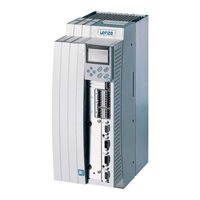
9300 Servo PLC
Lenze 9300 Servo PLC Manuals
Manuals and User Guides for Lenze 9300 Servo PLC. We have
2
Lenze 9300 Servo PLC manuals available for free PDF download: Manual
Lenze 9300 Servo PLC Manual (175 pages)
Global Drive, PLC Developer Studio, IEC 1131 inside
Brand:
Lenze
| Category:
DC Drives
| Size: 3 MB
Table of Contents
Table of Contents
3
1 Preface and General Information
7
About this Manual
7
Conventions in this Manual
7
Pictograms in this Manual
7
Terminology Used
8
What's New
8
Lenze Software Guidelines for Variable Names
9
Hungarian Notation
9
Recommendation for Designating Variable Types
10
Designation of the Signal Type in the Variable Name
11
Special Handling of System Variables
11
2 System Blocks
13
Introduction
13
Definition of the System-Block Inputs/Outputs
15
Automation Interface (Aif1_Io_Automationinterface)
16
Inputs_Aif1 (AIF1_IN)
16
Outputs_Aif1 (AIF1_OUT)
19
Automation Interface (Aif2_Io_Automationinterface)
22
Inputs_Aif2 (AIF2_IN)
22
Outputs_Aif2 (AIF2_OUT)
24
Automation Interface (Aif3_Io_Automationinterface)
27
Inputs_Aif3 (AIF3_IN)
27
Outputs_Aif3 (AIF3_OUT)
29
Inputs_Analog1 (AIN1)
33
Outputs_Analog1 (AOUT1)
34
Inputs_Analog2 (AIN2)
35
Outputs_Analog2 (AOUT2)
36
Drive Control (Dctrl_Drivecontrol)
37
Trip-Set
38
Trip-Reset
40
Dctrl_Wfaultnumber
41
Dctrl_Bexternalfault_B
41
Controller State
41
Output of Digital Status Signals
41
Control Word and Status Word
42
Digital Master Frequency Input (Df_In_Digitalfrequency)
43
Digital Frequency Input X9
44
Technical Data for the Connection of X9 and X10
47
Touch-Probe (TP)
48
Digital Frequency Output (Df_Out_Digitalfrequency)
50
Output Signals on X10
51
Output of an Analog Signal
52
Output of a Speed Signal
52
Encoder Simulation of the Resolver with Zero Track in Resolver Zero Position
52
Direct Output of X8
53
Direct Output of X9
53
Technical Data for the Connection of X9 and X10
54
Digital Inputs/Outputs (DIGITAL_IO)
55
Inputs_Digital (DIGIN)
55
Outputs_Digital (DIGOUT)
56
Free Codes (Fcode_Freecodes)
57
Internal Motor Control (Mctrl_Motorcontrol)
60
Current Controller
62
Additional Torque Setpoint
62
Additional Torque Setpoint
63
Torque Limiting
63
Speed Controller
63
Torque Control with Speed Restriction
64
Speed-Setpoint Restriction
65
Phase-Angle Controller
65
Quickstop QSP
66
Field Weakening
66
Chopping Frequency Changeover
67
Touch-Probe (TP)
68
System Marker Mctrl_Nnmaxc11
69
Monitoring
69
Undervoltage (LU)
69
Overvoltage (OU)
70
Earthfault (Monitoring for Earth Fault OC2)
71
Shortcircuit (Monitoring for a Short-Circuit OC1)
71
Tmot>Setvalue (Motor-Temperature Monitoring OH3 - Fixed)
72
Tmot>C0121 (Motor-Temperature Monitoring OH7 - Adjustable)
72
Ptcovertemp (Motor-Temperature Monitoring OH8)
73
2.13.13.8 Overcurrent Diagram for Fault Signal OC5
73
2.13.13.9 Resolver Monitoring for Wire Breakage Sd2
74
Heatsink Monitoring OH4 (Adjustable)
75
Heatsink Monitoring OH (Fixed)
75
Plant Speed Monitoring Nmax
76
Statebus (STATEBUS_IO)
77
System Markers (SYSTEM_FLAGS)
80
3 Networking
81
System Bus (CAN) in the Lenze Drive System
82
Contact Assignment
82
Wiring of the System Bus
83
System Bus Wiring Complying to EMC
84
Technical Data
85
General Data of the System Bus Network
85
Feasible Bus Length
85
Communication Times
85
Commissioning
86
Programming
86
General
86
Parameter Channels
87
Process Data Channels
88
System Blocks for the System Bus
90
System Bus (CAN1_IO)
90
Inputs_Can1 (CAN1_IN)
90
Outputs_Can1 (CAN1_OUT)
92
System Bus (CAN2_IO)
94
Inputs_Can2 (CAN2_IN)
94
Outputs_Can2 (CAN2_OUT)
96
System Bus (CAN3_IO)
98
Outputs_Can3 (CAN3_OUT)
100
Systembus Management (Can_Management)
102
Synchronization of Control Program Cycles
104
Can_Synchronization
104
Application Example
110
Programming the Application Example
110
Description of the Codes for the System Bus
111
Baud-Rate Setting C0351
111
Defining a Master in a Drive Group C0352
111
Display Code of the Resulting Identifier C0355
114
Boot-Up Setting C0356/1
114
Diagnosis Codes
115
Monitoring
117
Communication Profile of the System Bus
118
Data Description
118
Addressing the Drives
119
The Communication Phases of the CAN Network
120
Parameterization
122
Example: Write a Parameter
125
Example: Read a Parameter
126
Process Data
127
Cyclical Process-Data Objects
127
Cyclical Process-Data Objects
128
Event-Controlled Process-Data Objects, Optionally with Adjustable Cycle Time
131
4 Appendix
136
PLC Functionality
136
System Pous
137
Monitoring
138
Reactions
139
Tripping (L_FWM)
142
Troubleshooting
142
Fault Analysis with the History Buffer
144
Working with the History Buffer
145
Error Messages
146
Reset of Fault Messages
149
Code Table
150
Index
171
Advertisement
Lenze 9300 Servo PLC Manual (112 pages)
Global Drive System bus (CAN)
Brand:
Lenze
| Category:
Recording Equipment
| Size: 1 MB
Table of Contents
Table of Contents
3
Preface and General Information
7
About this Manual
7
Conventions Used in this Manual
7
Layout of the Descriptions
8
Pictographs Used in this Manual
9
Terminology Used
9
Information about the Function Library Version
9
Introduction
11
System Bus Interfaces of the Lenze Plcs
11
Device Identifiers
12
Structure of the CAN Telegram
12
Identifier
12
User Data
14
Network Management (NMT)
15
Sync Telegram for Cyclic Process Data
18
Process Data Telegram
18
Transmitting Parameter Data
19
Telegram Structure
19
Free CAN Objects
25
Recommended Applications for the Individual CAN Objects
26
Configuration (FIF Interface)
27
CAN Baud Rate
27
CAN Boot-Up
27
Node Address (Node ID)
28
Displaying the Set Identifier
50
Cycle Time (FIF-CAN2_OUT/FIF-CAN3_OUT)
51
Delay Time (FIF-CAN2_OUT/FIF-CAN3_OUT)
51
Synchronisation
52
FIF CAN Sync Reaction
52
FIF CAN Sync Identifier
52
FIF CAN Sync Tx Transmission Cycle
52
Reset Node
53
System Bus Management
53
Time Monitoring for FIF-CAN1_IN
54
Bus off
54
Diagnostics
56
FIF CAN Operating State
56
System Blocks
59
Inputs_Can1
64
Outputs_Can1
66
CAN1_IO (Drive PLC)
66
Can2_Io
68
Inputs_Can2
68
Outputs_Can2
70
Can3_Io
72
Inputs_Can3
72
Outputs_Can3
74
Can_Management
76
Can_Synchronization
77
FIF CAN System Blocks (Drive PLC Only)
83
Fif_Can1_Io
83
Fif_Inputs_Can1
83
Fif_Outputs_Can1
85
Fif_Can2_Io
87
Fif_Inputs_Can2
87
Fif_Outputs_Can2
89
Fif_Can3_Io
91
Fif_Inputs_Can3
91
Fif_Outputs_Can3
93
Fif_Can_Management
95
Functions
97
Initialisation (L_Caninit)
97
Driver State (L_Cangetstate)
101
Polling the COB ID Area (L_Cangetreloccobid)
102
Function Blocks
103
Transmit CAN Object (L_Canpdotransmit)
103
Receive CAN Object (L_Canpdoreceive)
107
Index
109
Advertisement
Related Products
Lenze 9300 vector Series
Lenze 9300 vector
Lenze 9350
Lenze L-force 931E
Lenze 9322
Lenze 9324
Lenze 9325
Lenze 9327
Lenze 9328
Lenze 9351
Lenze Categories
DC Drives
Control Unit
Inverter
Engine
Controller
More Lenze Manuals
Login
Sign In
OR
Sign in with Facebook
Sign in with Google
Upload manual
Upload from disk
Upload from URL