Sign In
Upload
Manuals
Brands
Lenze Manuals
DC Drives
9324
Lenze 9324 Servo Controller Drive Manuals
Manuals and User Guides for Lenze 9324 Servo Controller Drive. We have
1
Lenze 9324 Servo Controller Drive manual available for free PDF download: Manual
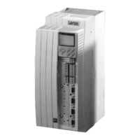
Lenze 9324 Manual (524 pages)
Global Drive cam profiler
Brand:
Lenze
| Category:
DC Drives
| Size: 5 MB
Table of Contents
Table of Contents
7
Technical Data
29
Features
33
General Data/Application Conditions
34
Rated Data
35
Types 9321 to 9325
35
Types 9321 to 9324 with 200 % Overcurrent
36
Types 9326 to 9332
37
Fuses and Cable Cross-Sections
38
Mains Filter
39
Dimensions
39
Important Notes
41
Mechanical Installation
41
Installation
41
Standard Assembly with Fixing Rails or Fixing Brackets
42
Assembly with Thermally Separated Power Stage
43
("Push-Through Technique")
43
Assembly of Variants
46
Electrical Installation
49
Protection of Persons
49
Residual Current Circuit Breakers
49
Mains Disconnection
50
Insulation
50
Replacement of Defective Fuses
50
Protection of the Controller
51
Motor Protection
51
Mains Types/Conditions
52
Interaction with Compensation Equipment
52
Specification of All Cables Used
52
Power Connections
53
Mains Connection
53
Motor Connection
55
Connection of a Brake Unit
57
DC Bus Connection of Several Drives
58
Control Connections
60
Control Cables
60
Control Terminal Assignment
60
Connection Diagrams
62
Motor Temperature Monitoring
68
User-Specific Characteristic for a PTC Resistor
69
Feedback Systems
70
Installation of a CE-Typical Drive System
74
Control
93
Working with Function Blocks/Signal Types
112
Addition Block (ADD)
112
Change of the Terminal Assignments
112
Description of Cam Profile Generation
112
Description of Function Blocks
112
Signal Types
112
Working with Function Blocks
112
Configuration
118
Predefined Configurations
118
Working with Predefined Configurations
118
Configuration with Global Drive Control
119
Control
119
Operating Modes
119
Parameter Setting
119
Signal Types
121
Connection of Function Blocks
123
Freely Assignable Digital Inputs
127
Freely Assignable Analog Inputs
129
Freely Assignable Digital Outputs
129
Freely Assignable Monitor Outputs
130
Entries into the Processing Table
131
Absolute Value Generator (ABS)
140
Automation Interface (AIF-IN)
142
Automation Interface (AIF-OUT)
142
Automation Interface (AIF-OUT)
145
Analog Input Via Terminal 1,2/3,4 (AIN)
147
AND Link (AND)
149
Inverter (ANEG)
153
Analog Output Via Terminal 62/63 (AOUT)
154
Arithmetic Block (ARIT)
156
Arithmetic Block (ARITPH)
158
Changeover Switch for Analog Signals (ASW)
161
Holding Brake (BRK)
164
Close Brake
165
Open Brake
165
Setting Controller Inhibit
166
System Bus (CAN-IN)
168
System Bus (CAN-OUT)
175
Setpoint Conditioning (CCTRL)
179
Main and Auxiliary Position Setpoint
180
Synchronization of Machine and Drive
180
Reset of Main Position Setpoint
181
Speed Precontrol
181
Torque Precontrol
182
Cam Profile Data Conditioning (CDATA)
183
Cam Profile Generation
185
Determination of the Number of Cam Profiles to be Stored
185
Transmission and Storage of Cam Data
185
Determination of the Number of Cam Profiles to be Stored
186
Selection of Cam Profiles Stored for Processing
186
Master Position Processing in CDATA
187
Additional Functions
189
Contouring Error Monitoring (CERR)
192
Determination of the Contouring Error Limits
192
Evaluation of the Contouring Error
192
Output of Status Signals
192
Determination of the Contouring Error Limits
193
Evaluation of the Contouring Error
193
Deactivate Output
194
Output of Status Signals
194
Virtual Clutch (CLUTCH)
195
Disengage Clutch
196
Overload Monitoring
196
Comparator (CMP)
198
Function 1: CMP1-IN1 = CMP1-IN2
199
Function 2: CMP1-IN1 > CMP1-IN2
200
Function 3: CMP1-IN1 < CMP1-IN2
200
Function 4: |CMP1-IN1| = |CMP1-IN2
201
Function 5: |CMP1-IN1| > |CMP1-IN2
201
Function 6: |CMP1-IN1| < |CMP1-IN2
201
Signal Conversion (CONV)
202
Phase Conversion (CONVPHA)
205
Conversion - Stretching Factor (CONVPHD)
206
Encoder Adaptation
206
Interconnection of Function Blocks
206
Phase Conversion (CONVPHPH)
208
Conversion (CONVPHPHD)
209
Speed Conversion (CONVPP)
210
Cam Profile Selection (CSEL)
211
Acceptance of a Converted Value
212
Change of an Input Bit Map
212
Event-Dependent Otuput of a Fixed Value
212
Characteristic Function (CURVE)
213
Characteristic with Four Co-Ordinates
213
Characteristic with Three Co-Ordinates
213
Characteristic with Two Co-Ordinates
213
Characteristic with Three Co-Ordinates
214
Characteristic with Two Co-Ordinates
214
Characteristic with Four Co-Ordinates
215
Characterisitc Function (CURVEC)
216
Dead Band (DB)
219
Controller Control (DCTRLC)
220
Controller Inhibit (CINH)
221
Operation Inhibited (DISABLE)
221
Quick Stop (QSP)
221
Trip Set Trip Reset
221
Controller Status
223
Digital Frequency Input (DFIN)
224
Digital Frequency Output (DFOUT)
227
Output Signals on X10
228
Output of a Speed Signal
229
Output of an Analog Signal
229
Direct Output of X8 (C0540 = 4)
230
Direct Output of X9 (C0540 = 5)
230
Encoder Simulation of the Resolver
230
Digital Frequency Ramp Generator (DFRFG)
231
Quick Stop
232
Detect Phase Difference
233
Ramp Generator Stop
233
Reset
233
Start Via Touch Probe Initiator (Terminal X5/E5)
233
Correction of the Touch Probe Initiator (Terminal X5/E5)
234
Set Offset
234
Digital Frequency Processing (DFSET)
235
Processing of Correction Values
236
Setpoint Conditioning with Stretch and Gearbox Factor
236
Synchronizing on Zero Track or Touch Probe
237
Delay Elements (DIGDEL)
238
Dropout Delay
239
On-Delay
239
General Delay
240
Freely Assignable Digital Inputs (DIGIN)
241
Freely Assignable Digital Outputs (DIGOUT)
242
First Order Derivative-Action Element (DT1)
243
Free Piece Counter (FCNT)
244
Free Codes (FCODE)
245
Free Digital Outputs (FDO)
246
Freely Assignable Input Variables (FEVAN)
248
Fixed Setpoints (FIXSET)
253
Output of a Speed Signal
254
Flipflop (FLIP)
255
Gearbox Compensation (GEARCOMP)
257
Limiter (LIM)
258
Internal Motor Control (MCTRL)
259
Additional Torque Setpoint
261
Chopping Frequency Change-Over
261
Current Controller
261
Field Weakening
261
Phase Controller
261
Quickstop QSP
261
Speed Controller
261
Speed Controller
262
Torque Limiting
262
Limiting of Setpoint Speed
263
Phase Controller
263
Torque Control with Speed Limiting
263
Quickstop QSP
264
7.6.47.10 Chopping Frequency Change-Over
265
Field Weakening
265
Reset of the Mains Failure Control
267
Reset of the Mains Failure Control
273
Restart Protection
273
Application Example
274
Dynamic Adaptation of the Control Parameters
274
Fast Mains Recovery (KU)
274
Motor Potentiometer (MPOT)
275
Master Selection (MSEL)
277
Out of 4 Selection of the Master Value Source
278
Logic NOT (NOT)
279
Conditioning of the Setpoint Speed (NSET)
281
Setpoint Inversion
284
Additional Setpoint
285
Arithmetic Operation
285
S Ramp
285
OR Operation (OR)
286
Oscilloscope Function (OSZ)
289
Process Controller (PCTRL1)
293
Control Characteristic
294
Deactivation of the Process Controller
295
Evaluation of the Output Signal
295
Ramp Generator
295
Value Range of the Output Signal
295
Phase Addition Block (PHADD)
296
Phase Comparator (PHCMP)
297
Actual Phase Integrator (PHDIFF)
299
Signal Adaptation for Phase Signals (PHDIV)
300
Phase Integrator (PHINT)
301
Constant Input Value (PHINT1 and PHINT2)
302
Constant Input Value (PHINT3)
302
Input Value with Change of the Sign (PHINT3)
302
Constant Input Value (PHINT3)
304
Input Value with Change of the Sign (PHINT3)
304
Scaling of Phintx-OUT
305
Compare Actual Position with Values Stored
306
Output of Status Signals
306
Position Memory (PSAVE)
306
Store Position Value
306
Compare Actual Position with Values Stored
307
Output of Status Signals
307
First Order Delay Element (PT1)
308
CW-CCW-QSP Link (R/L/Q)
309
Homing Function (REFC)
309
Control Via Input Signals
311
Homing Modes
311
Output of Status Signals
311
Profile Generator
311
Homing Modes
312
Control Via Input Signals
314
Output of Status Signals
314
Connection of the Function Block
315
Speed/Dig. Frequency Input and Output
315
Loading of the Ramp Generator
316
Ramp Generator (RFG)
316
Calculation and Setting of the Times Tir and Tif
317
Loading of the Ramp Generator
317
Ramp Function Generator for Phase Signals (RFGPH)
318
Sample and Hold Function (S&H)
322
Switching Points (SPC)
323
Switch Points
324
Dead Time
326
Hysteresis
326
Filter Time Constant
327
Filter Time Constant
328
S-Shaped Ramp Generator (SRFG)
329
Output of Digital Status Signals (STAT)
331
Control of a Drive Network (STATE-BUS)
332
Memory Block (STORE)
333
Save STORE1 Phase Signal
334
Save STORE2 Phase Signal
334
STORE1 Control Via TP Input E5
334
Save STORE2 Phase Signal
335
Switch - Digital Frequency (SWPHD)
336
Cycle Times
337
Multi-Axis Synchronization (SYNC)
337
Phase Shift
337
Possible Axis Synchronizations
337
Possible Axis Synchronizations
338
Cycle Times
339
Phase Shift
340
Correction Value Phase Controller
341
Time Window for the Synchronization Via Terminal
341
Configuration Examples
342
Fault Indications
342
Scaling
343
Edge Evaluation (TRANS)
344
Evaluate Positive Edge
345
Evaluate Positive or Negative Edge
345
Evalute Negative Edge
345
Evaluate Positive or Negative Edge
346
Changeover to Alternative Master Value
347
Digital Frequency Input
347
Inching
347
Ramp Function Integrator
347
Virtual Master (VMAS)
347
Changeover to Alternative Master Value
348
Digital Frequency Input
348
Generation of a Virtual Master Value
348
Inching
349
Ramp Function Integrator
349
Positioning Control (VTPOSC)
350
Welding Bar Control (WELD)
352
Basics of Welding Bar Control
353
Cam Data
354
Direction Reversal
358
Stretching, Compression, Offset in y Direction (YSET)
358
Stretching/Compression
358
Direction Reversal
359
Offset
359
Monitoring
360
Reactions
360
Setting of Reactions
361
Monitoring Functions
362
Undervoltage LU
365
Overvoltage OU
366
Heatsink Monitoring OH (Fixed)
368
Heatsink Monitoring OH4 (Adjustable)
368
Heatsink Monitoring OH (Fixed)
369
Heatsink Monitoring OH4 (Adjustable)
369
Motor Temperature Monitoring OH8
370
Motor Temperature Monitoring OH7 (Adjustable)
371
Motor Temperature Monitoring OH3 (Fixed)
372
External Fault Eer
373
Earth Fault Monitoring OC2
374
Monitoring for Short-Circuit OC1
375
Motor Phase Failure Monitoring LP1
376
Resolver Monitoring for Open Circuit Sd2
377
Dig-Set Monitoring Sd3
378
System Fault Ccr
379
Parameter Set Error PR1, PR2, PR3, PR4
380
Parameter Error PRO
381
Communication Error CE0
382
Contouring Error P03
383
Phase Controller Overflow P13
384
Power Stage Identification H07
385
Fault after Automatic Adjustment H30
386
Fault in the Resolver Driver H06
387
System Speed Monitoring Nmax
388
Fault Indication Via Digital Output
389
Parameter Setting
390
Change Parameters
395
Parameter Setting in GDC
395
Keypad
397
Parameter Change Using the Keypad
397
Change Parameters
400
Save Parameter Set
400
Load Parameter Set
401
Parameter Set Transfer
402
Display Functions
404
Password Protection
404
Advertisement
Advertisement
Related Products
Lenze 9321
Lenze 9322
Lenze 9323
Lenze 9325
Lenze 9326
Lenze 9327
Lenze 9328
Lenze 9329
Lenze 9300 vector
Lenze 9352
Lenze Categories
DC Drives
Control Unit
Inverter
Engine
Controller
More Lenze Manuals
Login
Sign In
OR
Sign in with Facebook
Sign in with Google
Upload manual
Upload from disk
Upload from URL