Sign In
Upload
Manuals
Brands
Kollmorgen Seidel Manuals
Amplifier
SERVOSTAR 620
Kollmorgen Seidel SERVOSTAR 620 Manuals
Manuals and User Guides for Kollmorgen Seidel SERVOSTAR 620. We have
2
Kollmorgen Seidel SERVOSTAR 620 manuals available for free PDF download: Assembly & Installation, Assembly, Installation And Commissioning Instructions
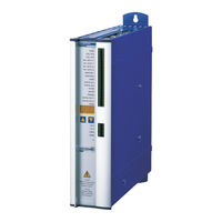
Kollmorgen Seidel SERVOSTAR 620 Assembly & Installation (88 pages)
Digital servo amplifier
Brand:
Kollmorgen Seidel
| Category:
Amplifier
| Size: 3 MB
Table of Contents
Edition
2
Table of Contents
3
Contents
3
Safety Instructions
6
European Directives and Standards
7
UL- Conformance
7
Abbreviations and Symbols
8
Symbols Used in this Manual
8
1 I General
9
About this Manual
9
I.1 about this Manual
9
Prescribed Use (Use as Directed) of the Servo Amplifier
10
Nameplate
11
Instrument Description
11
Package Supplied
11
I.3 Nameplate
11
The Digital Servo Amplifiers of the Series SERVOSTAR 600
12
Operation Directly from Supply
12
Digital Servo Amplifier Concept
13
Connection to Different Mains Supply Networks
14
Components of a Servo System
15
Technical Data
16
External Fusing
16
I.7 Technical Data
16
Permissible Ambient Conditions, Ventilation, Mounting Position
17
Conductor Cross-Sections
17
Recommended Torque
17
LED Display
17
Grounding System
18
Control for Motor-Holding Brake
18
I.8 Grounding System
18
Regen Circuit
19
I.10 Regen Circuit
19
Switch-On and Switch-Off Behavior
20
Stop Function to en 60204 (VDE 0113)
20
Emergency Stop Strategies
21
Installation
23
2 II Installation
23
II.1 Important Instructions
23
II.2 Assembly
24
II.2.1 Dimensions
25
II.3 Wiring
26
II.3.1 Connection Diagram
28
Example of Connections for Multi-Axis System
29
II.3.3 Pin Assignments
30
Notes on Connection Techniques
31
Shielding Connection to the Front Panel
31
Technical Data for Connecting Cables
32
II.4 Setup Software
33
General
33
Software Description
33
Use as Directed
33
Hardware Requirements
34
Operating Systems
34
Installation under WINDOWS 95 / 98 / 2000 / ME / NT
34
II.4.1.3 Hardware Requirements
34
3 III Interfaces
36
III.1
36
Power Supply
36
III.1.1
36
Mains Supply Connection (X0)
36
III.1.2
36
Auxiliary Supply (X4)
36
III.1.3
36
DC-Link (X7)
36
III.1 Power Supply
36
III.2
37
Motor Connection with Brake (X9)
37
III.3
37
External Regen Resistor (X8)
37
III.2 Motor Connection with Brake (X9)
37
III.4
38
Feedback
38
III.4.1
38
III.4 Feedback
38
Resolver Connection (X2)
38
III.4.2
39
Encoder (X1)
39
III.5
40
Control Signals, Monitor Signals
40
III.5.1
40
Analog Setpoint Inputs (X3)
40
III.5 Control Signals, Monitor Signals
40
III.5.2
41
Monitor Outputs (X3)
41
III.5.3
42
Digital Control Inputs (X3)
42
III.5.4
43
Digital Control Outputs (X3)
43
III.6
44
Encoder Simulations
44
III.6.1
44
III.6 Encoder Simulations
44
Incremental Encoder Simulation - a Quad B Position Output (X5)
44
III.6.2
45
SSI Encoder Simulation - Position Output (X5)
45
III.6.3
46
Connection to a SERVOSTAR Master, 5V Signal Level (X5)
46
III.6.3 Interface for Master-Slave Operation, Encoder Input
46
III.6.3.1
46
Interface for Master-Slave Operation, Encoder Input
46
Connection to a Sine-Cosine Encoder (X1)
47
Connection to Encoders with 24V Signal Level (X3)
47
III.6.3.2
47
III.6.3.2 Connection to Encoders with 24V Signal Level (X3)
47
III.6.3.3
47
III.7
48
Interface for Stepper-Motor Controls (Pulse-Direction)
48
III.7.1
49
Connection to Stepper-Motor Controller with 5V Signal Level (X5)
49
III.7.2
49
Connection to Stepper-Motor Controller with 24V Signal Level (X3)
49
III.7.1 Connection to Stepper-Motor Controller with 5V Signal Level (X5)
49
III.8
50
RS232 Interface, PC Connection (X6)
50
III.9
51
Canopen Interface (X6)
51
4 Setup
53
IV.1 Important Notes
53
IV.2 Parameter Setting
55
Multi-Axis Systems
55
Node Address for CAN-Bus
55
Baud Rate for CAN-Bus
55
Key Operation / LED Display
56
Key Operation
56
Status Display
56
Extended Menu Structure
57
Standard Menu Structure
57
IV.3 Error Messages
58
IV.4 Warning Messages
59
Extensions / Accessories Contents
61
Option -AS-, Restart Lock for Personal Safety
61
Advantages of the -AS- Option
61
Functional Description
61
Block Diagram
62
Signal Diagram (Sequence)
62
V.1.3 Block Diagram
62
Installation / Setup
63
Connection Diagram
63
Functional Test
63
Safety Instructions
63
V.1.5 Installation / Setup
63
Application Examples
64
Control Circuit
64
Moving Single Axes or Axis-Groups in Setting-Up Operation
64
Switching off Grouped Axes with Separate Working Areas
64
V.1.6 Application Examples
64
Mains Supply Circuit
65
Expansion Card -I/O-14/08
66
Fitting the Expansion Card
66
Technical Data
66
Light Emitting Diodes (Leds)
66
V.2 Expansion Card -I/O-14/08
66
Position of the Connectors
67
Connector Assignments
68
Select Motion Task Number (Sample)
68
V.2.5 Connector Assignments
68
Connection Diagram
69
Expansion Card -PROFIBUS
70
Position of the Connectors
70
Fitting the Expansion Card
70
Connection Technology
71
Connection Diagram
71
V.3.3 Connection Technology
71
Expansion Card -SERCOS
72
Position of the Connectors
72
Fitting the Expansion Card
72
Light Emitting Diodes (Leds)
73
Connection Technology
73
Connection Diagram
73
Expansion Module -2CAN
74
Position of the Connectors
74
Fitting the Expansion Module
74
Connection Technology
75
Connector Assignments
75
Connection Diagram
75
V.5.3 Connection Technology
75
Accessories
76
External 24V DC / 5A Supply
76
V.6 Accessories
76
External 24V DC / 20A Supply
77
External Regen Resistor Barxxx
78
Motor Choke Box 3YL-20
79
5 V Extensions / Accessories
61
6 Appendix
80
VI.1 Transport, Storage, Maintenance, Disposal
80
VI.2 Removing Faults
81
VI.3 Glossary
83
VI.4 Order Numbers
85
VI.5 Index
86
North America
88
Advertisement
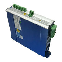
Kollmorgen Seidel SERVOSTAR 620 Assembly, Installation And Commissioning Instructions (68 pages)
Digital servo amplifier
Brand:
Kollmorgen Seidel
| Category:
Amplifier
| Size: 2 MB
Table of Contents
Table of Contents
3
Contents
3
Safety Instructions
6
European Directives and Standards
7
UL- Conformance
7
Abbreviations and Symbols
8
1 I General
9
About this Manual
9
Prescribed Use ("Use as Directed") of the Servo Amplifier
9
Nameplate
10
Instrument Description
10
Package Supplied
10
The Digital Servo Amplifiers of the SERVOSTAR™ 600 Family
11
Operation Directly from Supply
11
Digital Servo Amplifier Concept
12
Block Diagram
13
Components of a Servo System
14
Technical Data of the SERVOSTAR™ 600 Series
15
External Fusing
15
Permissible Ambient Conditions, Ventilation, Mounting Position
16
Conductor Cross-Sections
16
LED Display
16
Grounding System
17
Control for Motor-Holding Brake
17
Regen Circuit
18
Switch-On and Switch-Off Behaviour
19
Stop Function to en 60204 (VDE 0113)
19
Emergency Stop Strategies
20
Installation
21
2 II Installation
22
II.2 Assembly
22
II.2.1 Dimensions of SERVOSTAR™ 600
23
II.3 Wiring
24
Connection Diagram for SERVOSTAR™ 600
26
II.3.2 Example of Connections for Multi-Axis System
27
II.3.3 Pin Assignments for SERVOSTAR™ 600
28
Notes on Connection Techniques
29
Tool List
29
Shielding Connection to the Front Panel
29
Wiring up a Subd-Connector with Shielding
30
II.3.4.4 Assembling the Resolver Connector (Motor End)
31
Wiring up the Motor Power Connector (Amplifier End)
32
Wiring up the Motor Power Connector (Motor End)
33
Technical Data for Connecting Cables
34
II.4 Operator Software
35
General
35
Use as Directed
35
Software Description
35
Hardware Requirements
36
Operating Systems
36
Installation under WINDOWS 95 /98 / NT
36
Interfaces
37
3 III Interfaces
37
Power Supply
37
III.1.1
37
Mains Supply Connection (X0)
37
III.1.2
37
Auxiliary Supply (X4)
37
III.1.3
37
DC-Link (X7)
37
III.2
38
Motor Connection with Brake (X9)
38
III.3
38
External Regen Resistor (X8)
38
III.4
39
Feedback
39
III.4.1
39
Resolver Connection (X2)
39
III.4.2
40
Encoder (X1)
40
III.5
41
Control Signals, Monitor Signals
41
III.5.1
41
Analog Setpoint Inputs (X3)
41
III.5.2
42
Digital Setpoint Inputs (X3)
42
III.5.3
43
Digital Control Outputs (X3)
43
III.5.4
44
Monitor Outputs (X3)
44
III.6
45
Encoder Emulations
45
III.6.1
45
Incremental-Encoder Interface (X5)
45
III.6.2
46
SSI-Interface (X5)
46
III.7
47
RS232 Interface, PC Connection (X6)
47
III.8
48
Canopen Interface (X6)
48
III.9
49
Interface for Stepper-Motor Controls (X5)
49
III.10 Interface for Master-Slave Operation, Encoder Input (X5)
50
4 Commissioning
51
IV.2 Parameter Setting
53
Multi-Axis Systems
53
Key Operation / LED Display
54
Key Operation
54
Structure
55
IV.3 Error Messages
56
IV.4 Warning Messages
56
5 Accessories
57
External 24V DC Supply for One Servo Amplifier
57
External 24V DC Supply for up to 7 Servo Amplifiers
58
External Regen Resistor Barxxx
59
6 Appendix
61
VI.2 Removing Faults
62
VI.3 Glossary
64
VI.4 Index
67
Advertisement
Related Products
Kollmorgen Seidel SERVOSTAR 601
Kollmorgen Seidel SERVOSTAR 603
Kollmorgen Seidel SERVOSTAR 606
Kollmorgen Seidel SERVOSTAR 610
Kollmorgen Seidel SERVOSTAR 610-30
Kollmorgen Seidel 60WKS-M240/3-PB
Kollmorgen Seidel 60WKS-M240/22-PB
Kollmorgen Seidel 60WKS-M240/26-PB
Kollmorgen Seidel SERVOSTAR 600 Series
Kollmorgen Seidel SERVOSTAR 614
Kollmorgen Seidel Categories
Amplifier
Engine
Inverter
Controller
Servo Drives
More Kollmorgen Seidel Manuals
Login
Sign In
OR
Sign in with Facebook
Sign in with Google
Upload manual
Upload from disk
Upload from URL