Sign In
Upload
Manuals
Brands
KLA Tencor Manuals
Laboratory Equipment
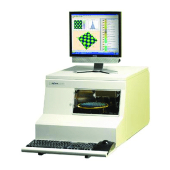
P-16+
KLA Tencor P-16+ Wafer Surface Profiler Manuals
Manuals and User Guides for KLA Tencor P-16+ Wafer Surface Profiler. We have
1
KLA Tencor P-16+ Wafer Surface Profiler manual available for free PDF download: User Manual
KLA Tencor P-16+ User Manual (456 pages)
Profiler P1X / PX
Brand:
KLA Tencor
| Category:
Laboratory Equipment
| Size: 27 MB
Table of Contents
Table of Contents
5
Chapter 1 Introduction & Safety
25
Instrument Overview
25
Safety
25
Introduction
25
Safety Symbols and Related Keywords
25
Lockout/Tagout Procedure
25
Stage and Head Movement Hazards
25
Figure 1.1 Power Cord Plug Lockout/Tagout
27
Chapter 2 Basic Skills
31
Overview
31
Ergonomic Considerations
31
Powering U P the Profiler
32
Introduction
32
Power up Procedure
32
Logging into Profiler Security
32
Figure 2.1 Logon Dialog
32
Starting the Profiler Application
33
Introduction
33
Profiler Start-Up Procedure
33
Figure 2.2 Program Icons
33
Figure 2.3 Profiler Catalog Screen
34
Avigating Etween Rogram Evel Creens
35
N Avigating B Etween P Rogram L Evel S Creens
35
Navigation Procedure
36
Exiting the Profiler Application
36
Introduction
36
Profiler Exit Procedure
36
Figure 2.4 Profiler Configuration Screen
36
Clearing a Status Bar Message
37
Introduction
37
Clearing a Status Bar Message Procedure
37
Rotecting the Tylus Rm Ssembly
38
System Provisions for Stylus Protection
38
Potential Stylus Damage During Scans
38
Table 2.2 Stylus Arm Assembly Protection
38
Figure 2.6 Contact Scan Stylus Tip
39
Loading a Sample
40
Figure 2.7 Scan Recipe Window in the Catalog Screen
40
L Oading a Ample
40
Figure 2.8 XY View Screen
41
Adjusting the Video Image
42
Introduction
42
Video Image Adjustment Procedure
42
Figure 2.9 Video Control Dialog Box
42
Sing Ile Ame Onventions
43
Introduction
43
Naming and Saving Files
43
Saving Video Images
43
Naming and Saving Video Images Procedure
43
Table 2.3 Special Characters Allowed for Naming Purposes
43
Using File Name Convention
43
Exporting Data Graphs
44
Introduction
44
Figure 2.10 Export File Formats in Drop-Down Menu
44
Figure 2.11 Catalog Screen - Database File Manager Icon
44
Figure 2.12 Data Catalog Screen for Export of Data or Recipes
45
Exporting Data from the Database File Manager
46
Table 2.4 Graphics Export Dialog Features
46
Figure 2.14 Data Catalog Screen for Export of Data or Recipes
47
Chapter 3 Scan Recipes
49
Ntroduction
49
Accessing the Scan Recipe Catalog Screen
50
Scan
50
Figure 3.1 Catalog Sequence Recipe Screen
50
Recipe Catalog Screen
51
S Can R Ecipe C Atalog S Creen C Omponents
51
Screen Tools
51
Figure 3.3 Title Bar for Catalog Screen
52
Table 3.1 GEM Status Display
52
Figure 3.4 Menu Bar for Scan Recipe Screen
53
Table 3.2 Edit Menu Options Description
53
Table 3.3 File Menu Options Description
54
Table 3.4 Sample Menu Options Description
54
Table 3.5 Vacuum Menu Options Description
54
Table 3.6 Host Menu Options Description (Only Available with GEM/SECS Option)
55
Table 3.7 Diagnostics Menu Options Description
55
Table 3.8 Loadport Menu Options Description
55
Table 3.9 Task Menu Options Description
55
Figure 3.5 Toolbar Icons
56
Table 3.10 Toolbar for the Scan Recipe Catalog Screen
56
Catalog Screen Access Buttons
57
Table 3.11 Catalog Screen Access Buttons
57
Figure 3.6 Scan Recipe Information in the List Window
58
List Window
58
Figure 3.7 Tool Bar Buttons
59
Table 3.12 Scan Recipe List Window Function Access Buttons
59
System Status Message
60
Creating and Editing a Scan Recipe
60
Figure 3.8 System Status Message Field
60
Accessing the Scan Recipe Editor
61
Recipe Editor for 2D and 3D Scans
61
Figure 3.10 3D Parameters in the Information Display Window
62
Figure 3.9 Recipe Editor for a 2D UNTITLED Recipe
62
Scan Parameter Definition Window
62
Figure 3.11 2D Scan Category Parameters
63
Figure 3.12 X Scan Size (MM)
63
Figure 3.13 Scan Trace Comparison - Large Vs. Small Stylus Radius
65
Figure 3.14 Data Collection When Using a Large Radius Stylus
66
Figure 3.15 Data Collection When Using a Small Radius Stylus
67
Table 3.13 Show Position Options
69
Figure 3.17 Teach Scan Length, from the 2D Scan Teach Button
70
Table 3.14 3D Scan Parameters Summary
70
Figure 3.18 3D Scan Parameters
71
Figure 3.19 Traces - Scan Perimeter with Traces
72
Table 3.15 Show Position Options
73
Figure 3.20 Scan Time - Scan Parameters Definition
74
Figure 3.21 Stylus Parameters (2D and 3D)
75
Table 3.16 Stylus Force Ranges for the Different Head Configurations
76
Table 3.17 Range and Resolution Scan Parameters for the Microhead V LF Head
77
Table 3.18 Range and Resolution Scan Parameters for the Microhead V SR Head
77
Table 3.19 Range and Resolution Scan Parameters for the Microhead V XR Head
77
Figure 3.22 Vertical Ranging - Profile Types
78
Table 3.20 Profile Types
78
Feature Detection (Only for 2D Scans)
79
Figure 3.23 Feature Detection - Recipe Editor
80
Figure 3.24 Feature Detection Point Locations on a Step
81
Table 3.21 Feature Detection Descriptions (See Figure 3.24 and Figure 3.25.)
82
Detection Variables - Feature Detection - Recipe Editor
83
Figure 3.26
83
Figure 3.27
85
Scan Trace (Red) with First Derivative (Dark Blue) Overlaid on the same Graph
85
Figure 3.28 Filters Parameters - Noise Filter Menu
86
Filters and Cursors
86
Figure 3.29 Cursor Parameters - Recipe Editor
87
Analysis Screen with Trace in Need of Leveling
88
Figure 3.30
88
Figure 3.31 Cursor Boundary Setting on Unleveled Trace
89
Figure 3.32
90
Measurement Cursor on Level Trace
90
Setting Measurement Cursors
90
Cursor Parameters - Recipe Editor
91
Figure 3.34
91
Figure 3.35
92
Measurement Cursors - Relative to Feature Detection
92
Figure 3.36 Median Filter Application in Glitch Removal
94
Figure 3.37 2D and 3D Median Filter Options
95
Figure 3.38 y Lead Screw Filter Application
96
Filters Cursors Menu for a 3D Recipe
96
Figure 3.39 3D Measurement Cursor Box
97
Figure 3.40 Recipe Editor - Choosing 3D Cursors
98
Figure 3.41
99
General Parameters
99
Recipe Screen with Unit Output Dialog Box
99
Unit Output
99
Figure 3.42 General Parameters - Recipe Editor
100
Table 3.22 2D General Parameters
101
Roughness and Waviness Parameters
103
Table 3.23 3D General Parameters
103
Figure 3.43 Waviness Vs. Roughness
104
Figure 3.44 Roughness/Waviness Filter Analysis
104
Figure 3.45 Recipe Editor Showing 2D and 3D Roughness/Waviness Parameters
105
Table 3.24 2D Roughness Parameters
106
Table 3.25 2D Waviness Parameters
108
Figure 3.46 3D Roughness Parameters
109
Table 3.26 3D Roughness Parameters
109
Bearing Ratio and Cutting Depth
111
Figure 3.47 Bearing Ration and Cutting Depth Parameters
111
Figure 3.48 2D Bearing Ratio
112
Figure 3.49 Depth for 2D Bearing Ratio
112
Figure 3.50 Cutting Depth
113
Figure 3.51 Bearing Ratio and Cutting Depth Parameters
115
High Spot Count and Peak Count
115
Figure 3.52 High Spot Count
116
Figure 3.53 Peak Count
117
Figure 3.54 2D Peak Count (PC)
117
Histogram Leveling and Depth Analysis
118
Figure 3.55 Histogram Leveling Parameters
120
Figure 3.56
121
Figure 3.57 Multiple Bins (Mode) Used to Define a Plane
121
Histograms of Scans a and B
121
Figure 3.58 Flat Surface Scan of a Single Object
122
Figure 3.59 most Populous Plane Trace Variation
123
Histogram Depth
124
Figure 3.60 Histogram of a Scan
124
Cmp Analysis
125
Introduction
125
Figure 3.61 Histogram Depth
125
Figure 3.62 CMP Analysis - Lines or Array
126
Figure 3.63 CMP Analysis - PADS
127
Arrays
128
Figure 3.64 Sample Array
128
Figure 3.65 er and CR
129
Lines
130
Figure 3.66 Sample Array of Lines
130
Pads
131
Figure 3.67 Sample Pad
131
Figure 3.67
131
Feature Find
132
Figure 3.68 Feature Find Parameter Definition
133
Table 3.27 Feature Find Recipe Parameters
133
Search For: Trench / Line
134
Figure 3.69 Trench / Line Features
135
Figure 3.70 Trench / Line Scan
136
Search for Model Feature
136
Figure 3.71 Edge of an Array of 5 ΜM Lines
137
Figure 3.73 Model Feature Scan
138
Or Bottom to Top
139
Scan Size (ΜM)
139
Search Patterns: Center Outward, Top to Bottom
139
Traces
139
Sampling (Hz)
140
Scan Speed (ΜM/S)
140
Y Spacing (ΜM)
140
Failure Option: Save Search Data, Skip Current Scan, or Scan at Center
141
Scan Offset from Center (ΜM)
141
Feature Characteristics: Feature down or Feature up
142
Feature Depth / Height (Nm)
142
Figure 3.74 5ΜM Lines Measurement Pattern
142
Width (ΜM)
142
Model
143
Figure 3.75 Feature Find Definition for Model Feature
144
Matching Methods: Edge Base or Depth Base
144
Figure 3.76 Dual Damascene Example for Model Feature Using Depth Based Matching
145
Matching Scores
145
Diagnostic Options
146
Reference Point (ΜM)
146
Table 3.28 Diagnostic Options
147
Table 3.29 Standard - Diagnostic Options
147
Table 3.30 Linearity Calibration Only - Diagnostic Options
147
Entering Comments
148
Figure 3.77 Recipe Information Dialog Box
148
Chapter 4 XY View Screen
149
Ntroduction
149
Starting the Xy V Iew
149
Procedure
149
XY View Window Features
149
Figure 4.1 XY View Screen
149
Table 4.1 View Menu Description
151
Table 4.2 die Grid Menu
152
Figure 4.2 Move Extents Dialog Box
153
Figure 4.3 Move to Position Dialog Box
153
Table 4.3 Move Menu
153
Table 4.4 Direction Menu
154
Table 4.5 Actions Menu
155
Table 4.6 Sample Menu
155
Table 4.7 Vacuum Menu
155
Figure 4.4 Distance Dialog Box
156
Table 4.8 Stylus Menu
156
Table 4.9 XY View Window Tool Bar Buttons
156
Setting the Magnification
157
Introduction
157
Changing the Magnification
158
Resetting the Zoom to "0.00
158
Saving the Current Zoom Position
158
Figure 4.5 View Menu and the Stage and Zoom Coordinate Field
158
Focusing the View
159
Introduction
159
Focus the Optics - Top- or Side-View
159
Save Zoom Position Dialog Box
159
Figure 4.6
159
P-16+ Microhead Measurement Head
160
Figure 4.7
160
Positioning the Scan Site
161
Introduction
161
Focusing the Optics (Dual-View Optics)
161
Figure 4.8
161
Figure 4.9 Coordinate System of the KLA-Tencor Profiler Stage
162
Figure 4.10 XY View Screen Tool Bar
163
Table 4.10 Locating a Scan Site
163
Using die Grid Navigation (Optional Feature , P-16+ Only )
164
Introduction
164
Figure 4.11 XY View Screen
164
Figure 4.12 Teach die Grid Screen with Loaded die Grid
165
Creating a die Grid
166
Figure 4.13 Scan Catalog Screen
167
Figure 4.14 Warning - Automatic Null
167
Figure 4.15 Teach die Grid Screen
168
Figure 4.16 Teach die Grid - Teach First Position
169
Figure 4.17 Teach die Grid - Teach Feature
170
Figure 4.18 Teach die Grid - Lower Right Corner
171
Figure 4.19 Teach die Grid - with Feature in Navigation Window
172
Figure 4.20 Teach die Grid - die Grid Simulation in Navigation Window
172
Loading a die Grid (Turning on die Grid Navigation) for a Single Scan
173
Figure 4.21 Sequence Editor with die Grid Menu
174
Figure 4.22 Load Sequence die Grid
175
Clearing a die Grid (Turn off die Grid Navigation)
176
Navigating Across the Wafer Using the die Grid
176
Enabling the Dropout die Option
176
Clearing Dropout dies from the Grid
176
Moving to Partial dies
176
Figure 4.23 die Grid Menu from the Menu Bar
176
Displaying Grid Numbers in the die Grid Navigation Window
177
To Change the Font and Color of the Grid Numbers
177
Aligning the Sample
177
Introduction
177
Procedure
177
Figure 4.24 Setting Alignment Angle
178
Figure 4.25 Move Menu
179
Chapter 5 View Scan Window
181
Screen Unction
181
D S Creen F Unction
181
Figure 5.1 2D Single Scan View Scan Window
181
2D Scan Information Field
182
Figure 5.2 2D Scan Window - Scan Information Field
182
Table 5.1 Scan Screen - Recipe Information Column
182
Table 5.2 View Scan Screen - 2D Location Information Column
182
Figure 5.3 2D Scan Window - Scan Information Field
183
Scan Information Field - 2D Sequence Recipe Column
183
Table 5.3 View Scan Screen - 2D Location Information Column
183
2D View Scan Screen Tool Bar
184
Figure 5.4 Scan Screen - Real Time Trace Window
184
Real Time Scan Trace Window
184
2D View Scan Screen Menu Bar
185
Figure 5.5 2D View Scan Screen Menu Bar
185
Table 5.4 2D View Scan Window Tool Bar Buttons
185
Table 5.5 2D View Scan Screen - File Menu
186
Table 5.6 2D View Scan Screen - View Menu
186
Table 5.10 2D View Scan Screen - Sequence Menu
187
Table 5.7 2D View Scan Screen - Image Menu
187
Table 5.8 2D View Scan Screen - Trace Menu
187
Table 5.9 2D View Scan Screen - Scan Menu
187
Table 5.11 2D View Scan Screen - Pan Menu
188
Screen Unction
189
3D View Scan Screen During a Single Scan
189
D S Creen F Unction
189
Figure 5.6
189
3D Scan Information Field
190
Figure 5.7 3D View Scan Screen During a Scan Sequence
190
Figure 5.8 3D Scan Window - Scan Information Field
190
3D Scan Window - Scan Information Field
191
3D View Scan Screen Tool Bar
191
Figure 5.9
191
Scan Information Field - 3D Sequence Recipe Column
191
3D View Scan Screen Menu Bar
192
Figure 5.10 View Scan Screen Menu Bar
192
Table 5.13 3D View Scan Screen - File Menu
192
Table 5.14 3D View Scan Screen - Trace Menu
192
Table 5.15 3D View Scan Screen - Image Menu
192
Table 5.16 3D View Scan Screen - Scan Menu
193
Table 5.17 3D View Scan Screen - Sequence Menu
193
Table 5.18 3D View Scan Screen - Pan Menu
193
Video Image
193
Figure 5.11 Top View Image of the 3D Scan in Progress
194
Real Time Scan Window
194
Wafer Image Display
194
Scan Site Image Display
195
Abortinga Scan
195
Figure 5.12 Sequence Scan Screen with die Measurement Site Map
195
Introduction
197
Figure 6.1 Sequence Editor Screen
198
S Tarting the S Equence E Ditor a Pplication
198
Figure 6.2
199
Sequence Recipe Catalog Screen
199
Figure 6.3 Scan Sequence Catalog
200
Figure 6.4
201
Sequence Editor for NEW Recipe with Pattern Recognition
201
Figure 6.5 Options Section in the Sequence Editor (Optional Feature, P-16+ Only)
202
Figure 6.6
203
Figure 6.6 die Grid Menu
203
Load die Grid Dialog Box
203
Figure 6.8 Sequence Editor
204
Figure 6.9 Sequence Editor
204
Figure 6.10
205
Pattern Rec. Deskew Teach: Site 1 Screen
205
Deskew Options Dialog Box
206
Figure 6.11 Deskew Options Dialog Box
206
Figure 6.12
207
Figure 6.12 Data Options
207
Figure 6.13
208
Sequence Editor Set up for New Recipe
208
Figure 6.14 Sequence Editor - Teach Scan Location
209
Figure 6.15
210
Teach Location for First Recipe Scan
210
Figure 6.16 Sequence Editor
211
Figure 6.17 Sequence Editor with die Grid Menu
212
Figure 6.18 XY View with Sequence Scan Sites
213
Figure 6.19 Sequence Editor Message Box
213
Figure 6.20 Sequence Editor with New Scan Sites
214
S Equence E Ditor W Indow F Eatures
215
Table 6.1 Sequence Editor Window Buttons
215
Table 6.2 Sequence List Buttons
216
Table 6.3 Options Buttons
216
Table 6.4 Site Buttons
217
Figure 6.21
218
Sequence Editor - Sequence Menu
218
Sequence Information Dialog Box
218
Chapter 6 Sequence Recipe and Data
218
Displaying the Sequence Information Dialog Box
218
Sequence Editor - Mode Menu
219
Figure 6.23
219
E Diting the O Ptions F Ield in the S Equence E Ditor
219
Table 6.5 Mode Drop-Down Menu Options
220
Set Deskew Mode
220
Figure 6.24 Sequence Editor
221
Figure 6.25 Data Options
221
Table 6.8 Export Options
222
Table 6.9 Print Option
222
Table 6.7 Save and Export Options
222
Figure 6.26 Sequence Editor
223
Teaching the Base Angle (P-16+ Only)
223
R Unning a S Equence
224
Figure 6.27 Queue Editor
225
Figure 6.28 Runtime View with the Sequence Queue
226
Adding Sequence Recipes to the Queue at Runtime
226
Correlation Scan Sequence
227
Viewing the Correlation Scan Data
228
Figure 6.30 Correlation Sub-Scan Window
229
Viewing Old Sequence Data
229
Calculating Combined Sequence Statistics
230
Viewing Multi Analysis Results
231
Figure 6.31
232
Sequence Parameter Data Window
232
Sequence Summary Options Dialog Box
232
V Iewing S Equence D Ata
232
Figure 6.32
233
Viewing Sequence Data with the Corresponding Trace, Site-By-Site
233
S Equencing with M Anual D Eskew (a Pplies to B Oth P-16+ and P-6)
234
Deskew Options Dialog Box
235
Deskewing Twice to Align Theta (P-16+ Only)
235
Table 6.10 Pattern Examples
236
Table 6.11 Pattern Search Criteria
237
Figure 6.34
238
Figure 6.34 Profiler Sequence Editor Window
238
Figure 6.35 Pattern Rec. Deskew Teach Window after Teach
239
Pattern Recognition and Deskew Options Dialog Box
240
G Roping with P Attern R Ecognition (P-16+ O Nly )
240
Figure 6.37 Groping Retry Layers
241
Table 6.12 Groping Parameters
241
S Aving S Equences
243
Analysis Screen with File Menu
245
Figure 6.38
245
Figure 6.39 Save Data Set Dialog Box
245
Chapter 7 Analyzing 3D Scan Data
247
Figure 7.1
247
I Ntroduction
247
Scan Catalog Screen with Scan Data Active
247
D a Nalysis S Creen F Eatures
248
Figure 7.2 3D Analysis Screen with 3D Object Displayed
248
Figure 7.3 Analysis Tool Bar Image Rotation Buttons
248
Table 7.1 Automatic Image Rotation Buttons
249
Figure 7.4
250
Figure 7.5
251
Figure 7.7 Analysis Tool Bar Graphics Buttons
252
Right-Click Menu - Mouse Tools
252
Figure 7.9 Analysis Screen - Zoom Active
254
Analysis Screen - Using the Zoom in Icon
255
Figure 7.11
255
Analysis Screen - Unzoom Using Right-Click Menu
256
Analysis Screen - Zoomed in Area
256
Figure 7.12
256
Table 7.2 Manual Image Rotation Buttons
249
Figure 7.4 Manual Image Rotation Handles
250
Image Rotation Using the Rotate Image Menu
251
Figure 7.6 Right-Click Menu – Mouse Tools
252
Figure 7.8 Analysis Screen - Tool Activation
253
Analysis Screen - Zoom Active
254
Analysis Screen with Zoom Box
254
Figure 7.10
254
Table 7.5 Analysis Toolbar Buttons
257
Table 7.6 Analysis Side Toolbar Buttons
258
Figure 7.14
262
Figure 7.14 Analysis Screen Menu Bar
262
Table 7.7 File Menu Operations
262
Table 7.8 Edit Menu Option
263
Table 7.9 View Menu Options
264
Table 7.10 Change Menu Option from the View Menu
268
Table 7.11 Change Menu Option from the View Menu
269
Figure 7.15 Parameters Menu from the Analysis Screen Menu Bar
271
Figure 7.16 3D Recipe Editor
272
3D Recipe Editor with Roughness/Waviness Options
273
Figure 7.17
273
Figure 7.18 Bearing Ratio/Cutting Depth in Recipe Editor
274
Table 7.12 Operations Menu Options (from Menu Bar)
274
Table 7.13 Data Menu Options (from Menu Bar)
276
Table 7.14 Tools Menu Options (from Menu Bar)
277
Activating Line Leveling
278
Figure 7.19
279
Figure 7.20 3D Line by Line Leveling Cursor Parameters
279
Recipe Editor - 3D Cursors Window
279
Figure 7.21 3D Line by Line Leveling Cursor Field
280
Figure 7.22
281
Line Leveling Top View Analysis Screen
281
Customizing the Scan Image
282
Figure 7.23 Recipe Editor with 3D Cursors Window Displayed
282
Setting the Image Proportions
282
Setting the Shading Mode
282
Customizing the View
283
Changing the Image Colors
283
Changing the Scan Height Colors
283
Figure 7.24 Set Viewing Parameters Dialog Box
283
Removing Banding with Line Leveling
283
Figure 7.25 Line Leveling Dialog Box after Cursors Positioned
284
Figure 7.26
285
Image Arithmetic Dialog Box
285
Using Image Arithmetic to Compare Data
285
Saving Scan Data
286
Saving 3D Scan Data
286
Creating and Saving 2D Slice Data from a 3D Scan
287
Figure 7.27 Analysis Screen - Analysis Tool Bar
287
Figure 7.28 3D Analysis Tool Bar with Slice Tool Activated
287
Analysis Screen with View
288
Figure 7.29
288
Analysis Screen with both 2D and 3D Images
289
Analysis Screen with Slice Tool Active
289
Figure 7.30
289
Figure 7.31 Analysis Screen with both 2D and 3D Images
289
Analysis Screen with both 2D and 3D Images
290
Analysis Window with File Menu
290
Figure 7.32
290
Chapter 8 APEX 2D/3D - Getting Started
293
Introduction
293
Licence Agreement
293
Overview of Apex 2D/3D
293
Empty Document
293
Figure 8.1
293
Figure 8.2 General Toolbar
294
Figure 8.3 Studiables Directory
294
Chapter 9 Stress (Optional Feature)
297
Introduction
297
Theory
297
Stoney Equation
297
Figure 9.1 Stress Calculation Regions
298
Polynomial Fit
299
Least Square Fit
300
Figure 9.2 13 Point Least Square Fit Calculation Illustration
300
The 2D Stress Application Window (P-16+ and P-6)
301
The Stress Screen Tool Bar
301
Table 9.1 Tool Bar Icons
301
Stress Recipe Catalog
302
Stress Scan Data File Catalog
302
Creating a Stress Recipe
302
Number of Stress Points
302
Scan Start Position
302
Scan Parameters
303
Substrate Specification
303
Creating Stress Data
304
Load a Wafer on the Stress Locator
304
Loading Wafers
304
Table 9.2 Elastic Constant of Substrates
304
Precision Locator on the Stage (P-16+)
305
Taking a Pre-Stress Scan
306
Taking a Post-Stress Scan
306
Analyzing Stress Scan Results
306
Table 9.3 Stress Calculation Results Box Contents
307
Chapter 10 3D Stress (Optional Feature, P-16+ Only)
309
Introduction
309
Definitions
309
Table 10.1 Common Terms Defined
309
The 3D Stress Application Window
311
Figure 10.1 the 3D Stress Catalog Window
311
Figure 10.2 3D Stress Buttons Found in the 3D Stress Catalog Window
311
Figure 10.3 3D Stress Recipe Editor Window
312
Creating a 3D Stress Recipe
312
Table 10.2 Field Descriptions in the 3D Stress Recipe Editor Window
313
Table 10.3 Field Descriptions in the Alignment Section of the Recipe Editor
313
Adding New Substrates to the Substrate Database
314
Figure 10.4
314
Figure 10.4 Edit Substrates Window
314
Table 10.4 Field Descriptions in the Substrate Specification Section of the Recipe Editor
314
Figure 10.5 Substrate Properties Window
315
Figure 10.6 Edit Substrate Buttons
315
Saving a Stress Recipe
315
Figure 10.7 Recipe Dropdown Menu
316
Taking 3D Stress Data
316
Figure 10.8 3D Stress Catalog Window and Stress Data Button
317
Figure 10.9 Pre and Post Measurement Data Designation
317
Figure 10.10 Film Thickness Window
318
Figure 10.11 Default Format of the 3D Stress Analysis Window in Apex
319
Figure 10.12 Stress Map Calculated by Apex Software
320
Figure 10.13 3D Stress Toolbar in Apex Software
320
Table 10.5 Tool Bar Icons for the Stress Map Image Cursors
321
Table 10.6 Tool Bar Icons for Adjusting Image Rendered
322
Figure 10.14 3D Stress Dialogue Box
323
Figure 10.15 Angular Data Image in Apex Software
324
Figure 10.16 Save as Window for Saving Only the Xml Data Files
325
Figure 10.17 3D Stress File Selection Dialogue Box
326
Saving the Stress Difference Data
326
Figure 11.1 Log on Dialog
327
I Ntroduction
327
Figure 11.2 Log on Dialog at Runtime
328
Figure 11.3 Security Configuration Editor
329
P Rocedure to M Odify S Ecurity S Ettings
330
Figure 11.4 XML Configuration Saved
331
Group User Admin - Manage Users
331
L Ogin and L Ogout P Rocedure
328
C Onfiguring Kla-T Encor S Ecurity
329
Table 11.1 Security Configuration Editor Sections
330
Figure 11.6 Load from os Import Users
332
Figure 11.7 Choose Users from Local System
332
P Rocedure to Change the a Uto L Ogon U Ser P Assword
332
Figure 11.8 Edit Users
333
Figure 11.9 Change User Password
333
A Ccess P Olicy S Ettings
334
Figure 11.10 Save Users to Local System
334
Figure 11.11 Access Policy Settings
335
P Rocedure to C Hange a Ccess P Olicy S Ettings
335
Figure 11.12 Edit Access Policy Setting for Windows Shutdown Command
336
Figure 11.13 Saving the Access Policy Setting
336
Table 11.2 Access Policy Settings
337
Figure 11.14 Application Lifecycle
341
Figure 11.15 Add Programs to the Control List
342
P Rocedure to C Hange a Pplication L Ifecycle S Ettings
342
Figure 11.16
343
Figure 11.16 Save Changes to the Control List
343
G Lobal S Ettings
343
Figure 11.17 Global Settings
344
Figure 11.20 My Computer/Manage
347
Figure 11.21 User Account Management
348
Figure 11.22 New User Interface
348
Procedure to Create a New User Account
348
Figure 11.23 Security Group Management
349
Figure 11.24 Profiler Security Group Members
350
Figure 11.25 Add a User to a Security Group
351
Figure 11.26 Windows XP User:engineer
352
Figure 11.27
352
Figure 11.27 Add a Security Group to a User
352
Figure 11.28 Examples of Operator and Engineer Security Group Access
353
Figure 11.18 Modify Global Settings
345
Figure 11.19 Persist Autologon to Operating System
345
P Rocedure to C Hange the G Lobal S Ettings
345
S Ecurity G Roups
346
C Omputer M Anagement /U Ser a Ccounts
347
Chapter 12 Calibrations
355
Standard Calibration Matrix
355
A Pplied F Orce C Alibration
356
Figure 12.2 Calibrations Screen
356
V Ideo C Alibration
357
Figure 12.4 Manual Load from the Video Calibration Screen
358
Figure 12.5 Message Prompt and Focus Button
359
Figure 12.6 XY Video Display Message Box
360
S Can P Osition O Ffset C Alibration
360
Calibration Procedure:
361
Chapter 11 System Security
361
Figure 12.8 Navigation Window Right-Click Menu
362
Figure 12.10 Calibration Menu in the Calibration Screen
363
Figure 12.11 Step Height Calibration Options Dialog Box
364
Figure 12.12 Saving the New Calibration
366
P-16 S Eries L Evel C Alibrations
366
Figure 12.13 Calibration Screen
367
Level Calibration Procedure
367
Figure 12.14 Level Calibration Warning
368
Figure 12.15 Tilt Calibration System Status Load Wafer Message
368
Figure 12.16 Tilt Axis Angle Calibration Value Dialog Box
369
Level Calibration Confirmation
369
Figure 12.17 Activating Focus in the XY VIEW Screen
370
Figure 12.18 Move to Menu
370
Figure 12.19 Move to Position Dialog Box
371
Figure 12.20 Teach Lowest Elevator Position Screen
371
Figure 12.21 Move to Menu
372
Figure 12.22 Move to Position Dialog Box
372
Figure 12.23 P6 Precision Standard Locator Chuck
373
P-6 L Eveling
373
I Ntroduction
375
Table 13.1 Available L-Stylus Radius
375
S Tylus R Emoval and R Eplacement
376
Chapter 13 Stylus Change Procedure
377
Figure 13.1 Profiler [Catalog] - Click on the Calibration Icon
377
Figure 13.2 Stylus Force Calibration Button
377
Stylus Removal
377
Figure 13.3 Configuration Screen
378
Figure 13.4 Stylus ID Dialog Box
379
Figure 13.5 Message Box for Stylus Name Affirmation
379
Figure 13.6 Message Box for Stylus Change Permission
380
Figure 13.7 Supporting Stylus Mount During Stylus Change
380
Stylus Replacement
381
Figure 13.10 Supporting Stylus and Mount During Tightening Procedure
382
Figure 13.11 Sensor Assembly - Seating the New Stylus
382
Figure 13.12 Message Box for Stylus Change Permission
383
Scan Position Offset Calibration
383
Figure 13.13 KLA-Tencor Procal Wafer
384
Figure 13.14 Message Box Requesting SPO Standard Placement
384
Figure 13.15 Manual Load from the Scan Offset Calibration Window
385
Figure 13.16 Scan Position Offset Calibration Options Dialog Box
385
Figure 13.17 Window Buttons - _OFF150- Recipe Editor
386
Figure 13.18 Scan Position Offset Calibration Options Dialog Box
387
Figure 13.19 Set Default Dialog Box
387
Figure 13.20 Scan Parameter Definition - _OFF150 - Recipe Editor
388
Figure 13.21 ZOOM in - Scan Offset Calibration
388
Figure 13.22 KLA-Tencor Procal Wafer
390
Figure 13.23 Aligning the Tool with Screen Crosshair
390
Figure 13.25 Manual Load from the Scan Offset Calibration Window
391
Figure 13.26 Scan: _OFF150 Window
392
Figure 13.27 Trace Path through Upper Triangle
392
Figure 13.28 Data Analysis Window
393
Figure 13.29 Scan Data Portion of the Analysis Window
393
Figure 13.30 Coarse Scan Data Analysis Window
394
Figure 13.31 "Unknown Situation" Corrective Action
394
Figure 13.32 Pre Acceptance Analysis Screen
395
Figure 13.33 Analysis Screen with Cursors Manually Placed
395
Figure 13.34 Scan Offset Calibration, Analysis Information Window
396
Figure 13.35 Hand Selecting the Triangle Data in Analysis Screen
397
Figure 13.36 Accepting Adjusted Scan Results
397
Figure 14.1 System Geometry
399
O Perating E Nvironment
399
Level and Tilt
400
Figure 14.2 Example Sample Stage Tilt Calibration Scan
401
Figure 14.3 Example Sample Stage X-Direction Cross-Section Calculation
402
Chapter 14 Configuration
403
Figure 14.5 Stylus Details
403
I Ntroduction to S Ystem C Onfiguration
403
Figure 14.6 Choose Calibration
404
S Tage C Onfiguration
404
Figure 14.7 Stage Configuration Parameters
405
Theta Soft Home Position
405
Figure 14.8 Configuration Screen - Lowest Elevator Position
406
Elevator Focus Speed
407
Elevator Safe Position
408
Figure 14.9 Configuration Screen
408
Figure 14.10 System Configuration Dialog Box
409
Figure 14.11 Instrument Setup Dialog Box
409
Figure 14.12 Configuration Screen
410
S Afe a Rea C Onfiguration
410
Figure 14.13 Safe Area Configuration - Sample Configuration Menu
411
Figure 14.14 Safe Area Configuration - Edit Safe Area Values
412
Figure 14.15 License Options
413
Figure 14.16 Recipe Transport Options
414
Figure 14.17 Sequence Execution Options Dialog Box
415
S Equence E Xecution O Ptions
415
Figure 14.18 Proximity Sensor Configuration
416
Options
416
P Recision L Ocators (P-16+ O Nly )
417
Figure 14.19 Lightweight Stage Table Top
418
Figure 14.20 Precision Locator
418
Figure 14.21 Three Point Disk Locator
419
Figure 14.22 Three Point Disk Locator Base Plate
420
Figure 14.23 Center Hub Screw
420
Figure 14.24 Disk Support for the Three Point Disk Locator
421
Precision Locators - Description
422
Figure 14.25 P-6 Precision Standard Locator Chuck
423
P-6 P Recision L Ocators
423
Figure 14.26 P-6 Stress Chuck
424
Chapter 15 Preventive Maintenance
425
I Ntroduction
425
Weekly PM Procedures
425
Monthly PM Procedures
426
Semi-Annual PM Procedures
426
Chapter 16 Backup and Restore
427
Figure 16.1 Windows Run Function
427
Figure 16.2 Profiler Backup Command
428
Figure 16.3 Profiler Backup Command Confirmation
429
Figure 16.4 Profiler Backup Complete
429
Figure 16.5 Profiler Backupfiles
430
Figure 16.6 Profiler Restore Command
431
Figure 16.8 Profiler Restore Directory Selection
432
Figure 16.9 Profiler Restore Command Confirmation
432
Figure 16.10 Profiler Restore Complete
433
Figure A.1 Hazardous Content Symbol
436
Table A.1 Hazardous Materials List
436
Appendix A Hazardous Materials
435
Appendix A P Series Profiler - Preparing for Shipment
439
Table B.1 Minimum Parts Required
439
Figure 1.1 P-6 Hook
441
Advertisement
Advertisement
Related Products
KLA Tencor P-6
KLA Tencor Categories
Laboratory Equipment
More KLA Tencor Manuals
Login
Sign In
OR
Sign in with Facebook
Sign in with Google
Upload manual
Upload from disk
Upload from URL