Sign In
Upload
Manuals
Brands
Keysight Technologies Manuals
Test Equipment
InfiniiVision MSO-X 6004A
Keysight Technologies InfiniiVision MSO-X 6004A Manuals
Manuals and User Guides for Keysight Technologies InfiniiVision MSO-X 6004A. We have
1
Keysight Technologies InfiniiVision MSO-X 6004A manual available for free PDF download: Service Manual
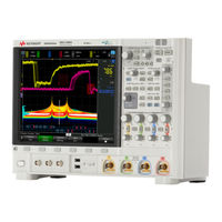
Keysight Technologies InfiniiVision MSO-X 6004A Service Manual (130 pages)
Brand:
Keysight Technologies
| Category:
Test Equipment
| Size: 23.08 MB
Table of Contents
Figure 51. Exploded View 2 of
2
In this Service Guide
3
Table of Contents
5
Figures
9
Tables
11
1 Characteristics and Specifications
13
Power Requirements
13
Measurement Category
14
Measurement Category Definitions
14
Maximum Input Voltages
15
Environmental Conditions
16
Specifications
16
Contact Us
16
2 Testing Performance
17
Overview
18
List of Test Equipment
19
Table 1. List of Test Equipment
19
Conventions
20
Table 2 Conventions
20
Table 3. Materials Required to Construct the Test Connectors
21
To Construct the Test Connector (for Use with MSO Models Only)
21
Figure 1 Constructing the 8-By-2 Connector
22
To Test Digital Channels (MSO Models Only)
23
To Verify Digital Channel Threshold Accuracy (MSO Models Only)
24
When to Test
24
What to Test
24
Verifying Test Results
24
Table 4. Equipment Required to Test Digital Channel Threshold Accuracy
25
Figure 2 Setting up Equipment for Digital Channel Threshold Accuracy Test
26
Table 5. Threshold Accuracy Voltage Test Settings
27
To Verify DC Vertical Gain Accuracy
29
Table 6. DC Vertical Gain Accuracy Test Limits
29
Table 7. Equipment Required to Verify DC Vertical Gain Accuracy
29
Table 8. Settings Used to Verify DC Vertical Gain Accuracy
30
Figure 3. Setting up Equipment for DC Vertical Gain Accuracy Test
32
Figure 4 Using a Blocking Capacitor to Reduce Noise
33
To Verify Dual Cursor Accuracy
34
Table 9. Equipment Required to Verify Dual Cursor Accuracy
34
Table 10. Settings Used to Verify Dual Cursor Accuracy
35
Figure 5. Setting up Equipment for Dual Cursor Accuracy Test
36
Figure 6. Using a Blocking Capacitor to Reduce Noise
37
To Verify Bandwidth (-3 Db)
38
Table 11 Bandwidth (-3 Db) Test Limits
38
Table 12. Equipment Required to Verify Bandwidth (-3 Db)
38
Figure 7. Setting up Equipment for Bandwidth (-3 Db) Verification Test
39
To Verify Time Base Accuracy
43
Table 13 Equipment Required to Verify Time Base Accuracy
43
To Verify Trigger Sensitivity
45
Table 14 Internal Trigger Sensitivitytest Limits
45
Table 15 External Trigger Sensitivity Test Limits, All Models
45
Table 16. Equipment Required to Verify Trigger Sensitivity
46
Test Internal Trigger Sensitivity
46
Figure 8 Setting up Equipment for Internal Trigger Sensitivity Test
47
Table 17. External Trigger Sensitivity Test Settings
49
Test External Trigger Sensitivity (All Models)
49
Figure 9. Setting up Equipment for 4-Channel External Trigger Sensitivity
50
Keysight 6000 X-Series Oscilloscopes Performance Test Record
52
3 Calibrating and Adjusting
55
User Calibration
57
To Perform User Calibration
57
User Calibration Status
57
4 Troubleshooting
59
Solving General Problems with the Oscilloscope
60
If There Is no Display
60
If There Is no Trace Display
60
If the Trace Display Is Unusual or Unexpected
61
If You Cannot See a Channel
61
Verifying Basic Operation
63
To Power-On the Oscilloscope
63
To Perform Hardware Self Test
64
To Perform Front Panel Self Test
64
To Verify Default Setup
64
To Perform an Auto Scale on the Probe Comp Signal
66
Figure 10 Default Setup Screen
66
To Compensate Passive Probes
67
Figure 11 Example Pulses
68
Troubleshooting Internal Assemblies
69
Equipment Required for Troubleshooting Internal Assemblies
69
To Prepare for Internal Assembly Troubleshooting
69
Table 18 Equipment Required to Troubleshoot the Oscilloscope
69
Flowchart for Internal Assembly Power Troubleshooting
71
To Check the Line Filter AC Output
72
Figure 12 Verify Line Filter AC Output
72
To Check the Power Supply DC Output
73
Figure 13 Verify Power Supply DC Output
74
Table 19 DC Output from Power Supply
74
To Check the Fan Power Supply
75
Figure 14 Location of the J104 Fan Connector
75
Table 20 Fan Power
76
To Check Power to the Acquisition Board
77
Figure 15 Location of the J105 Acquisition Board Power Connector
77
Figure 16. J105 Connector Pinout
78
Table 21 Power Supplies to Acquisition Board (from Power Board J105)
78
To Check Power to the Front Panel (Autoprobe) Interfaces
80
Figure 17 Location of the J106 Probe Power Connector
80
Table 22. Power Supplies to Front Panel Board
81
5 Replacing Assemblies
83
To Remove the Cabinet
85
Figure 18 Removing the Cabinet
85
To Remove the Rear Deck Assembly
86
Figure 19 Removing the BNC Securing Nuts and Washers
86
Figure 20 Removing Perimeter Screws Securing Rear Deck
87
Figure 21 Removing Rear-Facing Screws Securing Rear Deck
88
Figure 22 Removing Cables from Power Board to Other Boards
89
Figure 23 Separating Front and Rear Deck Assemblies
90
To Remove the Power Supply Shield
91
Figure 24 Removing the Power Supply Shield
91
To Remove the Probe Power Shield
92
Figure 25 Removing the Probe Power Shield
92
To Remove the AC Input Shield
93
Figure 26 Removing the AC Input Shield
93
To Replace the Battery
94
Figure 27 Battery Location
94
To Remove the Acquisition Board
95
Figure 28 Removing the Analog Channel BNC Securing T6 Screws
95
Figure 29 Removing Cables from Power Board to Other Boards
96
Figure 30 Acquisition Board TORX T10 Mounting Screw Locations
97
Figure 31 Lifting Acquisition Board off the Front Deck
98
To Remove the Front Panel Knobs
99
Figure 32 Removing the Front Panel Knobs
99
To Remove the Front Bezel Assembly
100
Figure 33 Removing the Bezel
100
Figure 34 Disconnecting the Keyboard Cable
101
To Remove the Display Assembly
102
Figure 35 Removing the Display Assembly
102
Figure 36 Display Assembly Removed
103
To Remove the Keyboard and Keypad
104
Figure 37 Disconnecting the Softkey Board Cable
104
Figure 38 Disconnecting the Speaker/Microphone Cable
105
Figure 39 Removing the Keyboard
106
Figure 40 Keyboard and Keypad Removed
106
Figure 41 Unclip the Softkey Board from the Bezel
107
Figure 42 Softkey Board and Keypad Removed
107
To Remove the Fan Assembly
108
Figure 43 Disconnecting the Fan Cable
108
Figure 44 Removing Fan Assembly
109
To Remove the Power Supply
110
Figure 45 Removing Cables To/From Power Supply
110
Figure 46 Removing the Power Supply
111
To Remove the Power Board
112
Figure 47 Disconnecting the Ground Wire
112
Figure 48 Removing the Power Board
113
Figure 49 Removing Power Switch Extender
114
6 Replaceable Parts
115
Ordering Replaceable Parts
116
Listed Parts
116
Unlisted Parts
116
Direct Mail Order System
116
Exchange Assemblies
117
Exploded Views
118
Figure 50 Exploded View 1 of
118
Table 23. Replaceable Parts
118
Replaceable Parts List
120
7 Safety Information
125
Table 24 Description of Safety Related Symbols that May Appear on a Product
126
Advertisement
Advertisement
Related Products
Keysight Technologies InfiniVision 6000L Series
Keysight Technologies InfiniiVision 6000 X Series
Keysight Technologies InfiniiVision MSO-X 6002A
Keysight Technologies InfiniiVision MSO-X 2014A
Keysight Technologies InfiniiVision MSO-X 4032A
Keysight Technologies InfiniiVision MSO-X 4022A
Keysight Technologies InfiniiVision MSO-X 4034A
Keysight Technologies InfiniiVision MSO-X 4054A
Keysight Technologies InfiniiVision MSO-X 4104A
Keysight Technologies InfiniiVision MSO-X 4154A
Keysight Technologies Categories
Measuring Instruments
Test Equipment
Control Unit
Portable Generator
Power Supply
More Keysight Technologies Manuals
Login
Sign In
OR
Sign in with Facebook
Sign in with Google
Upload manual
Upload from disk
Upload from URL